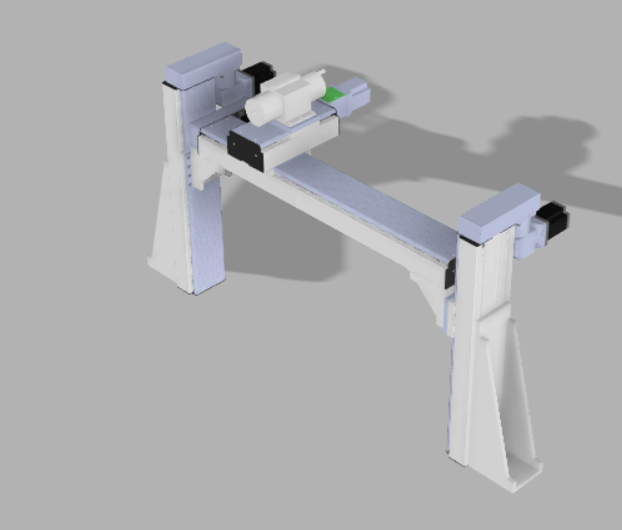
Small Upright CNC
)U~{6U5UYWIDE.png)
This product adopts vertical
design, which breaks the traditional CNC structure. First, it can better observe the state of the processed object during processing. Second, it is more conducive to processing, which is to clean up the waste.
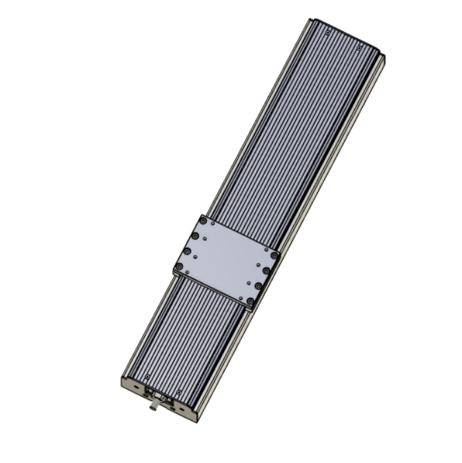
Building XYZ Axis
Y1D0$G8`9E_%VY54.png)
The XZ axis can be obtained
by sketching the feature and modifying the components needed by the feature to create the axis.
Building XYZ Axis
Because of the upright
design, the Y-axis is different in size from the XZ axis and needs to be recreated in the same way as the XZ axis.
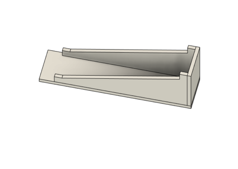
Build Reinforcement
L0ZGHL2.png)
Due to the vertical design,
it is necessary to ensure the stability of the whole machine tool, create features through sketches and modify the construction rib plate to support the machine tool.
Build Reinforcement
![C{}[]`P@}(D3XJD)5N@80}O.png](/proxy/?url=https://content.instructables.com/F6K/EBU8/K28Z77TZ/F6KEBU8K28Z77TZ.png&filename=C{}[]`P@}(D3XJD)5N@80}O.png)
Used to support the
connection between the fixed column axis and the horizontal axis
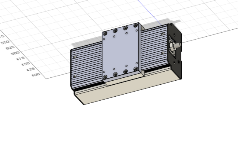
Build Reinforcement
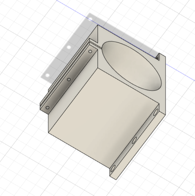F7L6X}A_4H[8X5{SH.png)
In order to ensure the
stability of the cutter head and improve the machining accuracy, it is necessary to reinforce the cutter and construct it with sketch and drawing functions.
Building Transmission
![P][MVM_2I2ZO{TMT0SGLK]6.png](/proxy/?url=https://content.instructables.com/FNX/RE8Z/K28Z782P/FNXRE8ZK28Z782P.png&filename=P][MVM_2I2ZO{TMT0SGLK]6.png)
Building Transmission
![OM86@VY429_]]IGJOAO6P_V.png](/proxy/?url=https://content.instructables.com/FV0/0WJA/K28Z782M/FV00WJAK28Z782M.png&filename=OM86@VY429_]]IGJOAO6P_V.png)
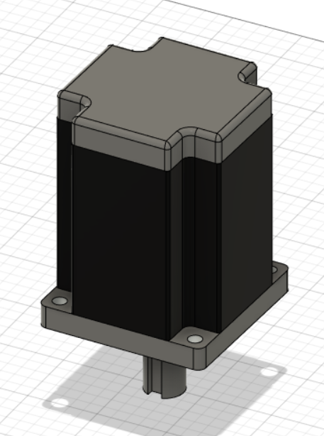
Building Moto
[NUYI3HLER[`4{0CT`JFD.png)
You can select the
appropriate size to compare with the real motor through sketch stretching and feature modification to construct the required motor.
Constructing Tool
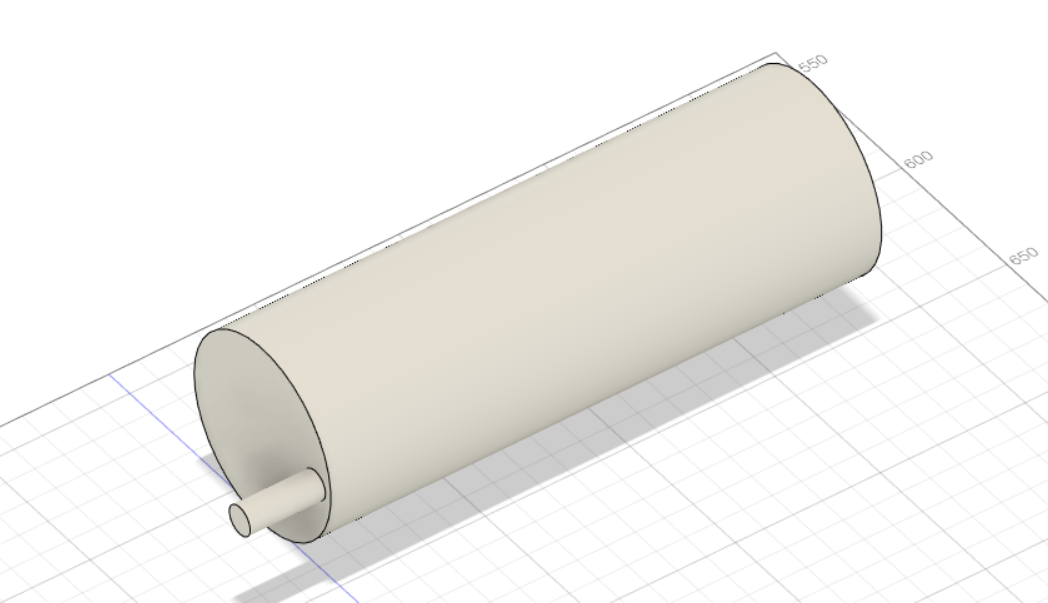
Using sketch and stretch to
construct cylinder structure instead of tool
Assemble All Parts
![]XL)QCYR5[})H{5S1I}VY1I.png](/proxy/?url=https://content.instructables.com/F8Q/TT6A/K28Z77OP/F8QTT6AK28Z77OP.png&filename=]XL)QCYR5[})H{5S1I}VY1I.png)
By using the assembly
connection function, the components constructed in the previous parts are assembled into a whole, and a complete CNC is constructed.
Model Rendering
The material appearance of
each part of the model is changed and further optimized. Finally, the model is rendered through the rendering function to make it more suitable for the real object.