Small Planter
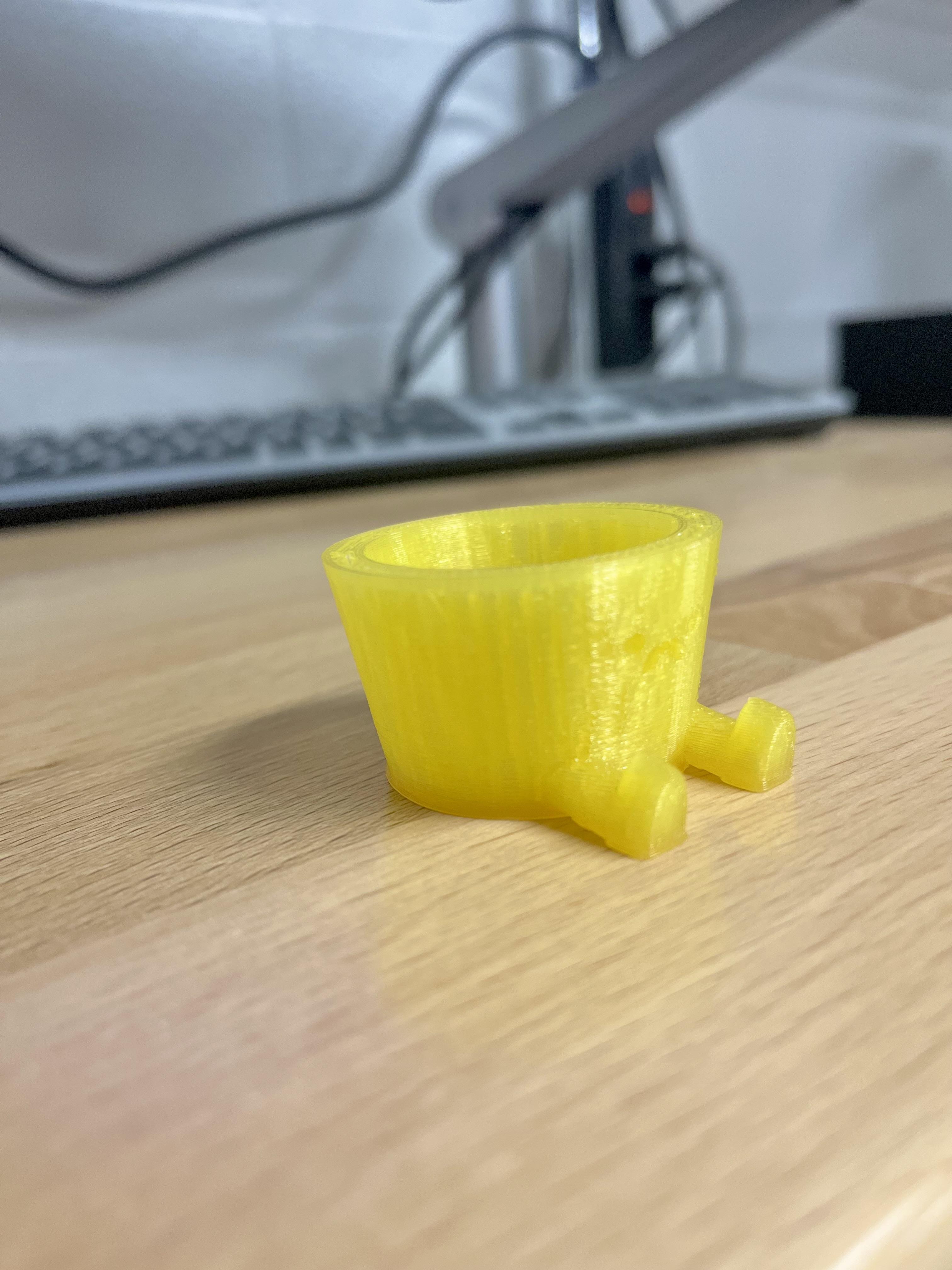
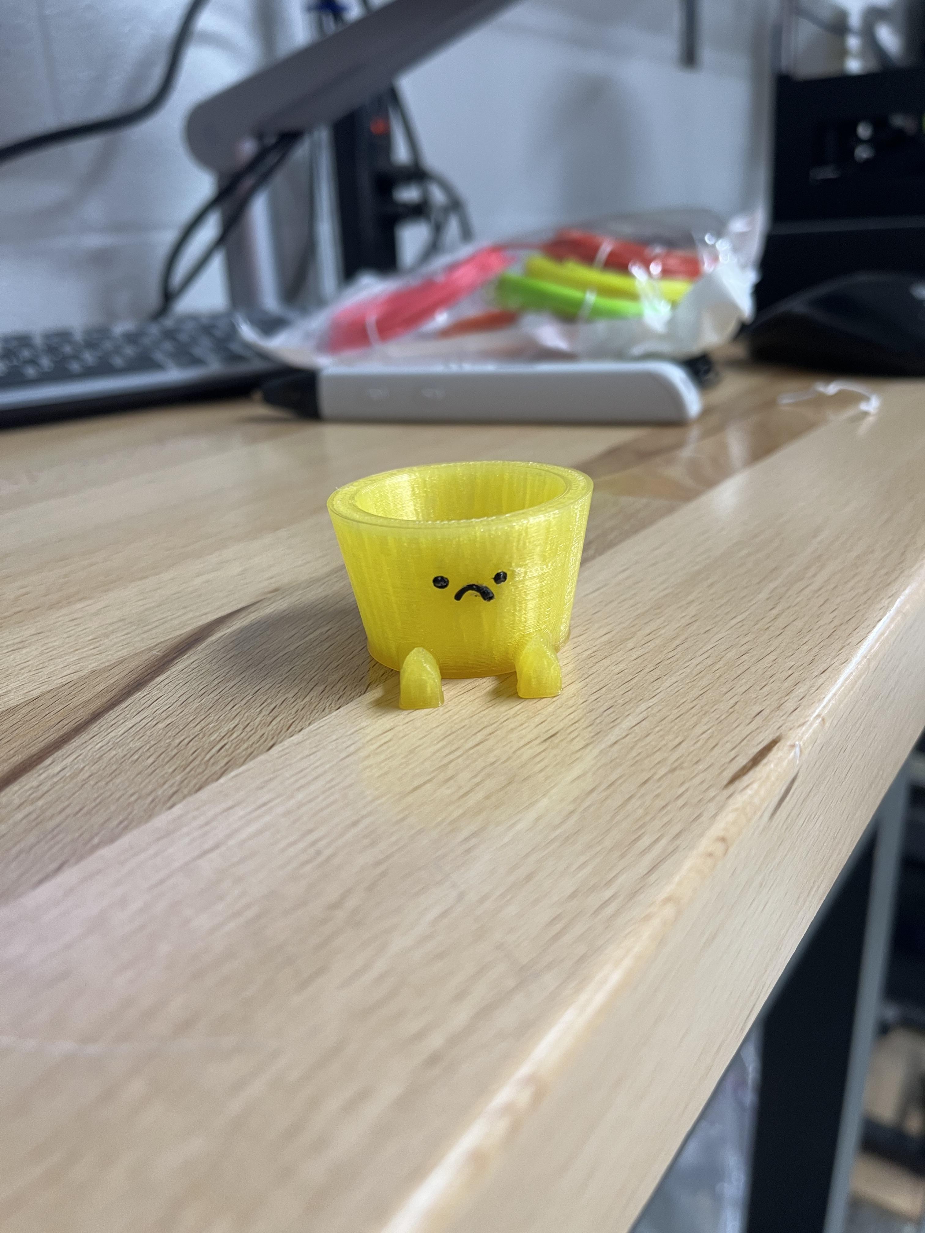
Description: This project will show you how to develop a small planter within SOLIDWORKS. The main point of this is to show off how to create this piece in SOLIDWORKS not show how to use a 3D printer. Although this piece has been scaled down due to time restraints, you can 3D print this item at any scale you want so that it can be a full sized planter functional for any house plant you have!
Target Audience: The target audience for this is high school students (Grades 9-12).
Learning Objective: The goal for this project is to help students further understand how to use SOLIDWORKS and use creativity to create something they can use in everyday life. Students will also learn ways to further their design process.
Standards and Benchmarks:
Standards:
Integration of Knowledge, technologies, and Practices: This is applied from this project because students will be able to take their SOLIDWORKS knowledge from this project and apply it to other fields. Understanding the basic functions of this will allow them to further develop their 3D models in other classes, work places, internships, etc.
Design in Technology and Engineering Education: This helps students to further their understanding about design and help them better understand the process that can go into it. Students are able to look at ideas like this on Instructables and further their design process and come up with new creative ideas.
Practices:
Creativity: This project will allow students to think outside of the box when designing items. They can elements to this project or change things around in order to create a creative planter of their own.
Making and Doing: This process allows students to make their 3D model and then accomplish "doing" by 3D printing their final design. Allowing them to have both aspects furthers multiple skills.
Contexts:
Material Conversion and Processing: This project walks you through how to create a physical product. You can use different filaments when creating your 3D printed planter to suit your needs. Using the 3D printer also allows you to make multiple at a time and speed up the production time.
Supplies
-Computer with SOLIDWORKS Version 2021-2022 (License to this can be expensive but normally free if school provides it)
-3D Printer (These can cost thousands of dollars but normally the school will provide one or you can find a local store that 3D prints (like some UPS stores) for $20-$500 depending on how complex the project is.)
-Filament ($20-$30 per role)
-3D Pen (Optional) (Around $50-$60 on amazon but can find cheaper else where.)
Note: You can use a different year of SOLIDWORKS but some steps may not be located or look the same way as described in the photos.
Base Shape
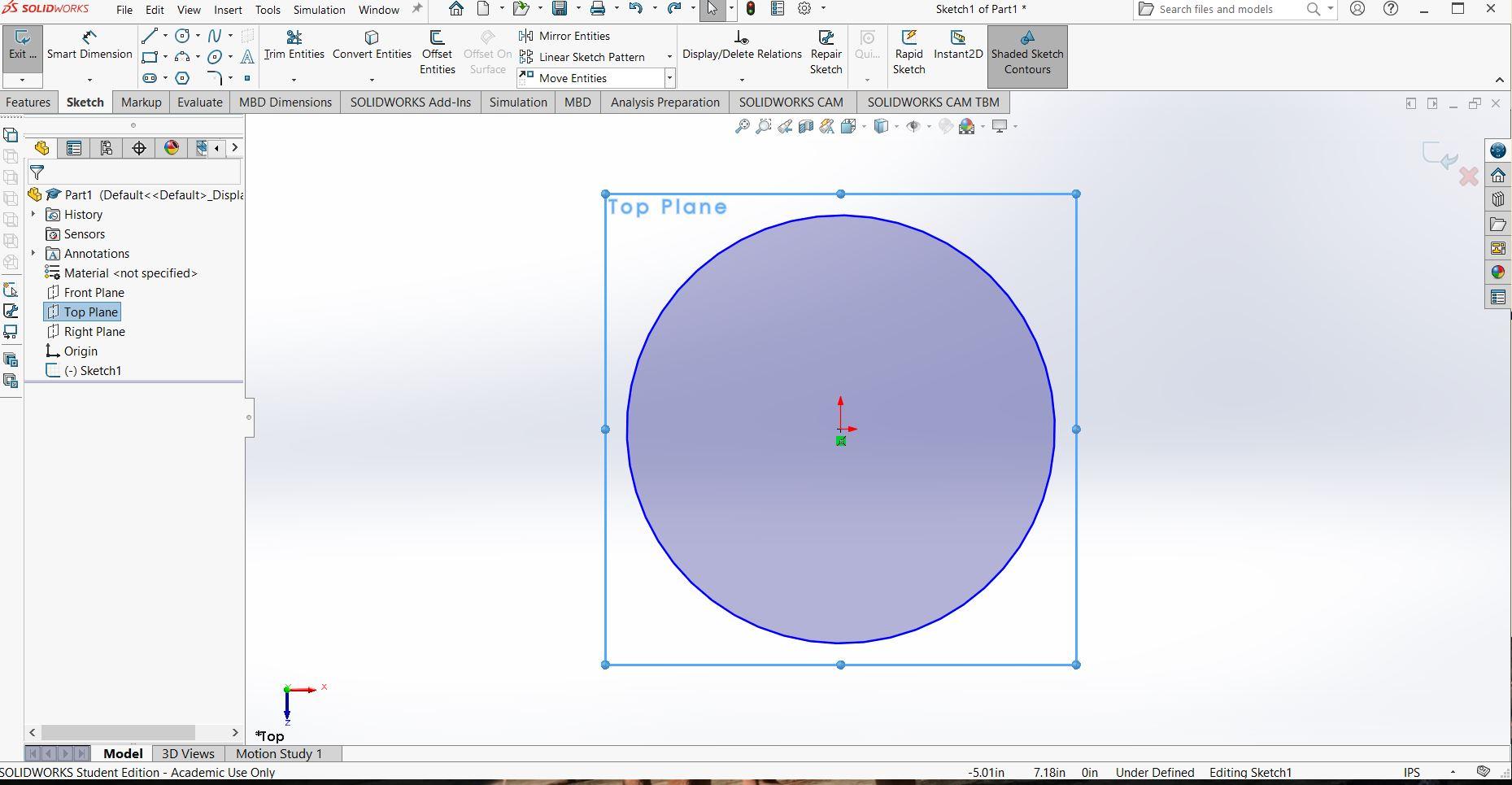
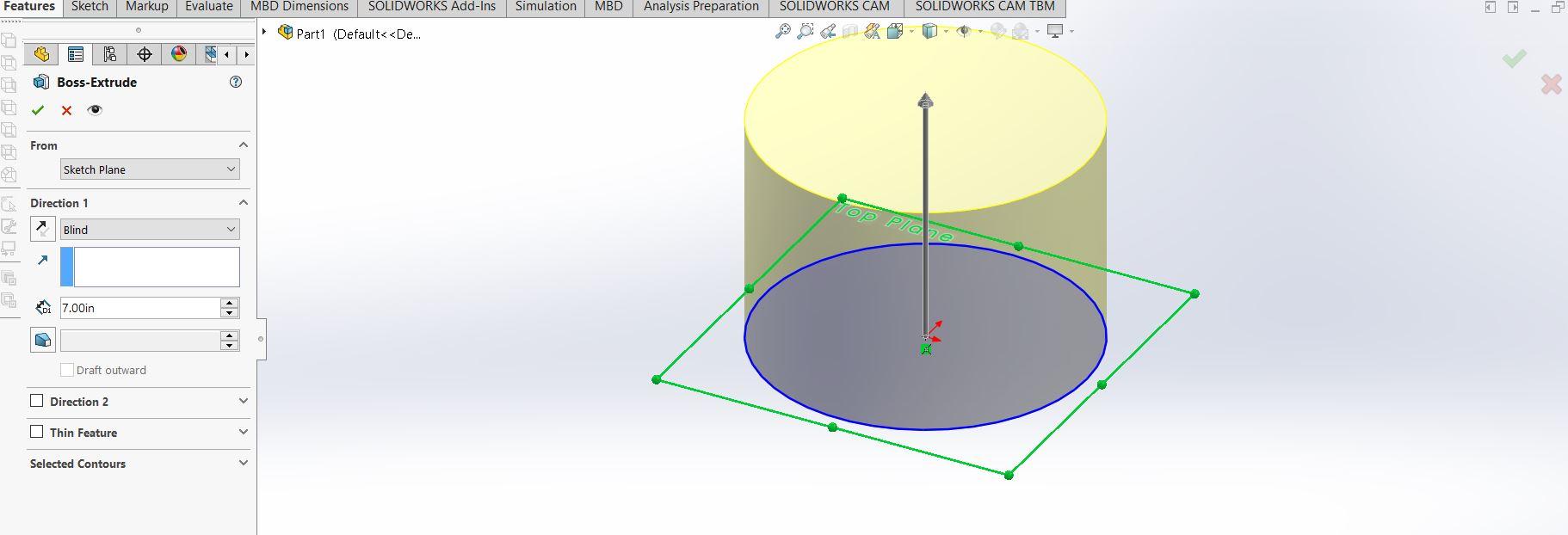
First you need to open up solid works. Once the application is open start a sketch on the top plane. Create a circle with the diameter of 10 inches. Then boss-extrude the circle by 7 inches.
(Click on the photos to see all of the side bars in each step)
(Also make sure to save after each step)
Draft the Base Shape
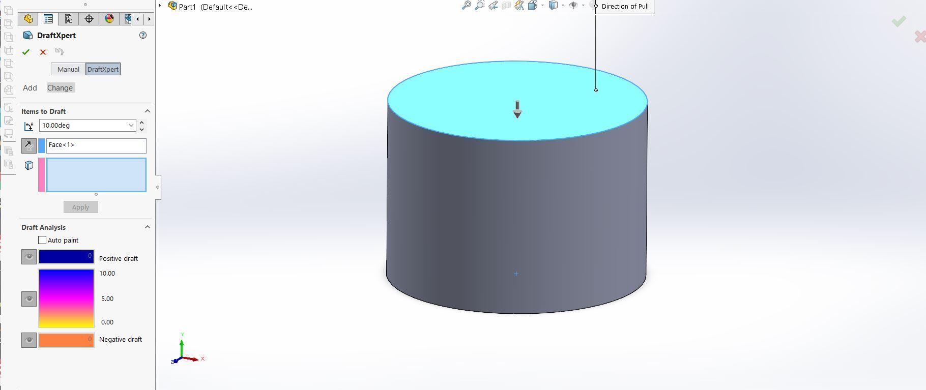
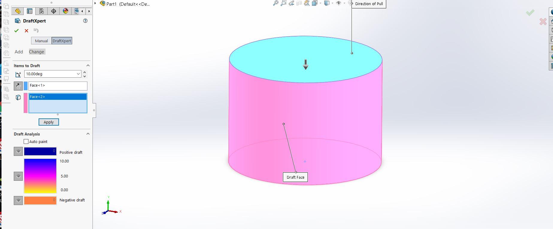
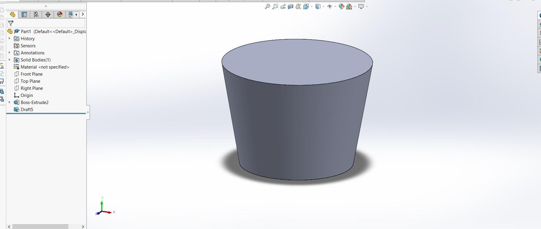
Next click on the draft button in the feature tab. Once on that page select the two faces as shown above, and change the angle to 10 degrees. Press the green check when done. It should look like the third picture above.
Shell the Base Shape
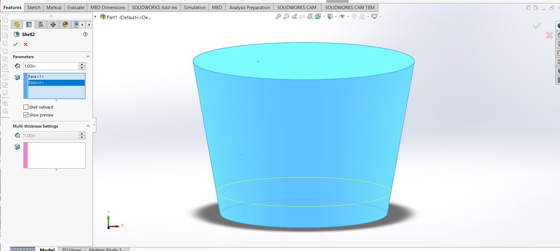
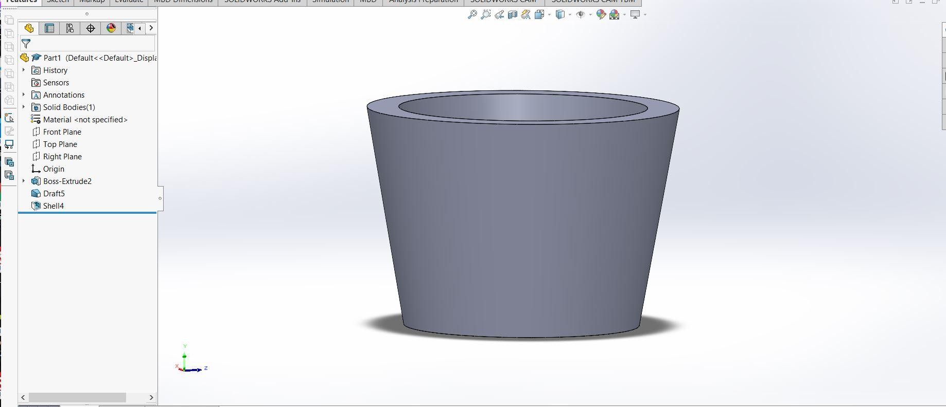
Next you are going to select the shell feature located right below the draft button on the features tab. After selecting the shell feature you are then going to select the top and side faces of the base shape (it should highlight blue). Change the dimension to 1 inch. Once completed press the green check and it should look like the second image.
Create the Drainage Hole
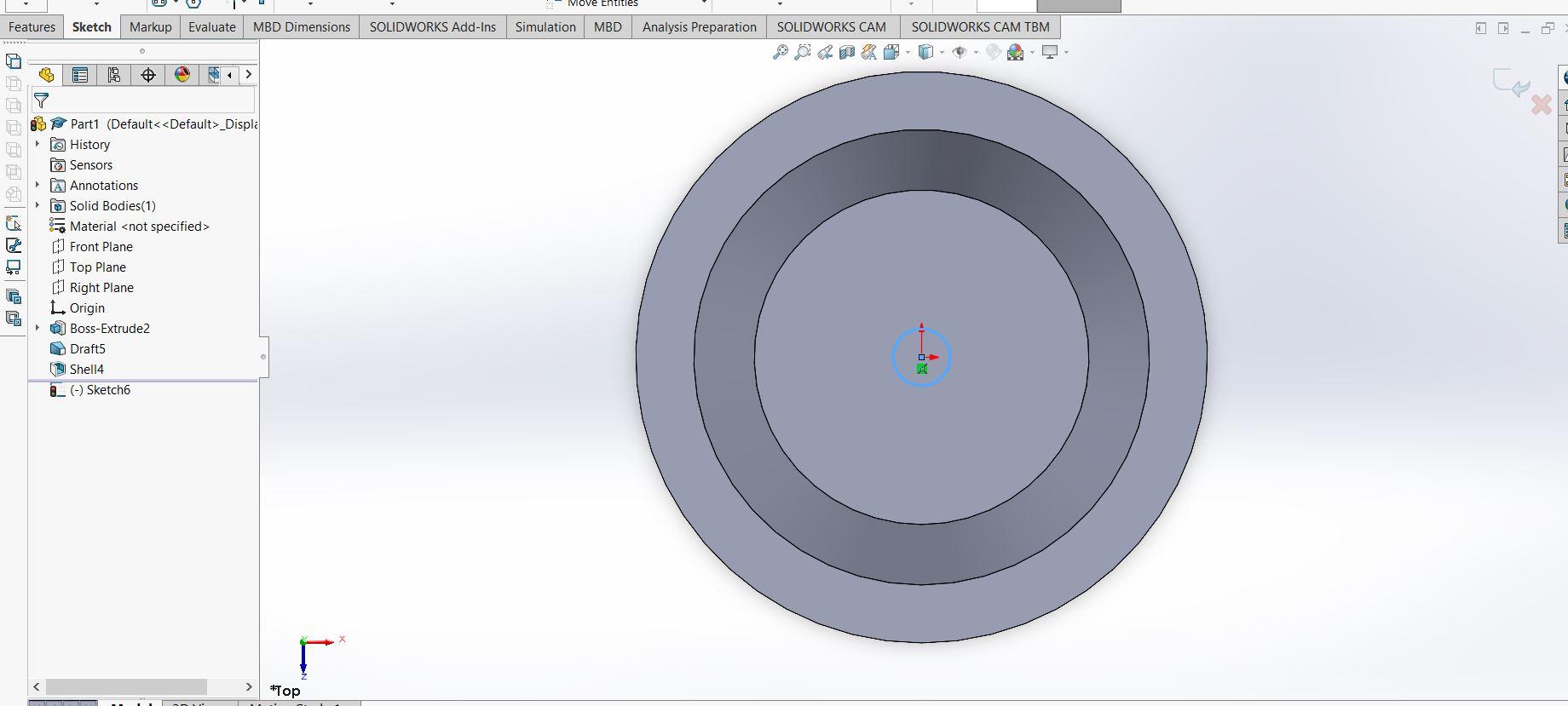
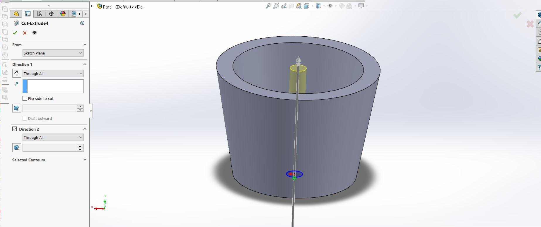
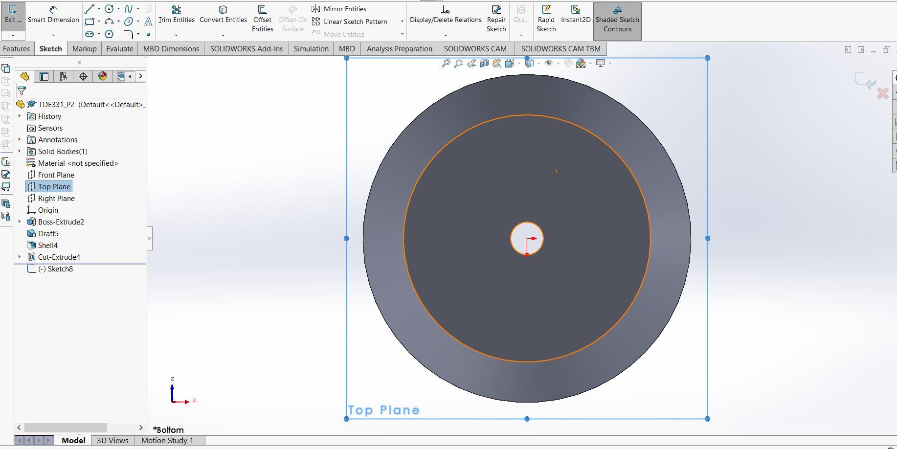
You are then going to create another sketch on the top plane. You will create a circle that has a 1 inch diameter. Once that is created you will go to the feature tab and extrude cut. You will change the "Direction 1" to "Through all". Once you do that hit the green check. It should look like the third photo provided.
Making a New Plane
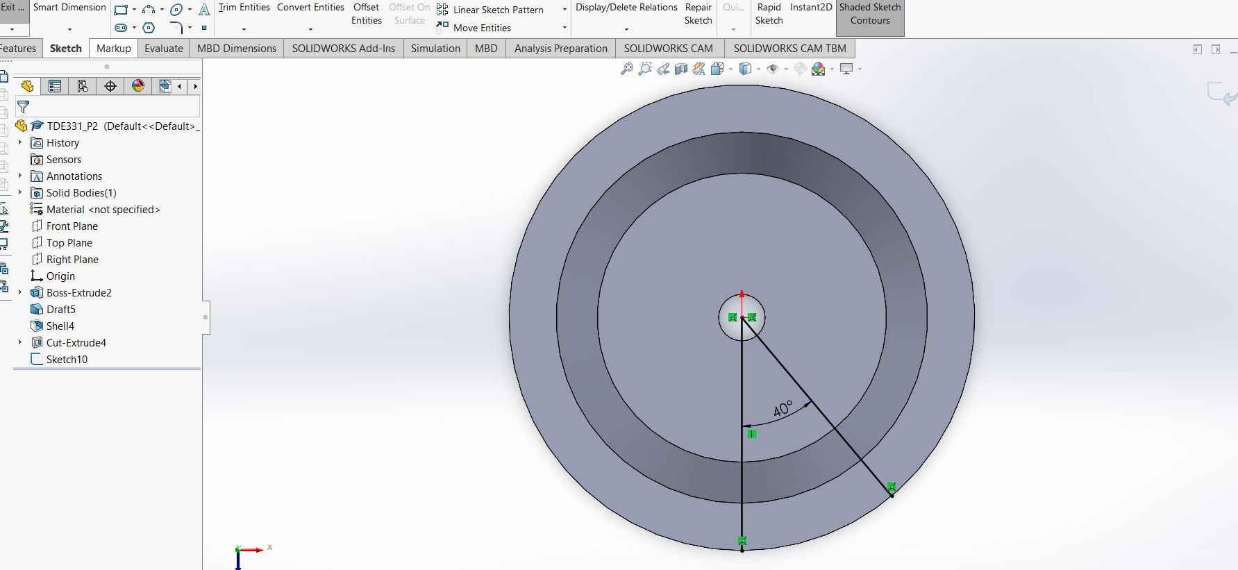
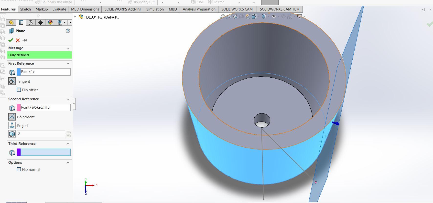
You will need to create a new plane in order to add the face and leg features. First you need to create reference points. Start a new sketch on the top plane again. Create a straight line going from the middle to the bottom edge and another from the middle to an outer edge. Add a dimension between these two lines that is 40 degrees (shown in image 1). Once that is complete exit the sketch. Now to create the reference plane. To do this go to the features tab > hover over references > click plane. Once here select the side face of the base shape as first reference (it should highlight blue) and select the end point of the line sketch prior (it should highlight pink, view photo 2). Once completed you should be able to preview the plane. Select the green check mark.
Here is a link to a video that further shows how to create this new plane! https://www.youtube.com/watch?v=wGBD5D8i0jg
Creating the "legs"
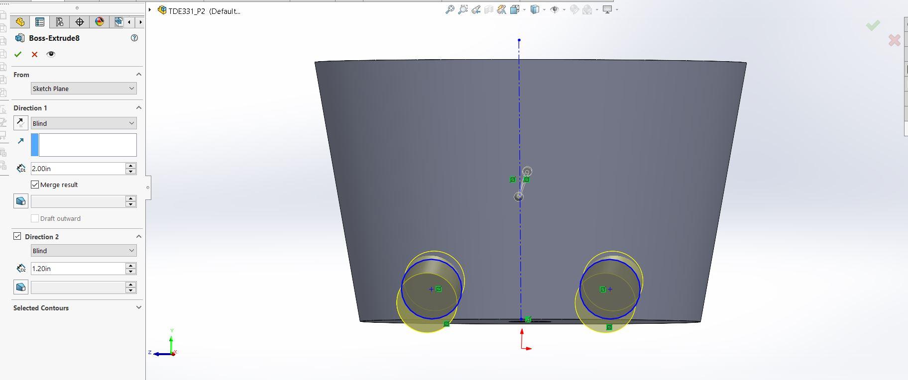
Start a new sketch on the plane we just created. Sketch a construction line straight down the middle of the base shape. Create a circle that 1.4 inches in diameter and 2 inches away from the middle construction line. Then click the mirror entities button on the sketch tab, and mirror the circle across the construction line. It should create two identical circles on the plane (similar to the first picture). You will then boss extrude these circles in the first direction 2 inches and in the second direction 1.2 inches. Press the green check mark.
Legs Continued (feet)
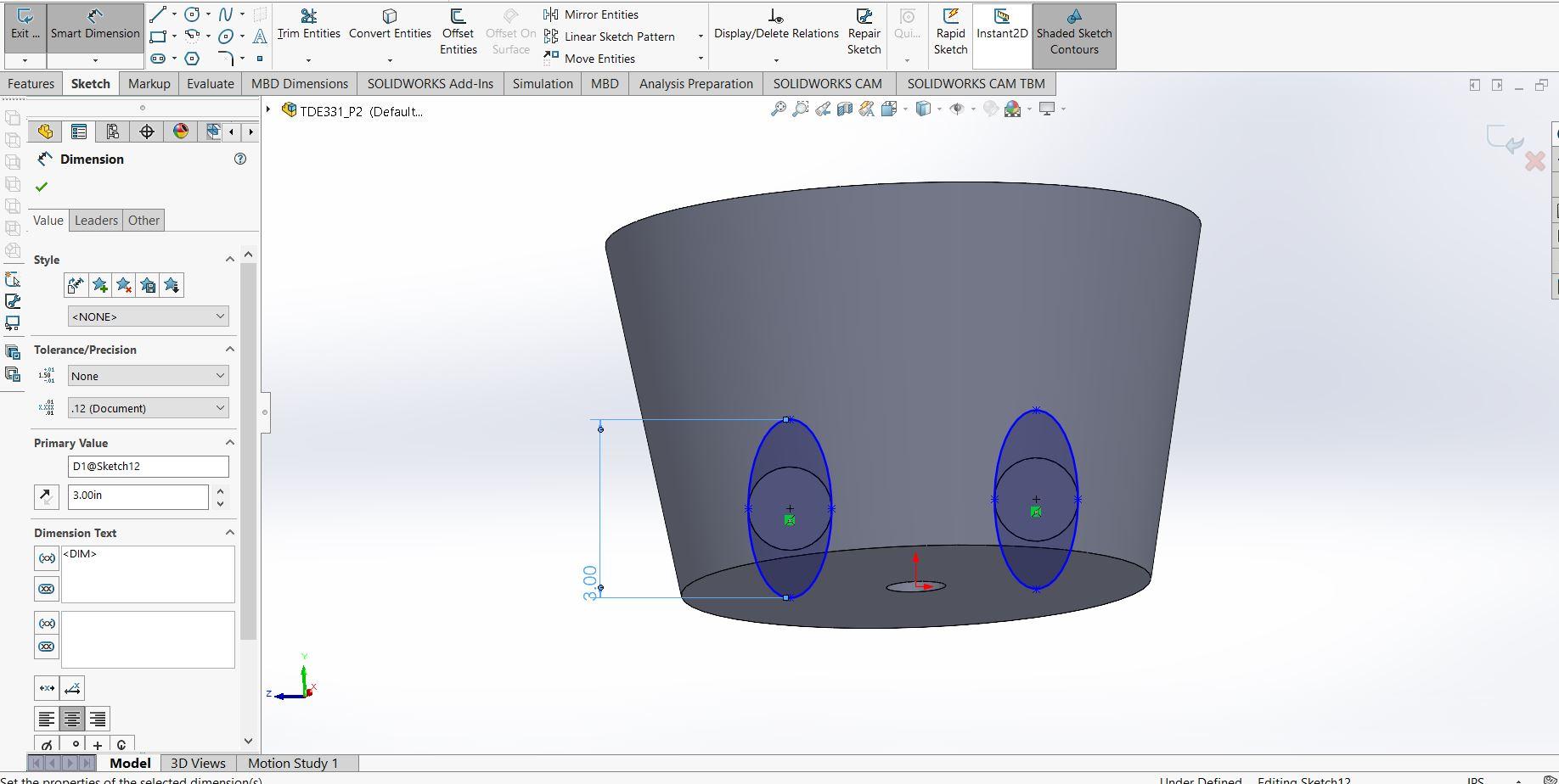
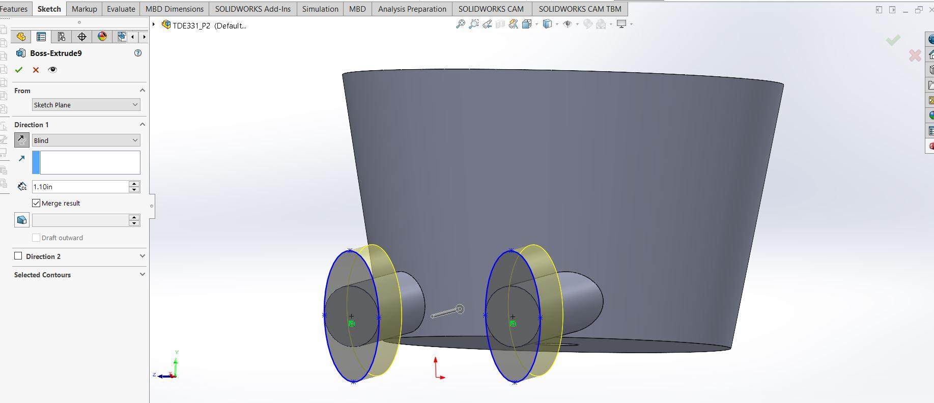
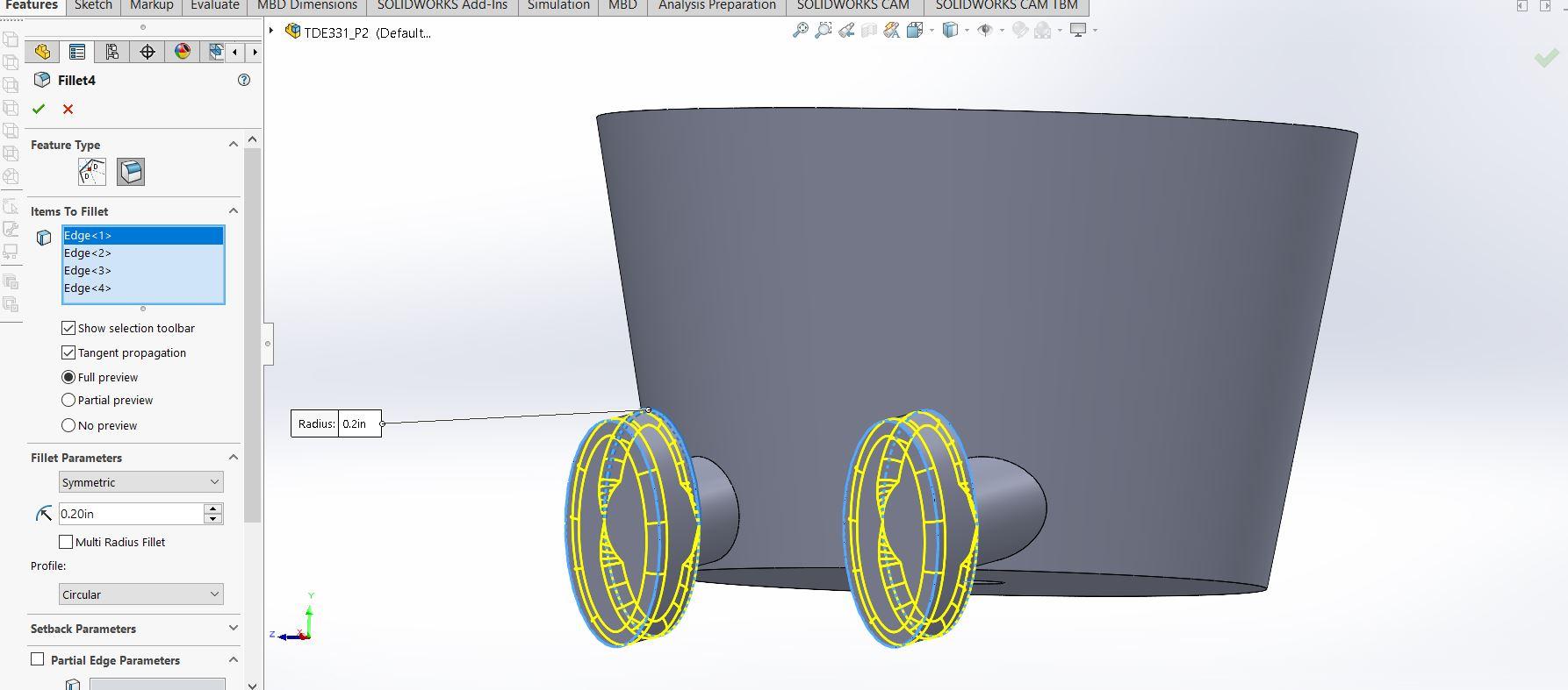
To add the feet you will create a sketch on the ends of the extruded legs. Sketch an oval that is as wide as the previous circles and 3 inches tall (see picture 2). You will then boss extrude these towards the base shape 1.2 inches. Click the green check mark. Next click the fillet button on the features page. You will want to select the edges of the ovals you just extruded. You will want to make the radius of these .2 inches. You should see the preview in all yellow (seen in the 4th picture). Then click the green check.
Flatten the Bottom of the Figure
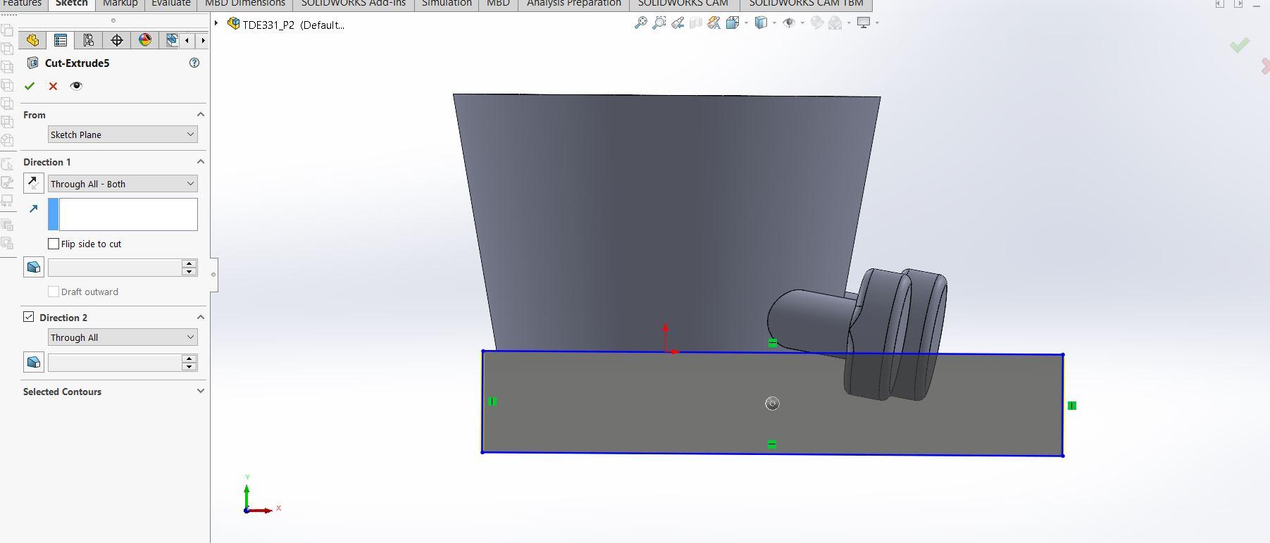
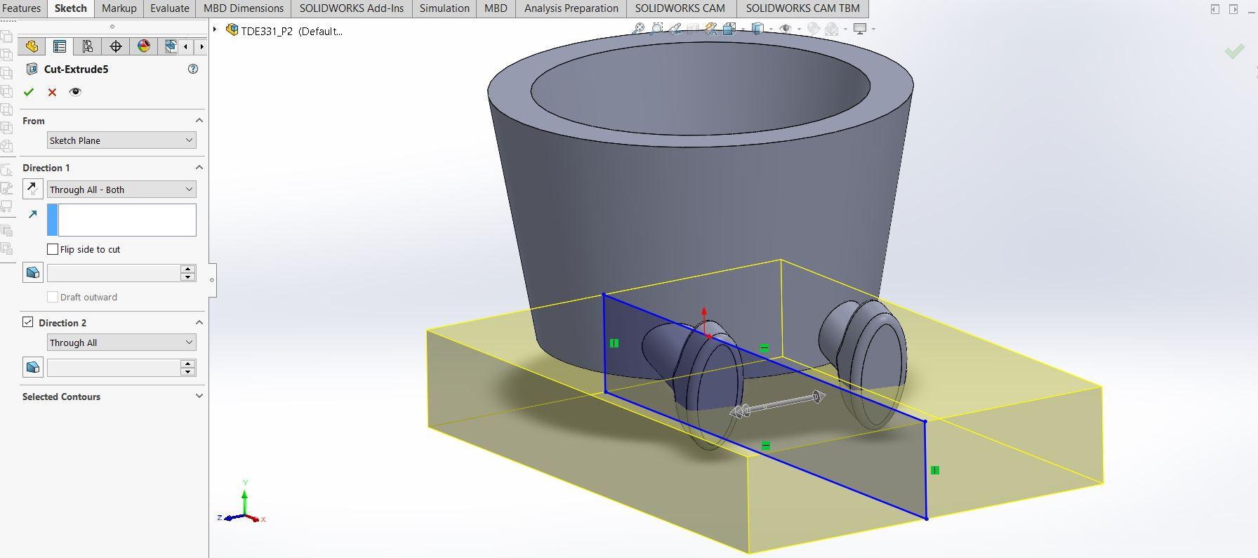
In order to make this easier to 3D print flattening the bottom of the figure will lessen the needs for any supports (which can be aggravating). To do this start a sketch on the front plane. Create a rectangle that starts at the bottom of the base shape and covers the length of the whole figure (seen in image 1). Next you will extrude cut and select the direction "Through All - Both" (it should look like the second image). Select the green check mark and the bottom of the figure should now be flat.
Create the Face
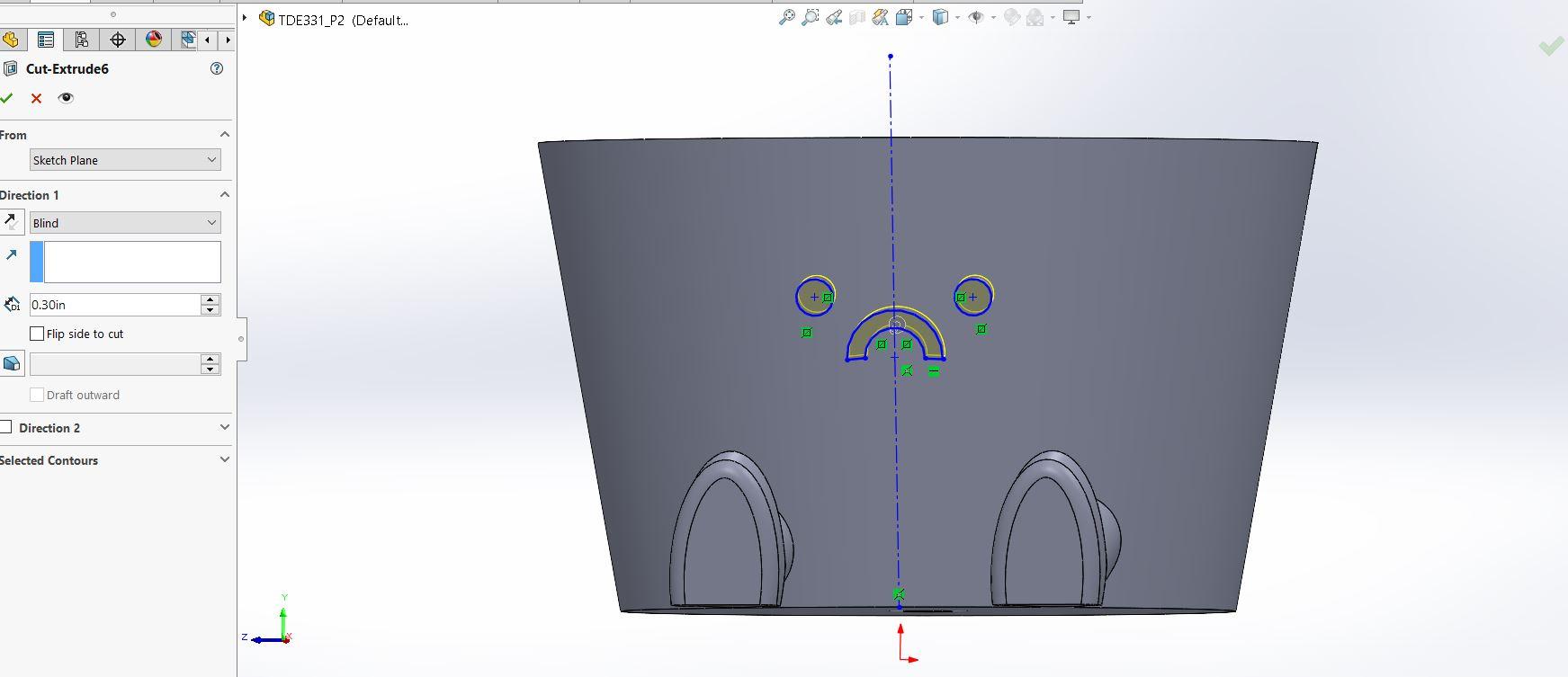
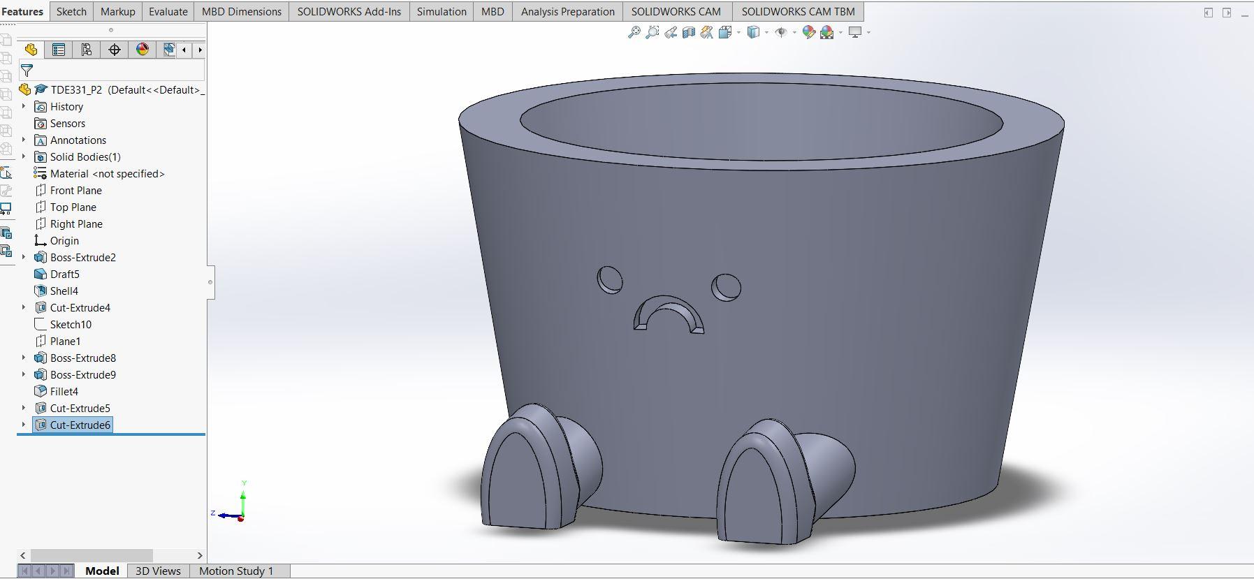
To create the face of your planter start a sketch on the plane that we created. You can create any face that you want, but I will describe how I made mine. I created a construction line straight down the middle of my base shape. I then created a .5 inch diameter circle 1 inch away from the middle construction line. I then mirrored this circle across the center construction line to create the two eyes. I then used the line and center point arch tools to create the frown. These measurements aren't too precise, I just created the shape to look the way I wanted. Once you create these shapes you can extrude cut them .3 inches into the base shape. Click the green check mark, and you are done! It should look like the second image. Save as an STL file in order to 3D print!
3D Printing
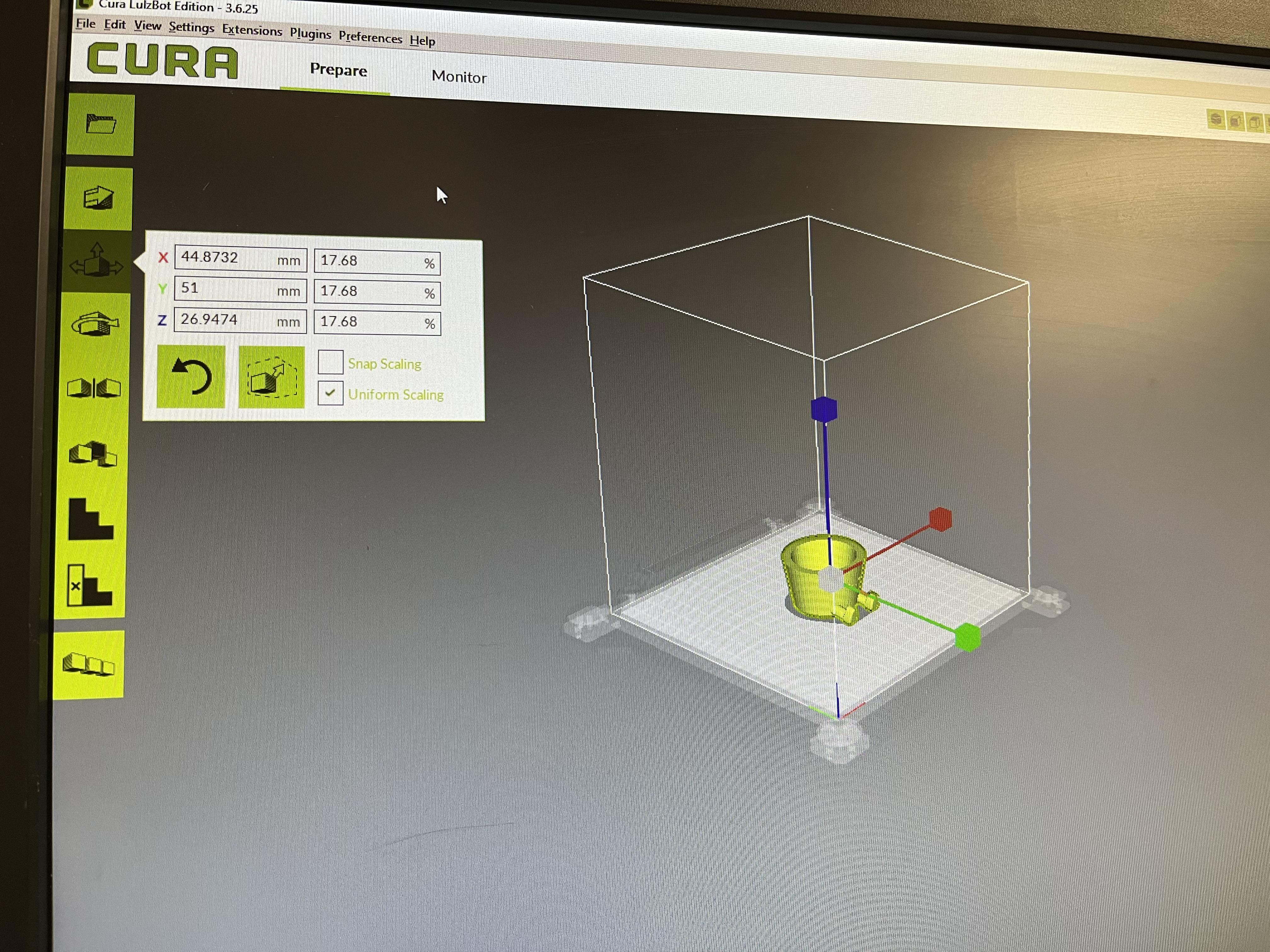
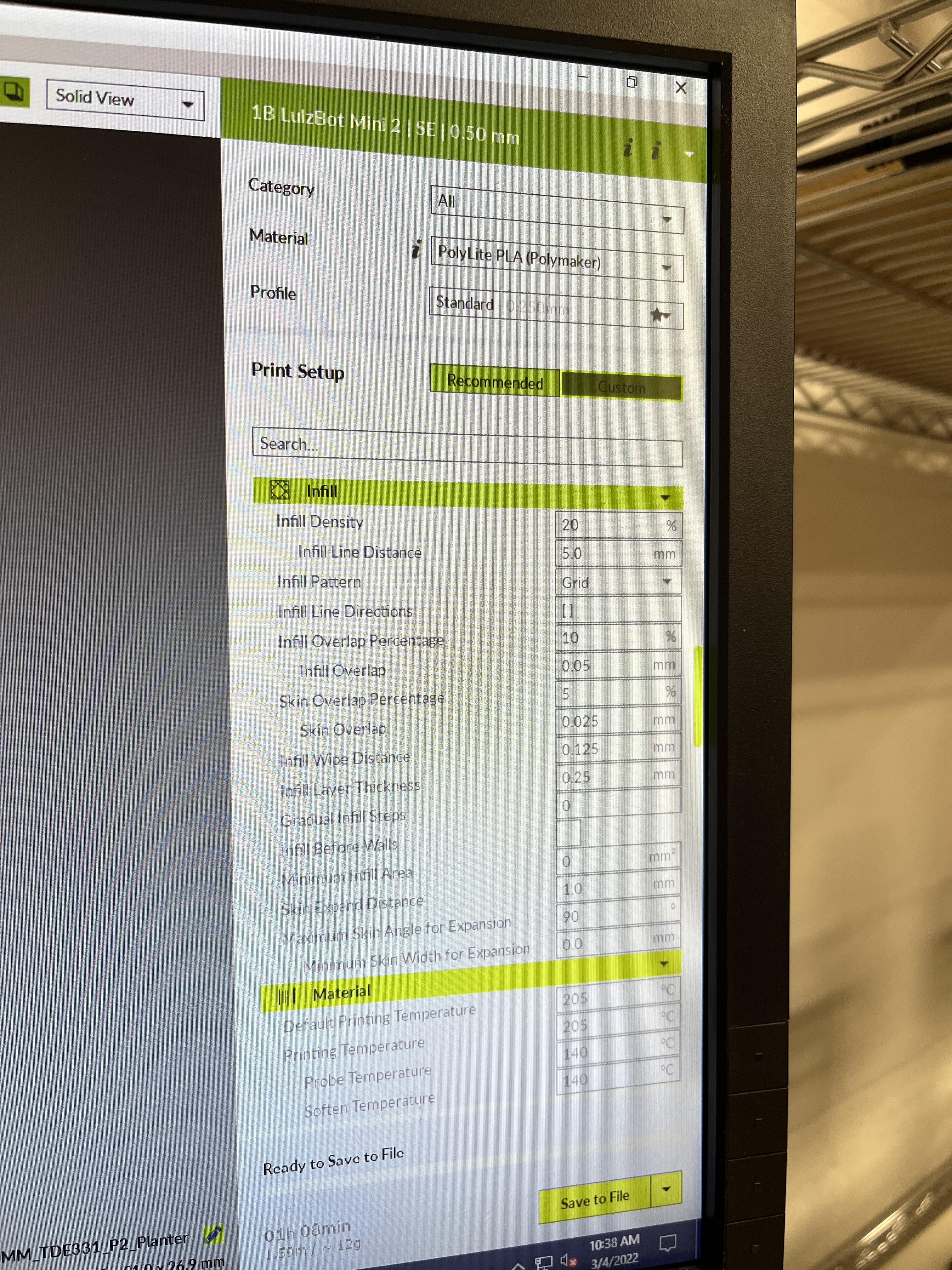
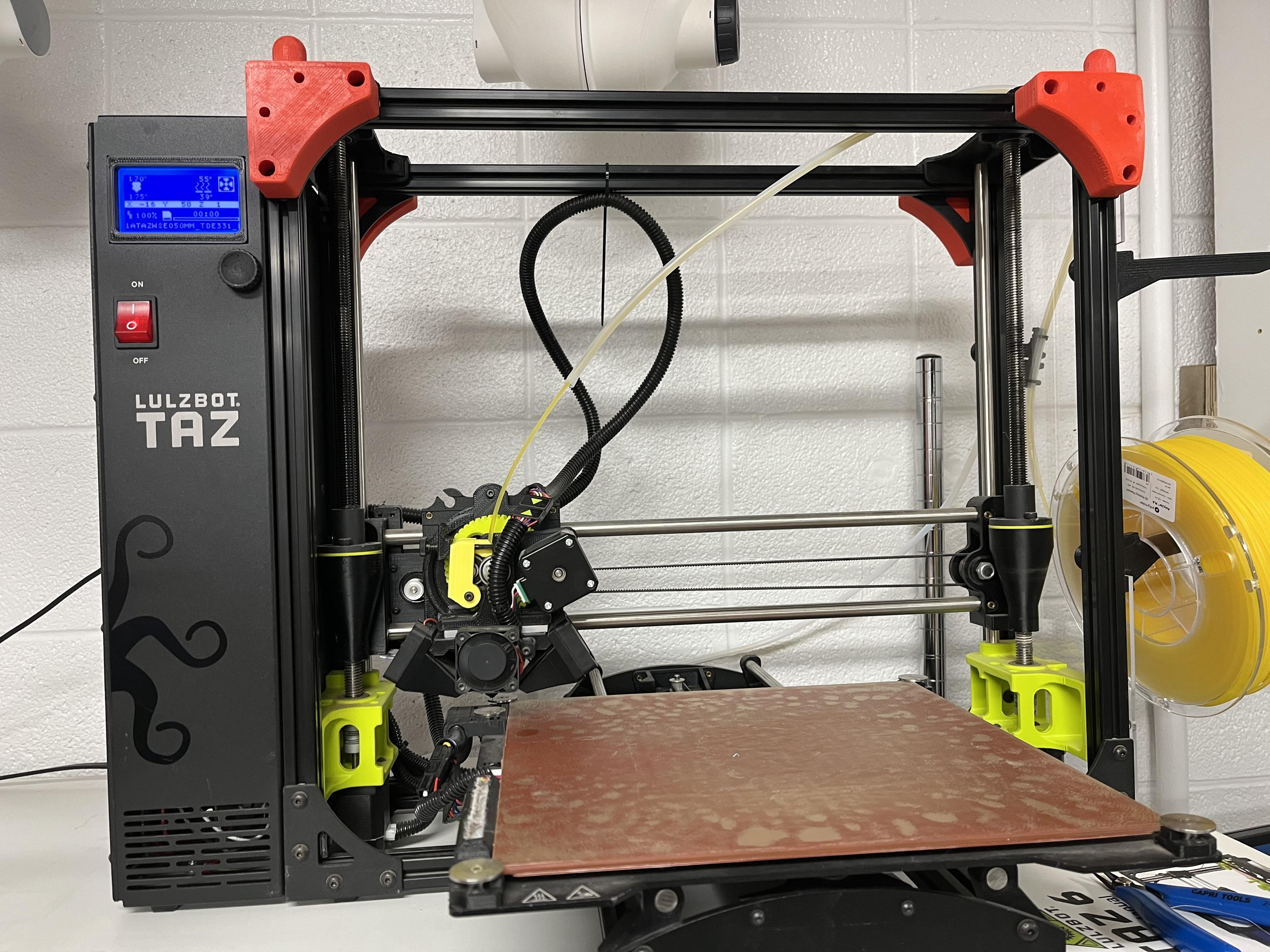
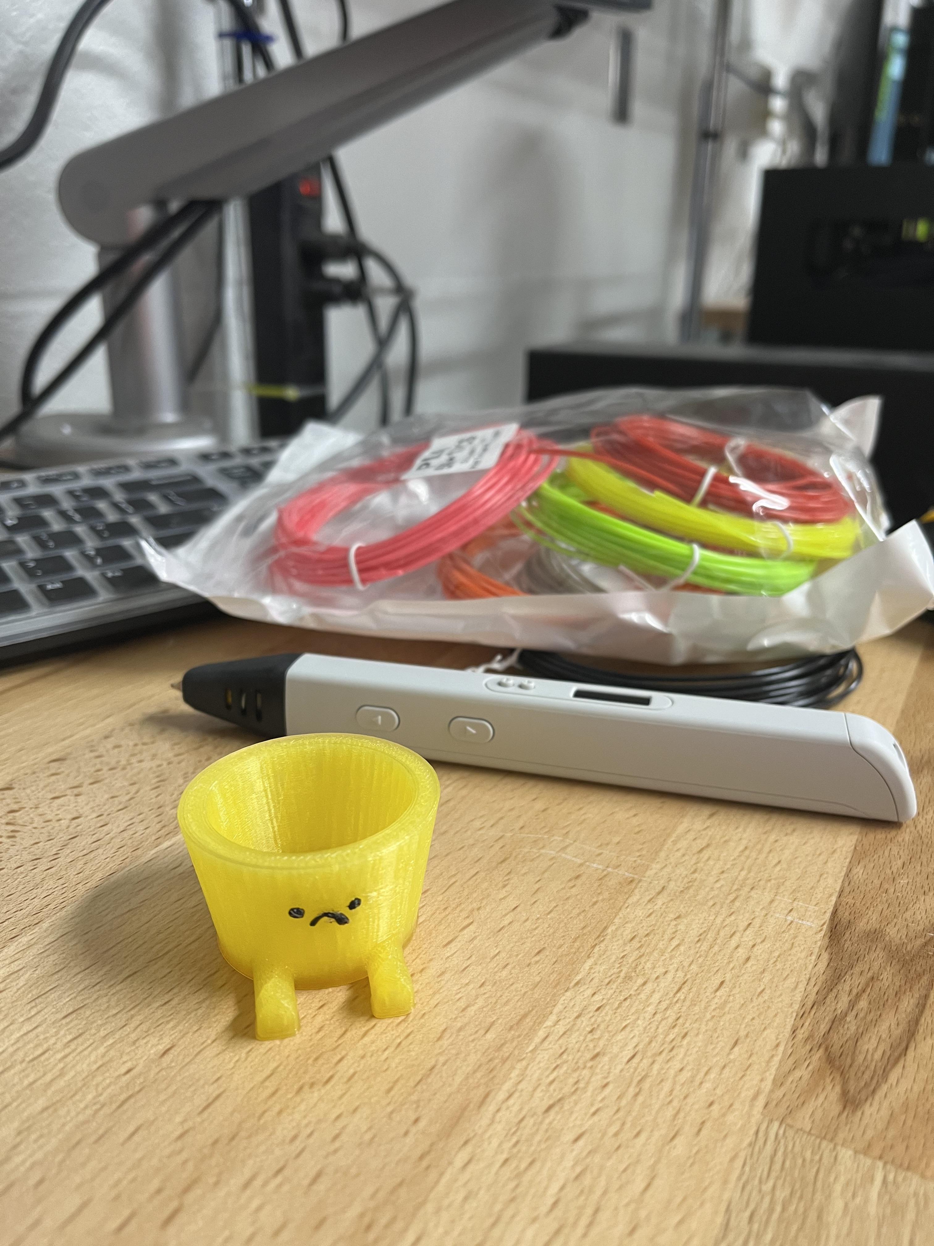
Although this is meant to teach you how to model and not 3D print, I added a few images and steps on how I 3D printed this.
-I first added the STL file into the 3D printing app called CURA.
-I then scaled it down to the size I needed in order to print 3 of them in a few hours. This ended up being only about 2 inches big because of the time restraints I had, but feel free to make it as big as you want! Just know that making one of these full scale may take over 6 hours.
-I then saved the scaled file in the correct format onto a sd card and inserted that into the 3D printer.
-After that I prepped the printer and began the prints.
-Because I used a light color filament and had to print so small it was hard to see the face cut outs on the planter. In order to make these more noticeable I used a 3D pen and filled in those small cut outs. This is completely optional.