Small Magnetic Storage Box/tray
by mojo586 in Workshop > 3D Printing
1429 Views, 13 Favorites, 0 Comments
Small Magnetic Storage Box/tray
.jpg)
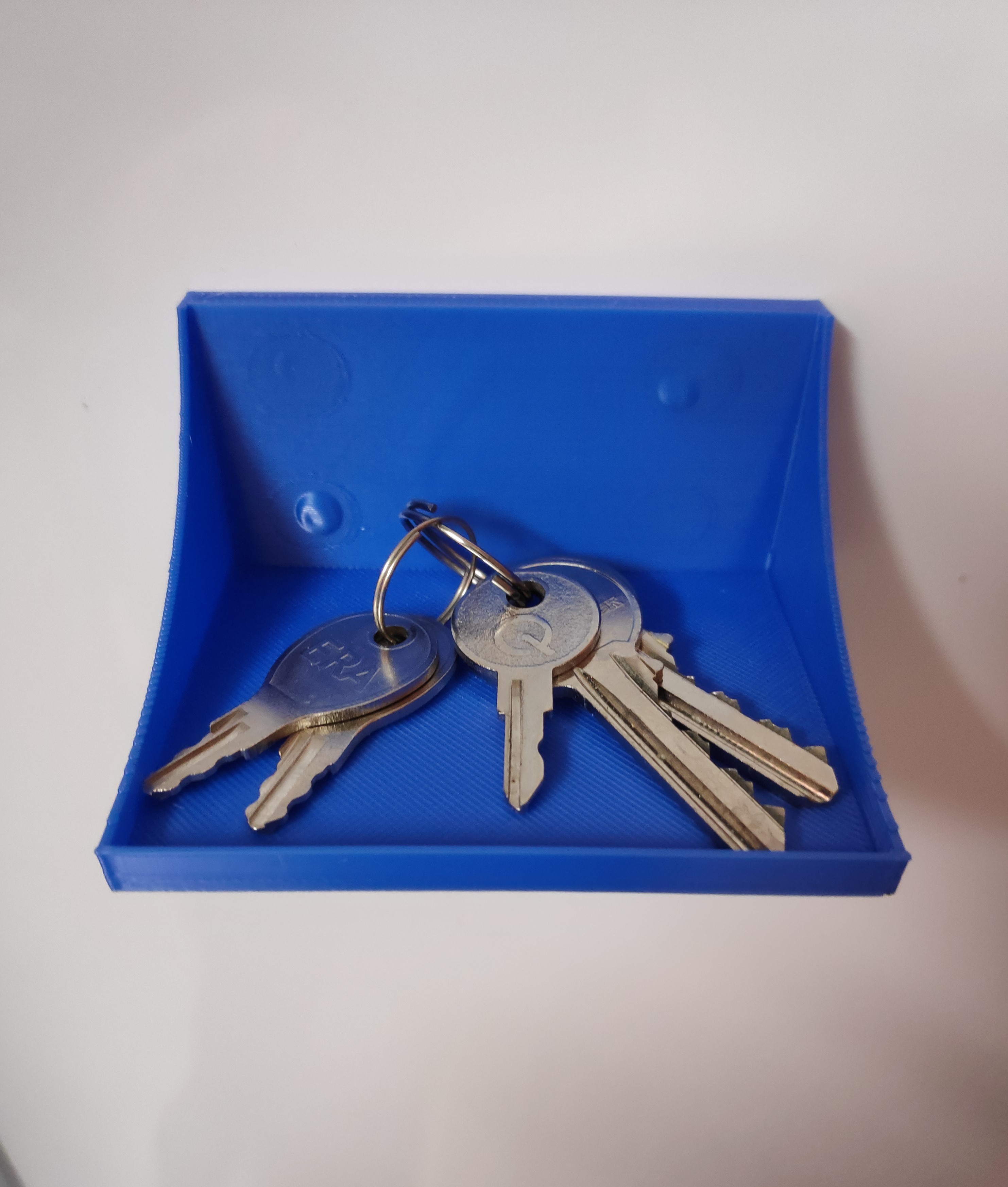
This idea came about because I am always looking to get my stuff organised and living in a small flat in London space is at a premium! In this Instructable I am going to show you how to use Tinkercad to design and then 3D print a small box/shelf, glue some strong magnets to it and use it to store anything you like. Mine is attached to the fridge and used to store keys!
Having failed to get to grasps with 3DS Max at university I have put off going back to it many times due its feature rich interface always looked intimidating to me. That is until I discovered Tinkercad which I really love! It's simplistic, yet powerful interface has much to offer and you can create many complex designs with it. These designs can then be exported to STL for 3D printing or SVG for laser cutting.
If you are new to Tinkercad head over to www.tinkercad.com and create yourself an account then get started with the inbuilt lessons provided, there are 7 basic lessons in the collection and that is pretty much all you need to use it. Obviously you might already be familiar with Tinkercad or some other design tool in which case skip the lessons as you see fit and head straight to the steps below. A set of 5 lessons that provide additional step-by-step instructions for Tinkercad can be found here.
Supplies
In addition to a computer with internet access to accessing Tinkercad you will also need a 3D printer to print the model. If you do not have a 3D printer ask a friend or check out your local Makerspace. Other materials needed are:
- Hot glue gun & glue
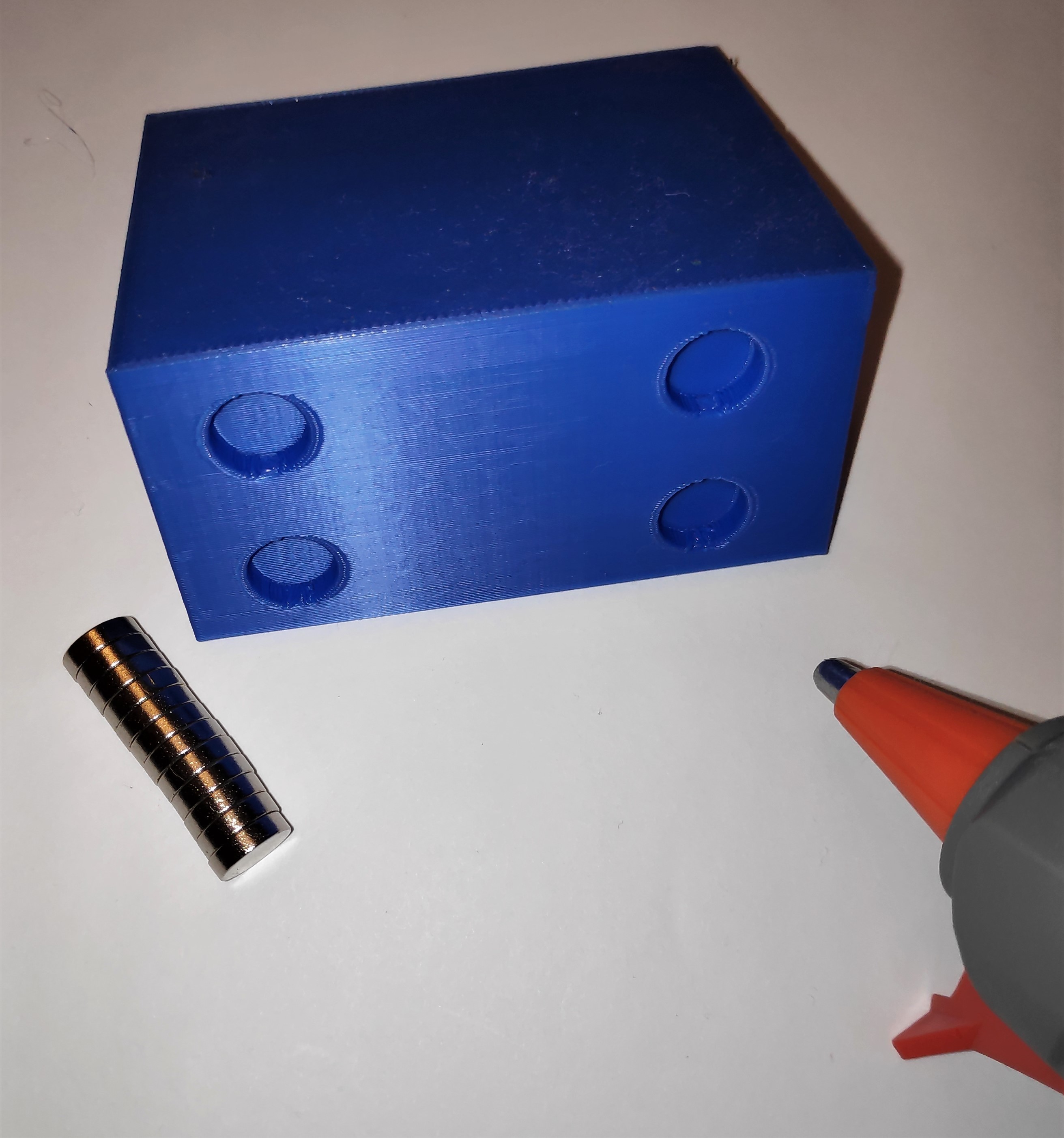
- 4 x Neodymium magnets (10 x 3mm)
Create a New Design

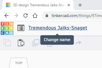
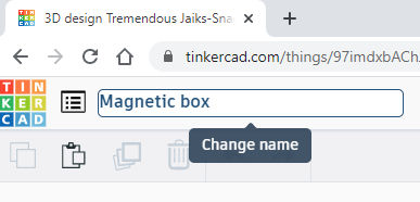
After you have logged in to Tinkercad and completed the lessons if required you will need to start with a new design. On the main page of Tinkercad click Create new design as shown in the image. This will create a new design with a random name, it is best if you give your new design a sensible name - 'Magnetic box' in this case as shown in the image.
Create a Box
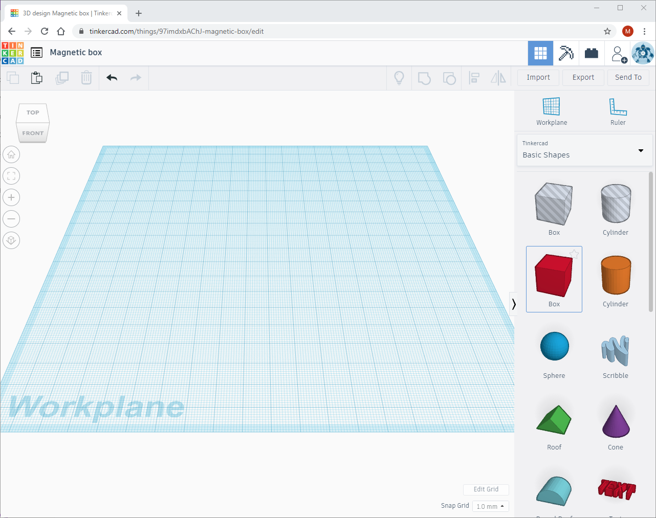
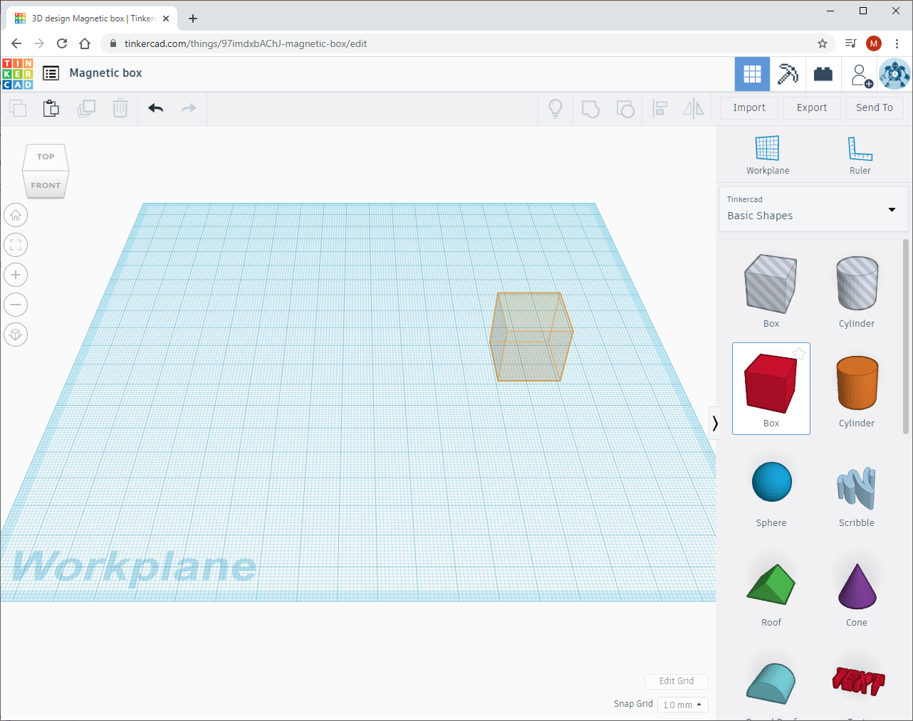
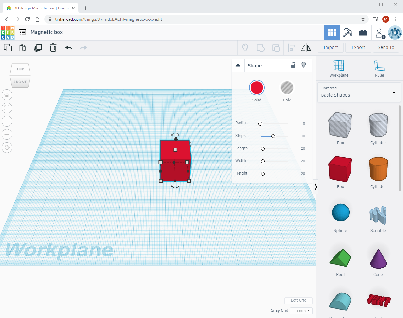
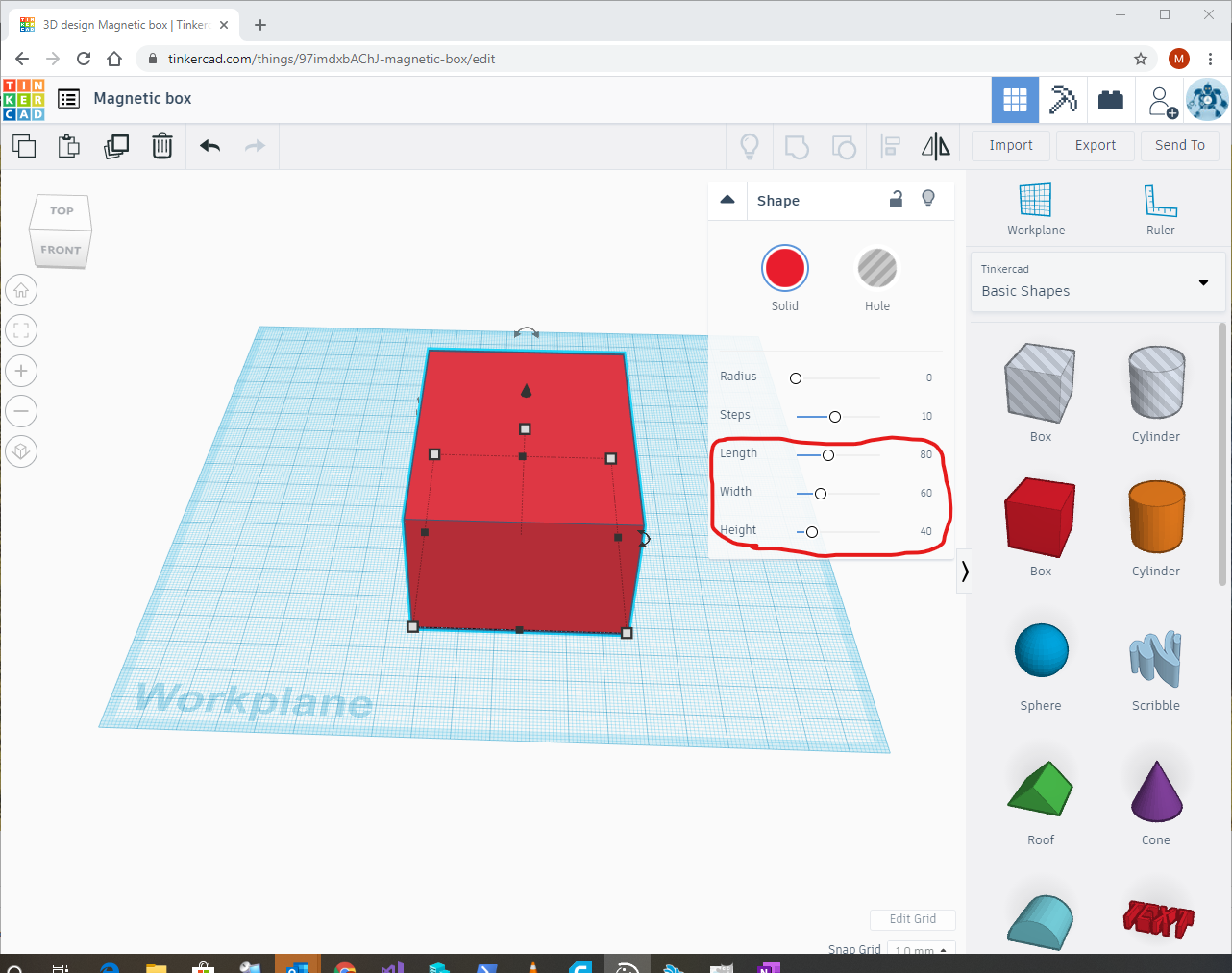
For my box I decided to use the following dimensions (width = 60mm, height = 40mm, length = 80mm). As you can see I am using millimetres for units rather than centimetres to keep things precise and also because this is the default unit in Tinkercad. To start off your design drag and drop a Box into the Workplane from the Shapes menu. Use the Shape properties to adjust the width, height and length as highlighted in the image; use the above values or your own dimensions if you are creating something specific for yourself.
Duplicate It
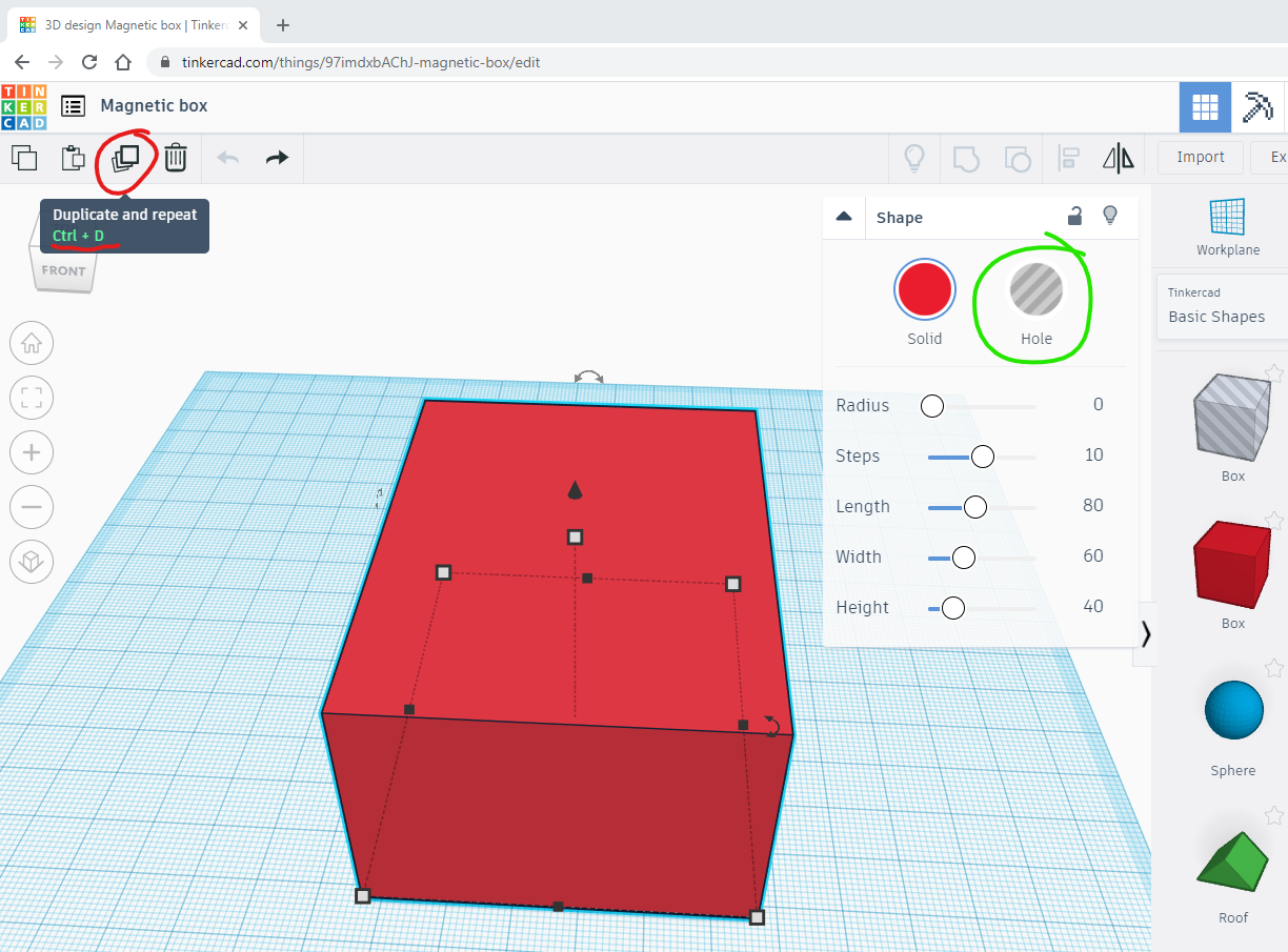
In this step we are going to duplicate the box, to make a hole in the box. Alternatively you can drag the transparent shape in the Workplane and change its dimensions as required (given shortly).
With the box you placed from Step 2 selected click the Duplicate button (see image - highlighted in red) or press Ctrl + D. This will create a duplicate of the box which will be selected. From the shape properties window Click the Hole option (as shown in the image - top-right - highlighted in green).
Modify the Duplicate
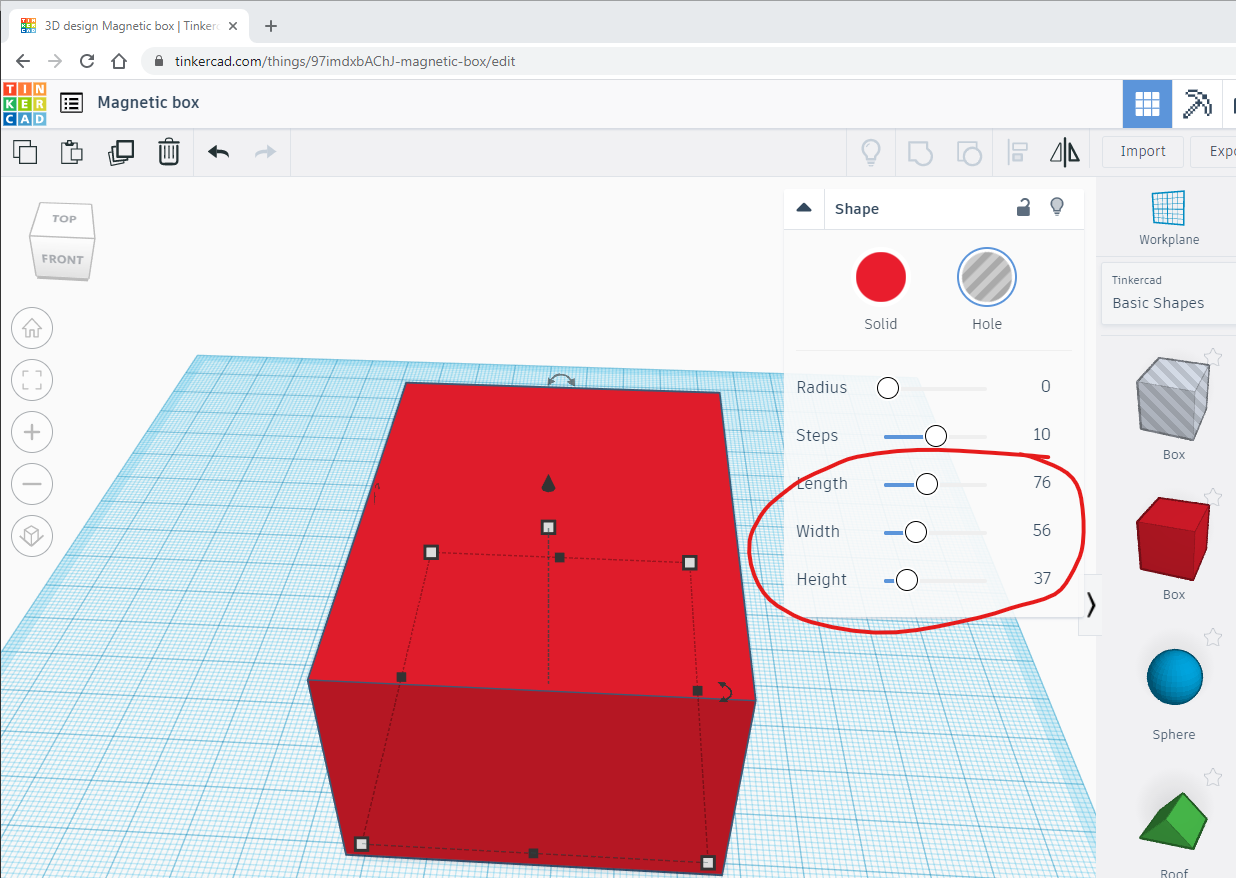
With the duplicate hole box still selected change the dimensions as follows: (width = 56mm, height = 37mm, length = 76mm). What we are doing here is creating a box that we can use to 'carve' out from the box in step one. The reason why we make it smaller is to allow for borders, otherwise the boxes would negate each other and we would end up with nothing once we group them in Step 6 below.
What this also means that we are allowing for borders of 2mm and a bottom of 3mm, which is what I prefer. You can change these settings if you would like i.e. to make the border smaller (1mm change the width and length to 58mm and 78mm respectively) and height to 38mm to give the box a bottom of 2mm. This might be better if you are creating a smaller box or alternatively if you are making a bigger box you might want to increase the border to 3mm.
Align the Boxes Correctly
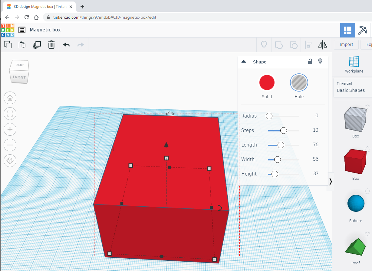
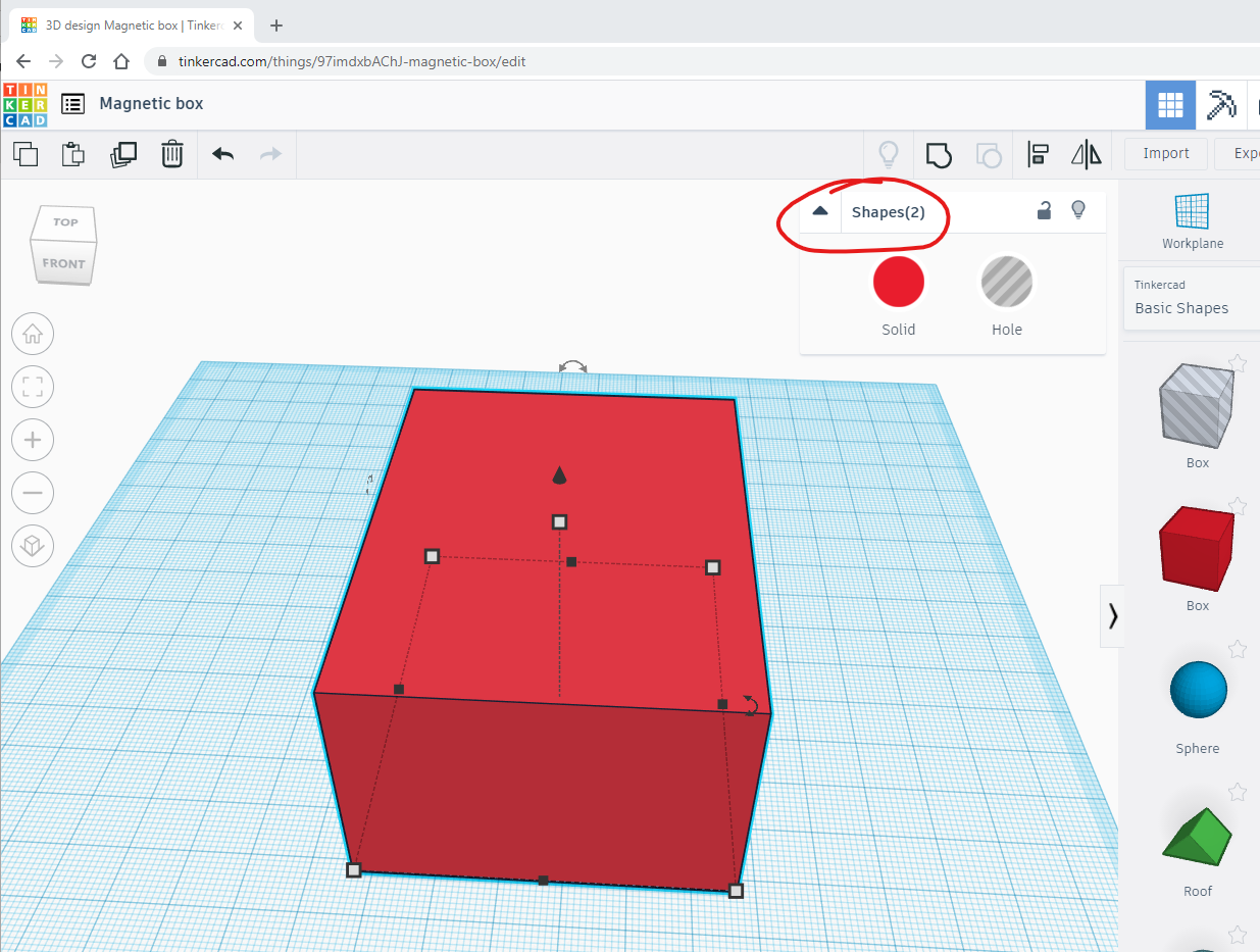
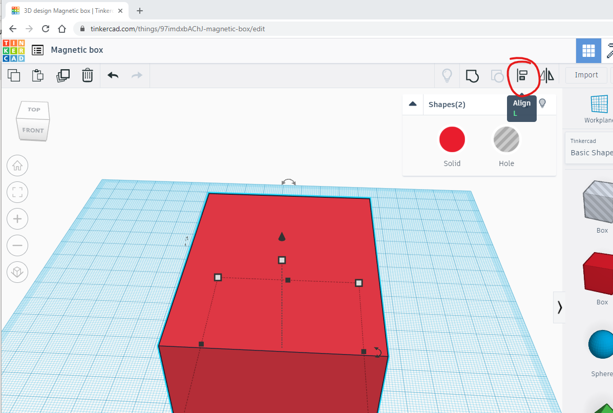
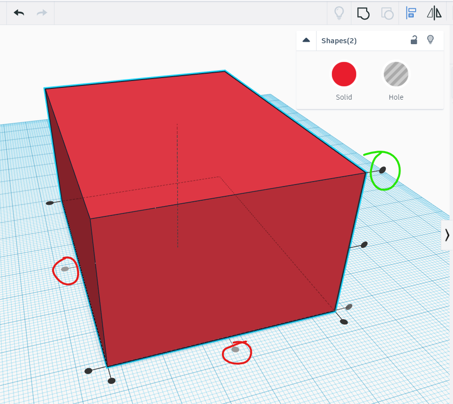
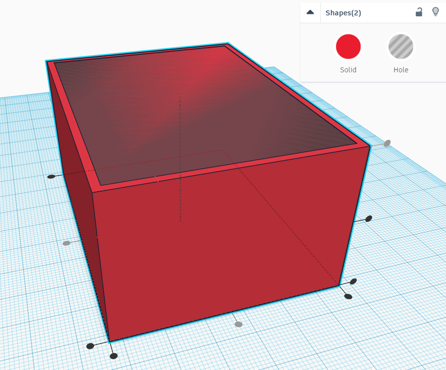
In this step we need to align the boxes so that we achieve the desired result. Select both boxes by clicking on the Workplane and dragging your mouse over both the boxes. You should notice a thin rectangle as you drag and once you have released the mouse you should notice that the properties box will show that two shapes are selected as shown in the next image (as highlighted). Click the Align button (or L key on keyboard) as shown on the third image, after which you should see the aligning handles (the little black circles) as shown in the fourth image where I have highlighted the important handles which need to be clicked to achieve the desired results. You will also notice that the middle alignment handles for length and width are grey - meaning selected shapes are already aligned on that position. This should be the case if you didn't move the shapes in a previous step. If they are not, click on them as well as the top alignment handle for the height (highlighted in green in the fourth image). This will bring the hole box at the top surface as shown in the fifth image.
Note: As you can see from the 4th and 5th images the alignment handles are on the outside/solid box. If you find that they are not as shown (i.e. they are on the inside/hole box as demonstrated on the sixth image) then just click on solid box before you click on any of the alignment handles. This means we want to align the inside/hole box to the outside/solid box and not the other way round.
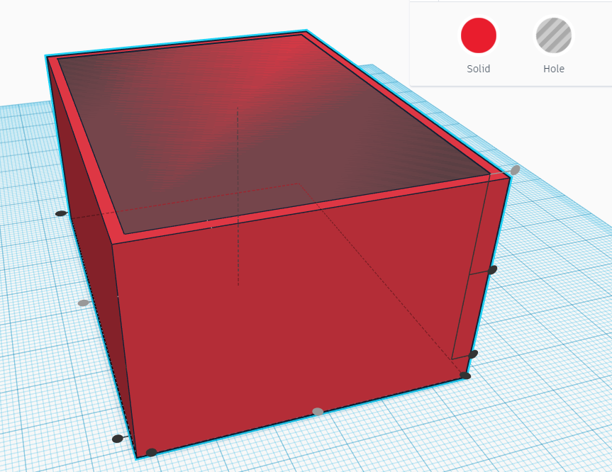
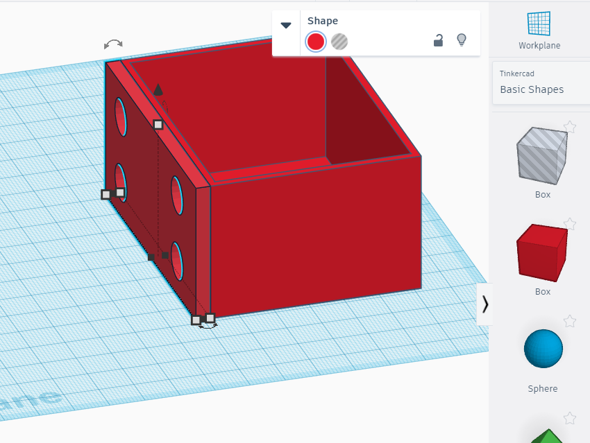
Make It Hollow
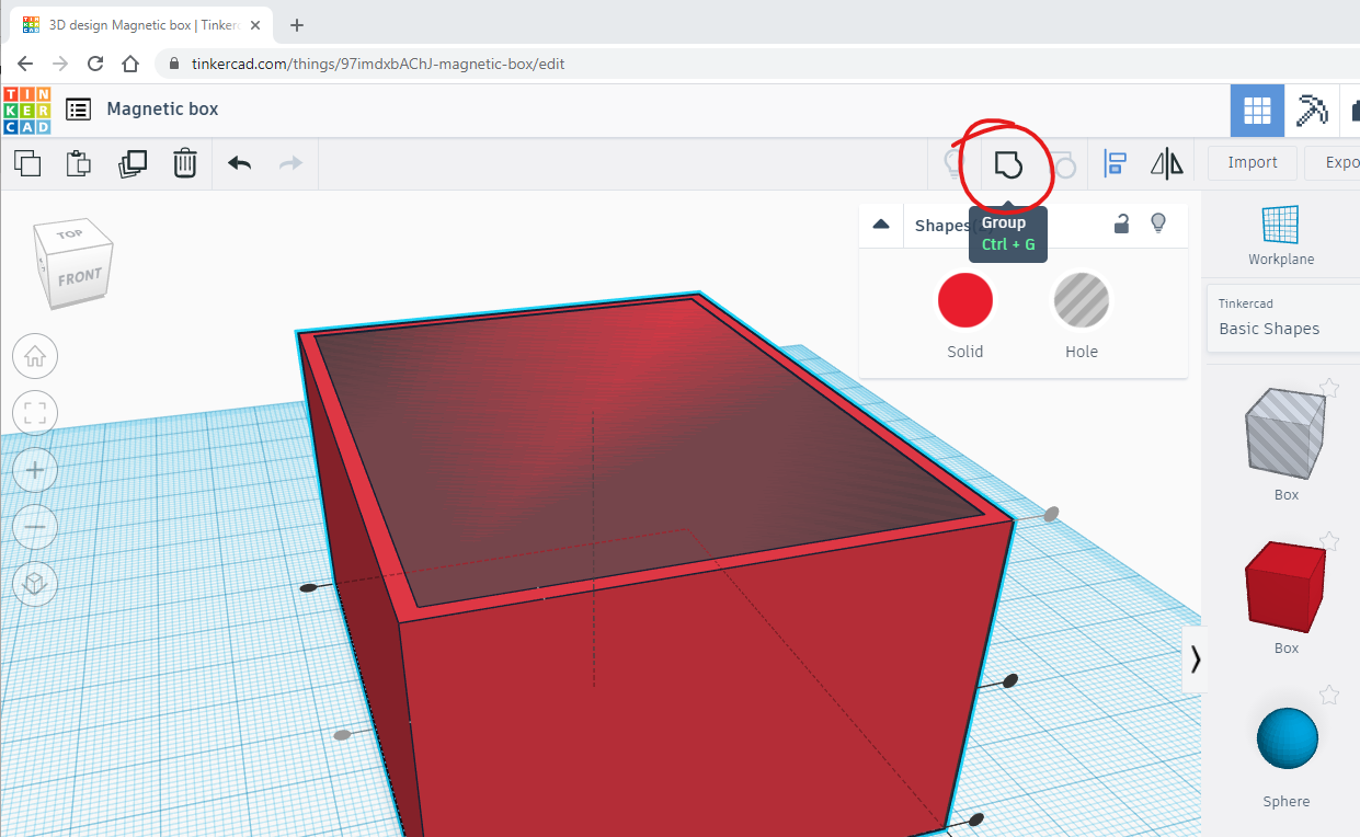
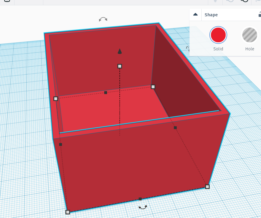
At this point with the boxes still selected click the Group button (or Ctrl + G on keyboard) to group both shapes into one creating a hollow box as shown in the images.
Create Another Box
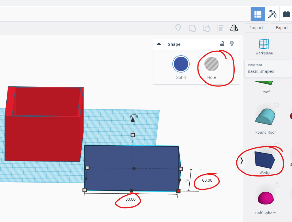
We have a box but no-where for us to attach magnets. In the following steps we will create the places for the magnets. For this we will need another box as in Step 2 but with different dimensions depending on the height of you magnets and I guess their diameter also. However I am using four magnets with 10mm in diameter and 3mm height. You can go with 2mm magnets but I don't recommend going with smaller magnets than 10mm in diameter as they can be tricky to handle plus they provide less magnetic surface. By all means if you don't have the size given and only have smaller ones then adjust for the number of magnets you should have. Additionally you will need to consider 3D printer tolerances and adjust for this accordingly. For my magnets above (10x3mm) I just add 1mm to both diameter and height which allows for the magnet to fit snugly in and accounts for a bit of glue that we are going to use to stick the magnet to the box.
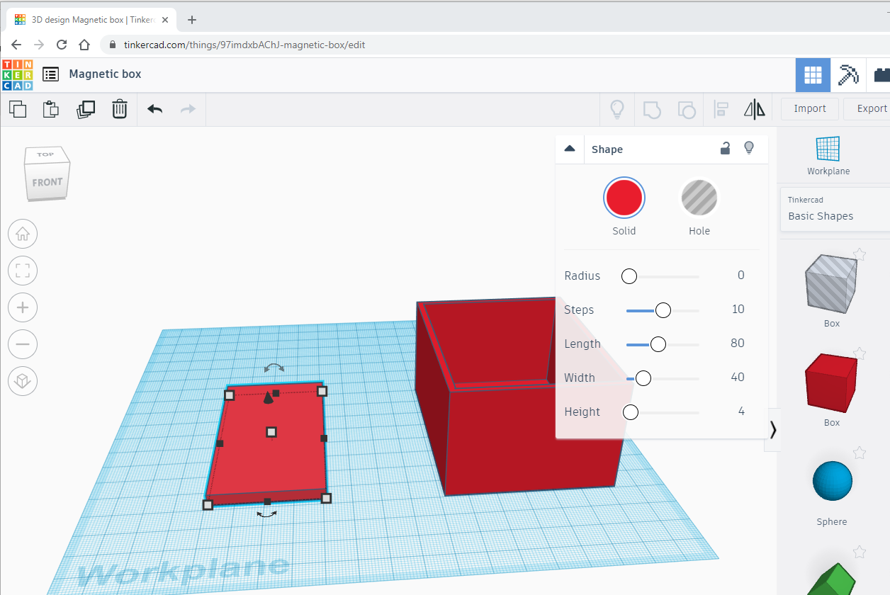
So taking the above into consideration we need a box in a rectangular shape with these dimensions: width = 40mm, length = 80 and height = 4mm. As you can see two of the dimensions correspond the previous box and the other dimension corresponds to the height of the magnet plus 1mm tolerance - if you are making your own custom box adjust accordingly.
Tinkercad is amazing and allows you to build complex shapes by building them in components and then grouping them together to create the end product. This is what we're doing here, working on a separate component for the completed box.
Drag a new solid box to the Workplane and adjust the dimensions as mentioned above and if you need to see Step 2 on how to do this. Image above shows this new box with the correct dimensions. I moved the previous box out of the way to make space for us to work with the new 'component'. To do this just click and drag to the right or the left depending on preference.
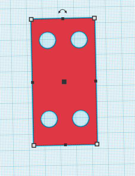
Create the Holes for Magnets
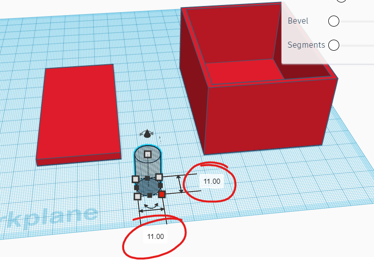
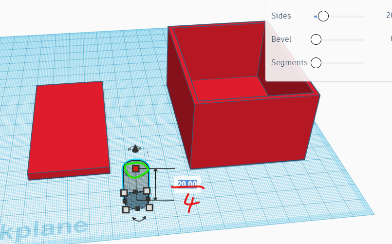
In this step we are going to make holes for the magnets. Going with the above dimensions I created 4 holes distributed evenly on each corner. If you have a bigger box or smaller magnets you might need more holes so adjust for your own needs. To create these holes we drag and drop a hole cylinder from Shapes into the Workplane and change the properties with dimensions mentioned in previous step - i.e. for my magnets this is 11mm diameter and 4mm height. To change the dimensions for the Cylinder use the size handles - first for width and length, which need to be equal to make it circle rather than oval. Best way to do this is click on the number once you have selected the correct size handle as shown in the image. Do the same for the height as well, change the height from 20mm to 4mm.
Align and Make the Holes
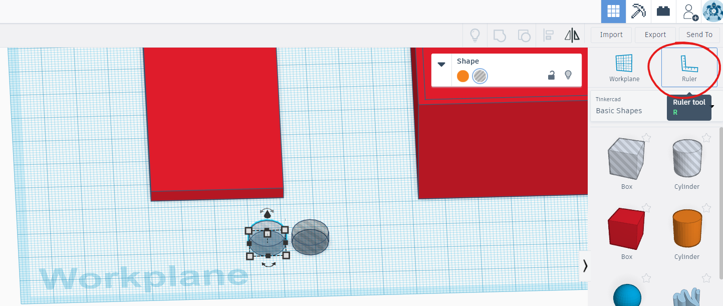
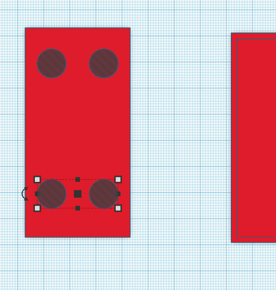
As I have already mentioned for my box with above given dimensions I am using 4 magnets. For this step you can approximate the location or use a bit of math to distribute them evenly on the side of the box. I use the Ruler to help with this and duplicate the shape we created in step 8 once and group the two of them and then duplicate this new shape again and move that on the next corner. Feel free to approximate their location if you would like - I actually wrote a long paragraph of how to do this but it became convoluted and complex to the point I was having trouble understanding it myself!!! I will try to do a video for this Instructable when I get a chance. For now see image of how I spaced the 4 magnets - to be honest when I initially created this for myself I just approximated anyway. Edit: Distributing the magnets evenly could position them too close together which might make them less effective so use your best judgment if you've used your own dimensions.
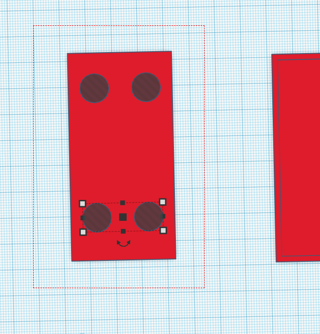
Next select all 5 shapes as shown in the image and group them together. This will create the holes for the magnets.
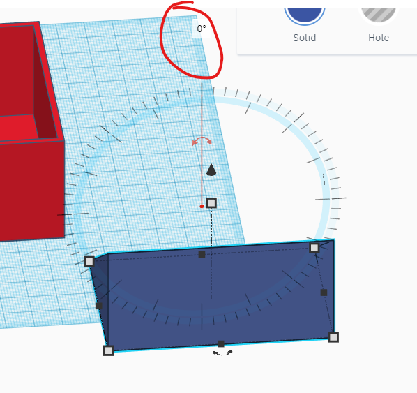
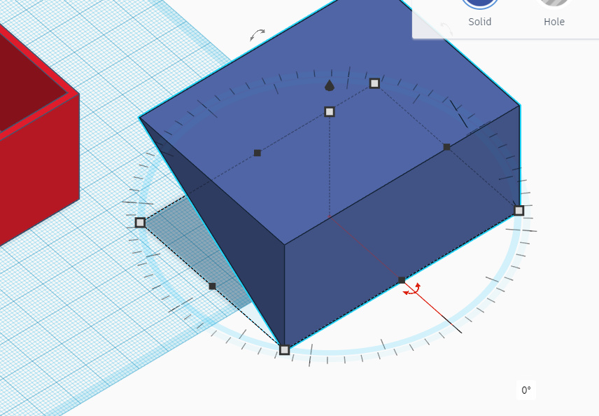
Rotate
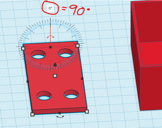
For this next step we need to rotate this new 'component' and attach it to the main box to make one whole object. Select the shape created in step 10 and rotate it as shown in the image. There is only one way to rotate it so if you make a mistake just press Ctrl +Z to undo and try again. We want to rotate by either 90 or -90 degrees. You will notice that after you rotate the shape it will be halfway through the Workplane. Press D to 'Drop' the object to the Workplane or as is our case lift it up. TIP: For more Tinkercad shortcuts head over to https://blog.tinkercad.com/keyboard-shortcuts-for-the-3d-editor
Combine the Two Objects
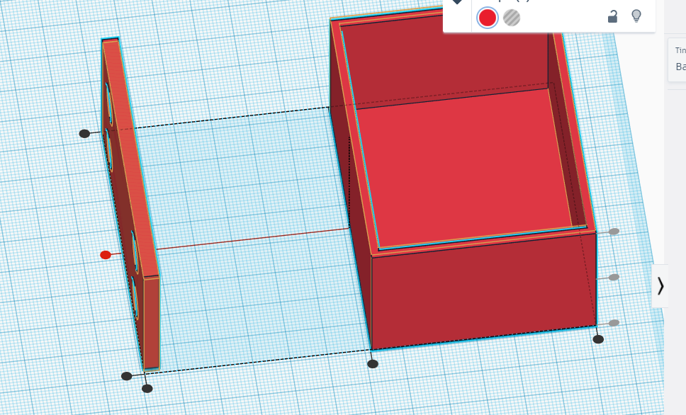
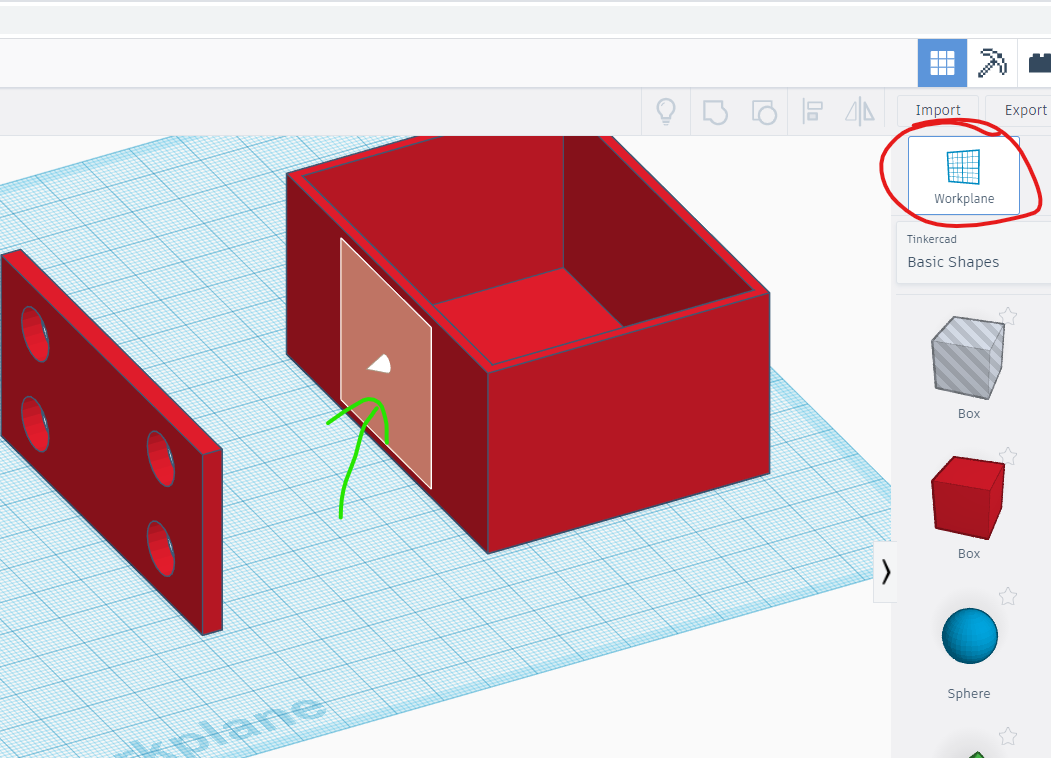
There should now be only two objects in the Workplane. Select both of them and use the align tool to align them to the centre on the length side as shown in the image. Then drag a Workplane tool on the side of the box as shown in the image. Select the other object with the 4 holes and press D key on the keyboard which will drop it on the Workplane we dragged on the side of the box. And because we have already aligned the objects they should fit 'snugly' next to each other. Drag the Workplane again anywhere to make the previous one disappear, select both objects and group them to make a new box.
At this point if you want a box then export the file to SLT (see step 13) then slice and 3D print it. The next 2 steps are optional but I did them for my box to make it look pretty :)
Make It Pretty
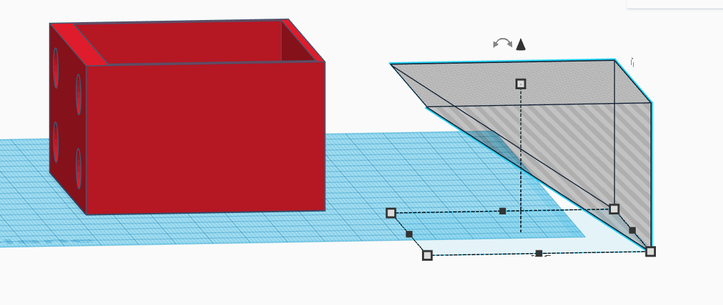
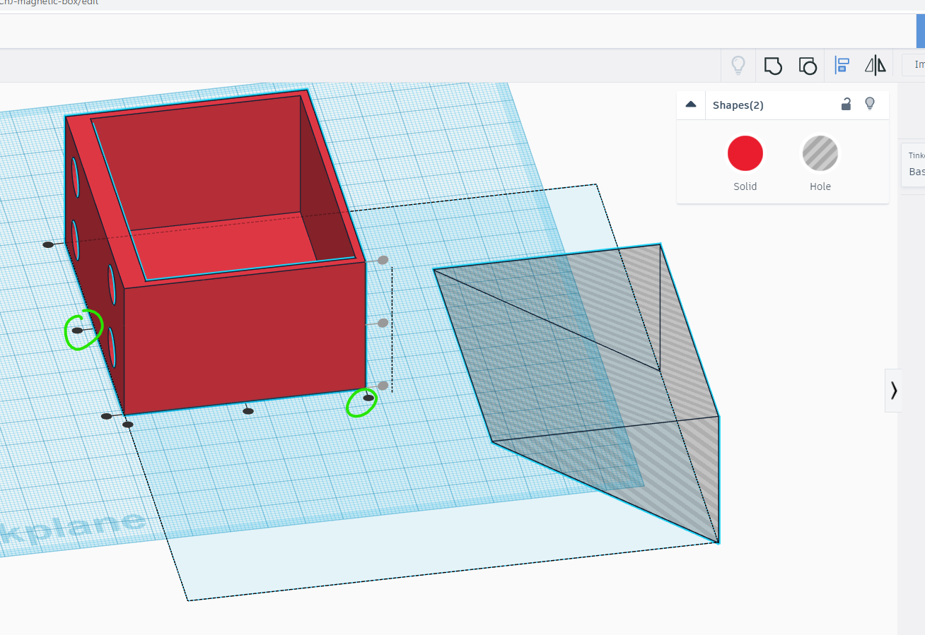
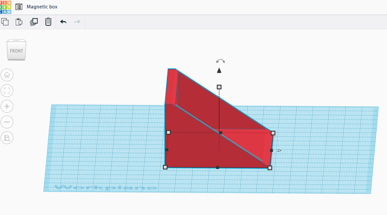
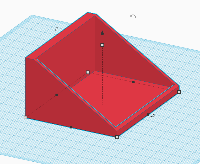
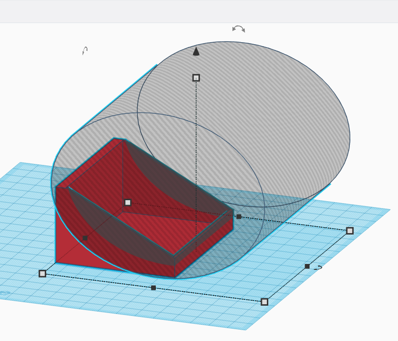
Next find the Wedge shape and drag it to the Workplane. Change the dimensions for it to be the same as the box in step 2 - i.e. W=60mm, H=40mm, L=80mm. See image, also make it Hole because we are going to use this to subtract part of the box. Next we need to rotate this by 180 degrees on length side as shown in the image. Rotate it again but this time by (minus) -90 degrees on the width side as shown in the image. Basically whichever sides you rotate we need to flip the wedge as shown. At this point we need to select both objects and then align them to each other so select the align tool making sure the handles are on the box and not the wedge. We want to centre the wedge to the box on the length side and align the outer side i.e. not on the side where the magnets are meant to be as shown in the image. Then you need to group these two objects to get the end product (object). If you prefer you can adjust the width and height of the wedge before you group them in this step to get a different look which is what I did initially with my first design. Use the align tool to align on the correct side to get the desired effect. An alternative design is also shown with curved design and for this I just used the 'trial and error' method! i.e. adjusted the cylinder dimensions until I was happy with the design after grouping the objects.
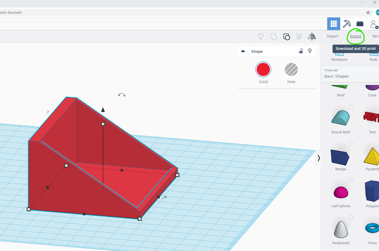
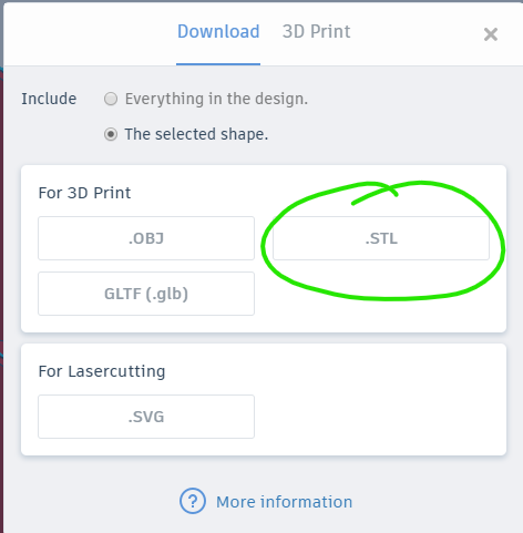
Export and 3D Print
.jpg)
To export click on the Export button and select STL as shown the in the images. Save and 3D print the file.
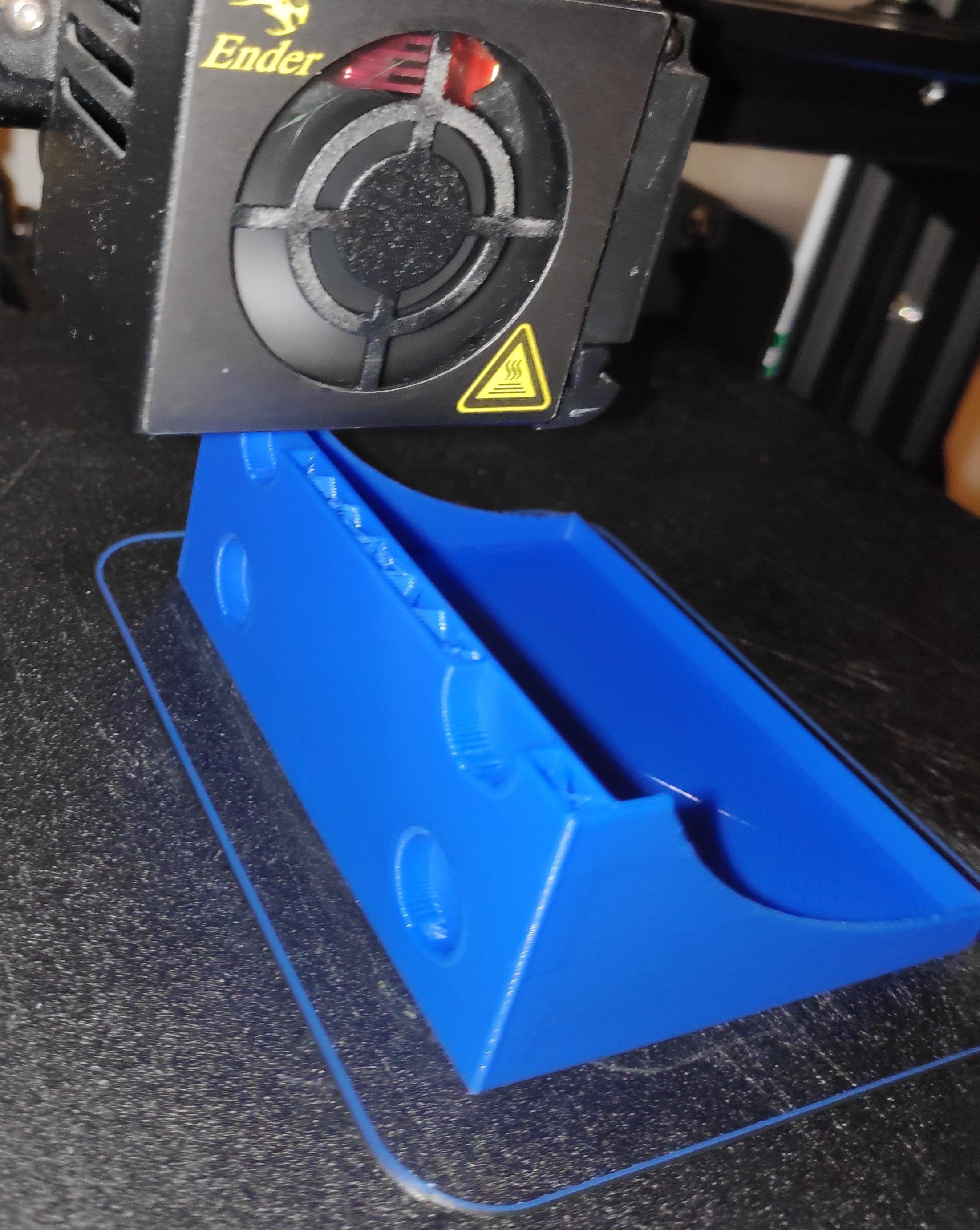
Attach the Magnets and You're Done!
.jpg)
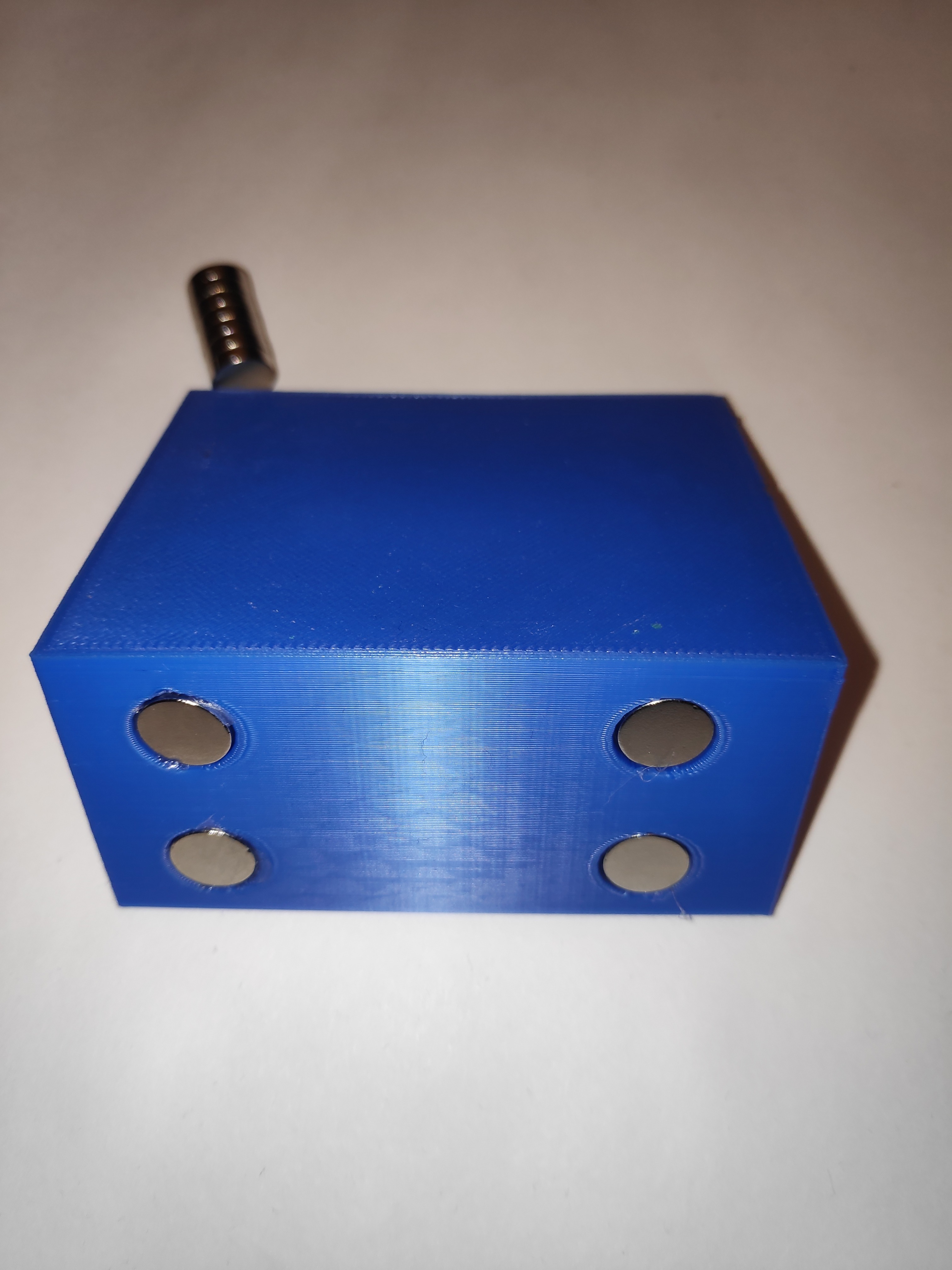
Fire up your hot glue gun and take care because its hot as you know! Estimate to put enough glue so that the magnets sit under or at the same level on the side of the printed box but do not stick out. I basically just drop one small smidgen of glue on one hole then press the magnet firmly in.
As you can see from the end picture I was a bit too quick with pressing the magnet in while the glue was still very hot - give it a couple or so seconds for it to cool down a bit.