Skull Speaker Easy 3D Print
by thomasetbaylor in Craft > Fiber Arts
554 Views, 1 Favorites, 0 Comments
Skull Speaker Easy 3D Print
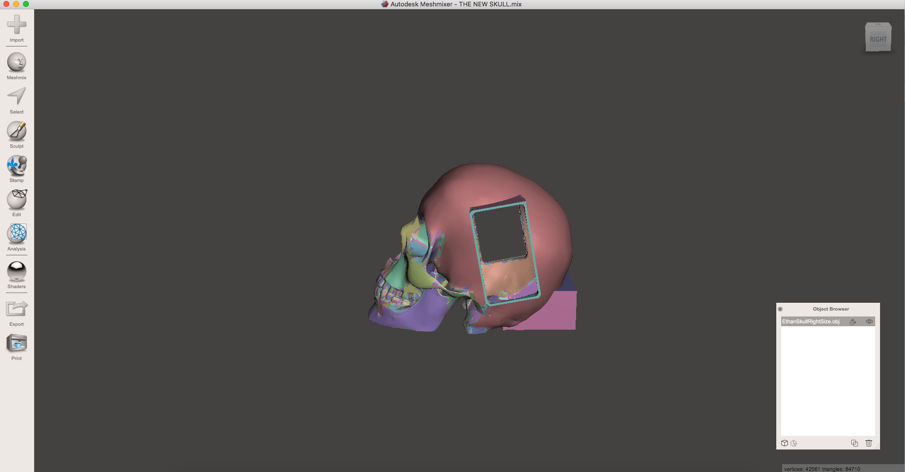
In this instructable, i will show you how to hollow out a solid model, split a model into separate pieces, and edit and transform a model to fit your design. We will be using two free programs for this tutorial, Meshmixer and Sketchup.
Transforming Your Model
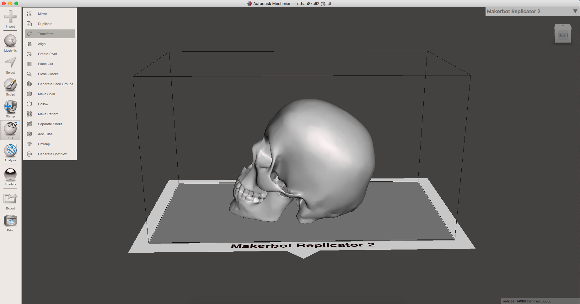
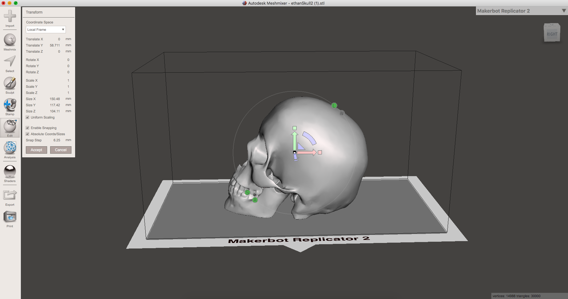
I got the inspiration for my project from my teachers artwork and his previous 3D prints. I asked him if i could borrow the model he used for these and he was glad to help. When I first opened up the model in Meshmixer I noticed that the scale of the model was a little smaller than I liked. In order to scale the models size in uniform you must first go to EDIT then to TRANSFORM. Once in TRANSFORM be sure the have your Coordinate Space set to Local Space, and your scaling set to uniform. You should now have three arrows on your screen indicating a 3D Cartesian Coordinate System. In Meshmixer the Y will be the green arrow, X will be the red, and blue your Z. The max Y distance "height" on my printer was 150mm so I made that my Y.
Adding Additional Parts to the Model
To begin this process first go to MESHMIX, then select the Cube shaped model and drag it onto the screen. once you have done this we will now transform the cube to fit our size of speakers using the same steps as earlier, and then place the modified cube inside our model. The dimensions for the speaker that i used were Y - 50mm X - 90mm Z - 140. Next i made sure that my Z "Blue" Axis was at 0 so the cube was centered with my model. Next I used the Y "Green" Axis to move my speakers up and rotated them with the Z. Repeat this process for any additional parts you would like to add to your model. Also, make sure to have the dimensions of the additional hole/part 2 mm wider than needed, this is so our hole size is equal to the part needed to be implemented.
Joining Additional Pieces of the Model.
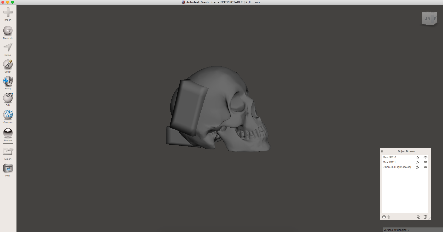
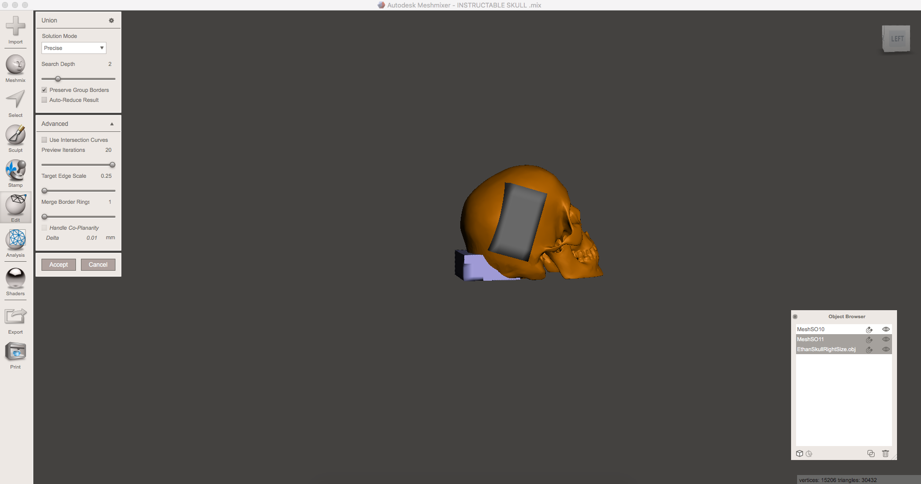
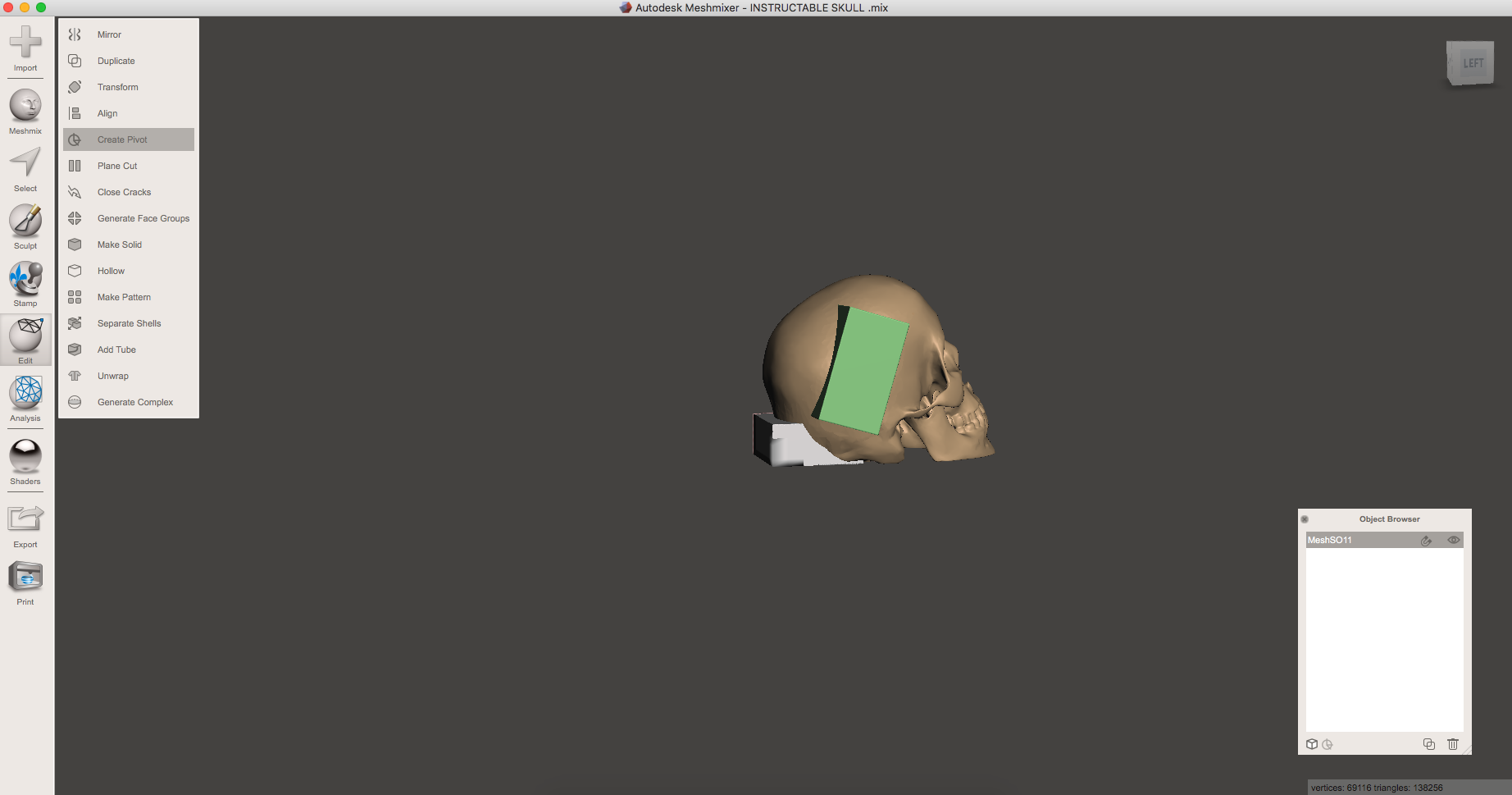
Once all of your additional pieces are in place, go to view in meshmixer and select "Show Objects in Browser". Now go to the object browser and select your model and one of the additional pieces by holding down shift and clicking the objects "make sure to only add one additional piece at a time". Once your model plus an additional object have been selected, use the Boolean union option on the lefthand side of your screen.
The Union settings should read
Solution mode : Precise
Search Depth : 2
Preview group borders : checked
Auto Reduce Result : not checked
The Advanced Settings should read
Use Intersection curves : not checked
Preview Iterations : 20
Target Edge Scale : 0.25
Merge border rings : 1
Handle Co-planarity : not checked
Once finished hit accept.
Repeat until all parts are joined.
USE THESE SAME SETTINGS FOR JOINING ALL ADDITIONAL PARTS TO THE MODEL.
Hollowing the Model
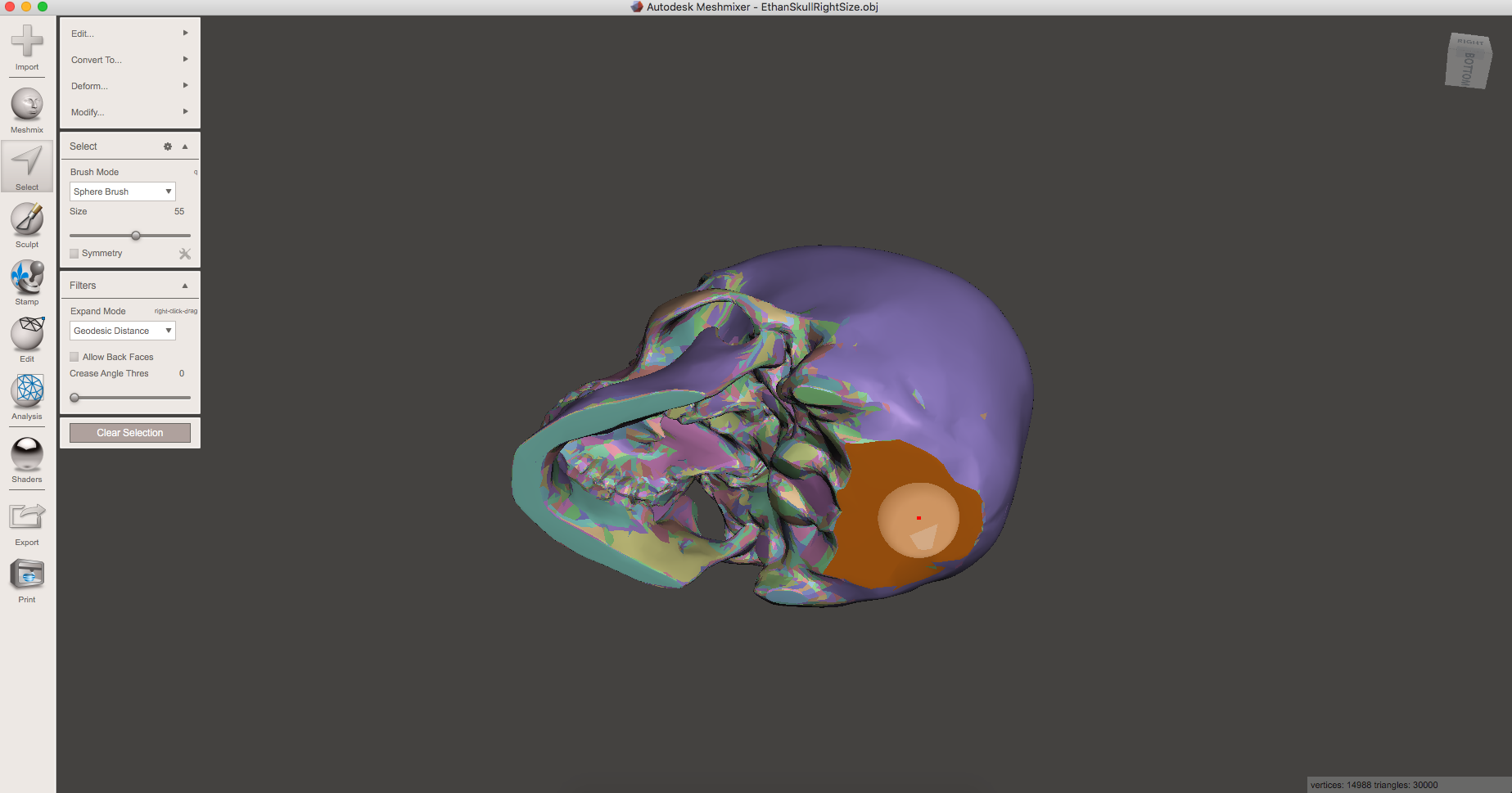
To start hollowing out your model you must first go to EDIT then GENERATE FACE GROUPS. Once in GENERATE FACE GROUPS switch your mode to Normal Angle, then put your Angle Threshold from anywhere in between 25 and 10, "or whenever the area on the bottom of your model is a entirely different color than the rest of the model" and leave your Size Threshold at 0. Once you have done all of this you can then move to flat surface on your model and use the SELECT tool on the left side of the screen and double click the area. Once the area is selected go to DEFORM, then TRANSFORM. Drag the selected area out on the axis that the flat face of the model points to. once you have dragged out a flat portion of the model select the flat portion of the model you just removed. then go to EDIT and HOLLOW. LEAVE ALL OF THE SETTINGS ALONE AND HIT ACCEPT. once it is done remove the part of the model you dragged out using the plane cut tool located in The EDIT SECTION. your model should now be hollowed and ready to print.