Ossein Lavallier: 3d Model to Physical Object
by kickice82003 in Workshop > 3D Printing
5449 Views, 24 Favorites, 0 Comments
Ossein Lavallier: 3d Model to Physical Object
Created by Dan Greenberg USF SACD
INTRODUCTION
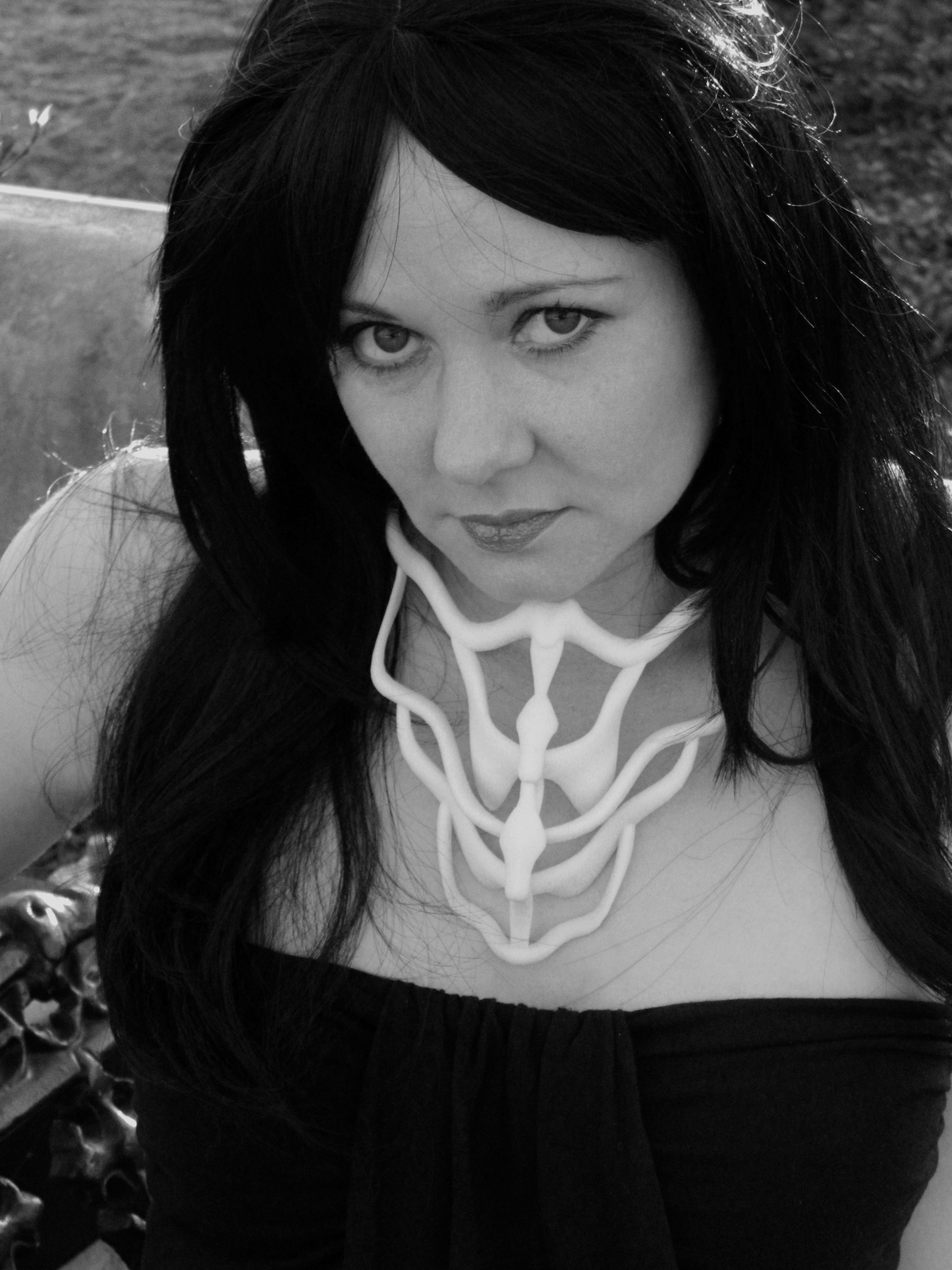
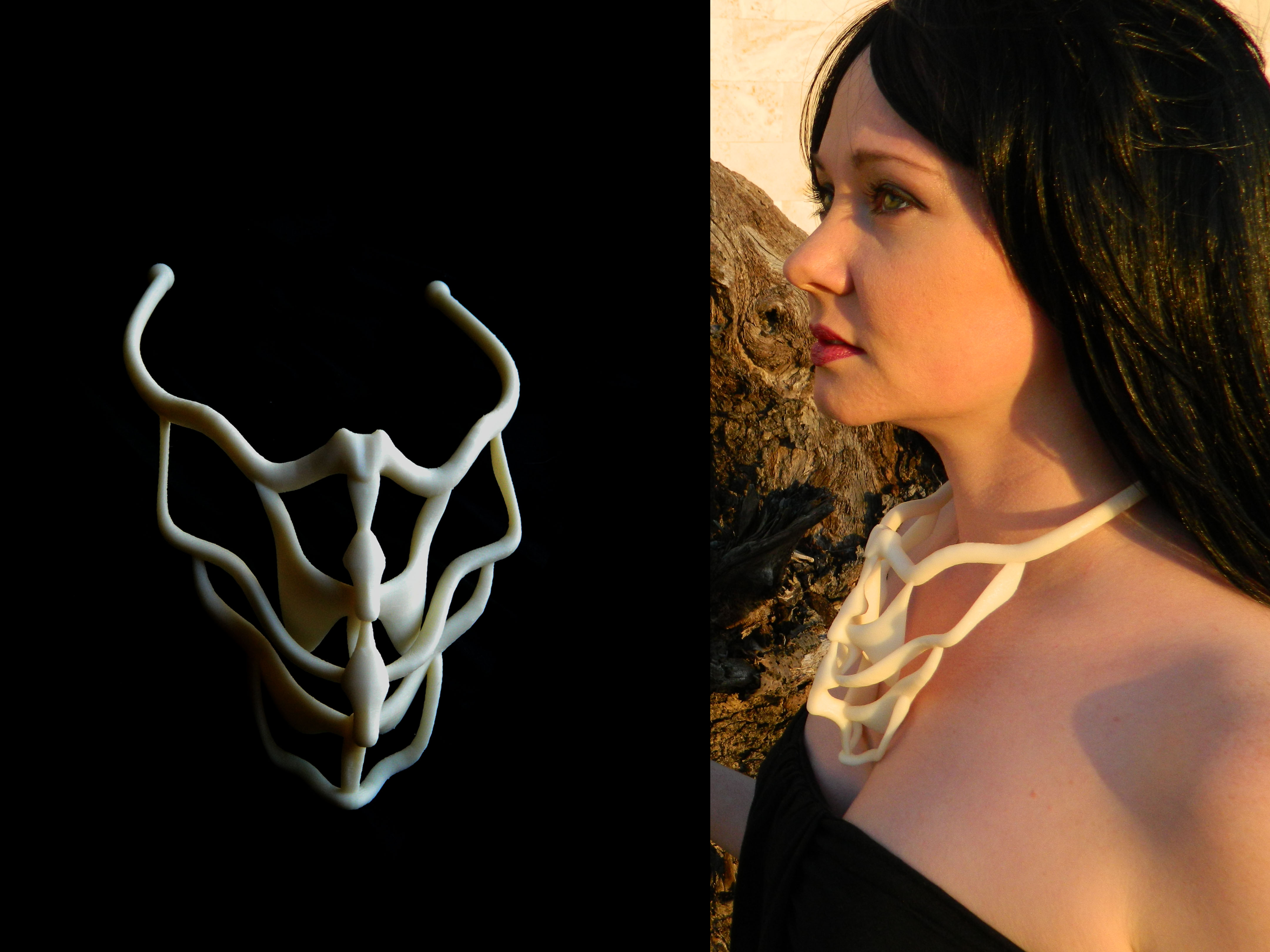
This project was born of a desire to try my hand at modeling an object in 3D and then bring that object to life using a 3d printer. The Ossein Lavallier (Ossein meaning bone and Lavallier meaning necklace) is the result.
In the steps that follow, I will attempt to explain the creation of the 3D model in Rhino and the resulting physical object printed in 3D. It is my hope that after reading this, you too will be able to create something similar and of your own design.
If I had to guess, I'd say the model took around 8 hours to create in 3D, with a learning curve. The physical model took 15.5 hours in the printer. I am new to Rhino so I am sure that the 3D model could have been completed much more efficiently.
This tutorial assumes at least a beginner level of familiarity with 3D modeling and Rhino, with the user having played around with the basic commands. Prior to undertaking this project, I had used Rhino for roughly 6 hours, so something of this scale is certainly possible for a beginner. While this is my first actual Rhino model, I have previous 3D experience in Sketchup and older versions of Maya.
FOLLOWING ALONG USING IMAGES
The screenshots have the command line in them at the top left of the image. You can look there for some more info on commands I am using. If you are attempting to model something like this, make good use of your SNAP, ORTHO, PLANAR, and OSNAP settings. I jumped back and forth through these, changing setting as needed. The tabs showing the settings for these tools can be seen at the bottom of each image.
The images tagged in each step are numbered on the lower right corner so you can follow along with the instructions.
When viewing the images tagged to each step, make note of the viewport so you do not get confused. Working in 3D is all about knowing what direction your looking in. I jump back and forth between wireframe and rendered viewports, as it useful to change the display setting of the viewport from time to time. Working in wireframe mode, switching to rendered, then to ghost, etc. helps you visualize the model better and you can see hidden flaws that may go otherwise unnoticed if you are working in just one mode all the time.
STARTING THE 3D MODEL
First, some curves need to be created. I started by obtaining some dimensions of the female neck and chest (Thank You Meagan) and used those measurements as a guideline while modeling.
I used “Curve: Interpolate Points” for my curves. These give a nice smooth line.
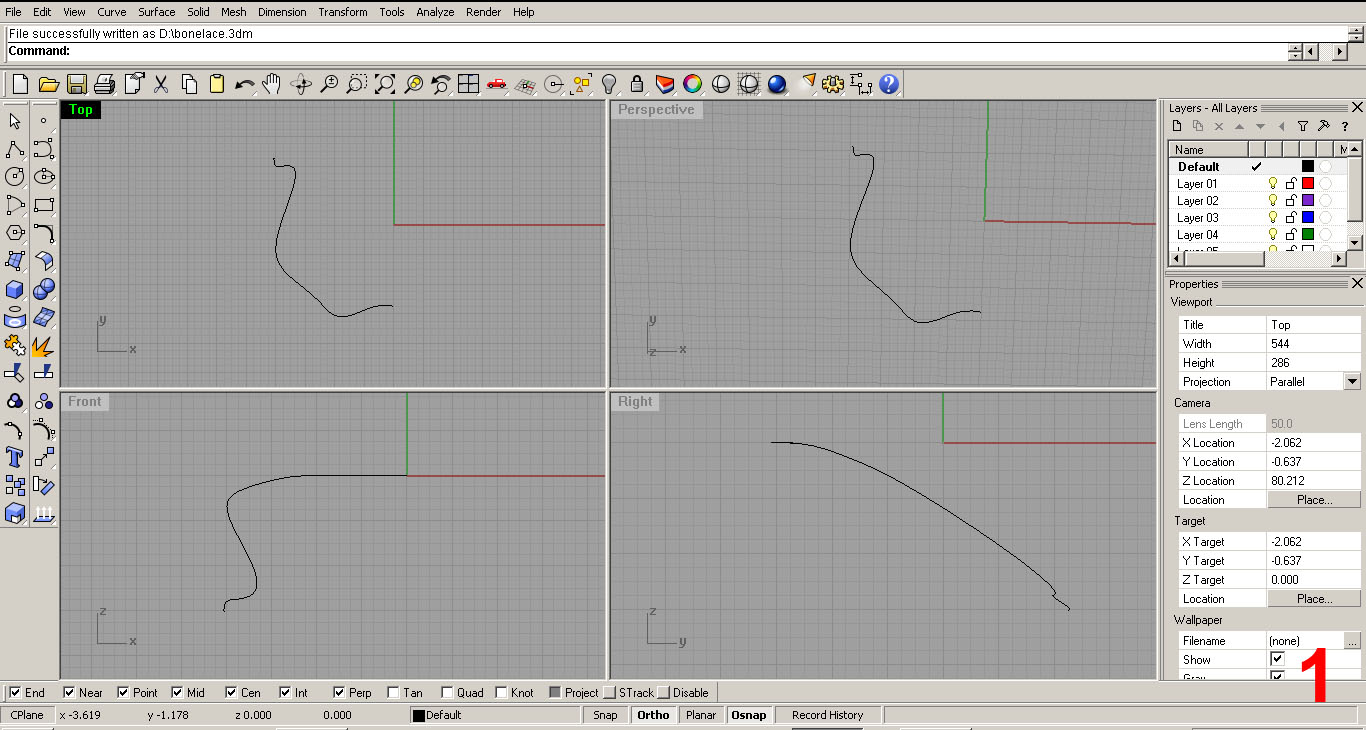
Using all 4 viewports, I drew the curve that will become the piece that wraps around the neck and shoulders. I'll call this piece the “collar or band”. The top viewport was my primary working port at this stage. IMAGE 1
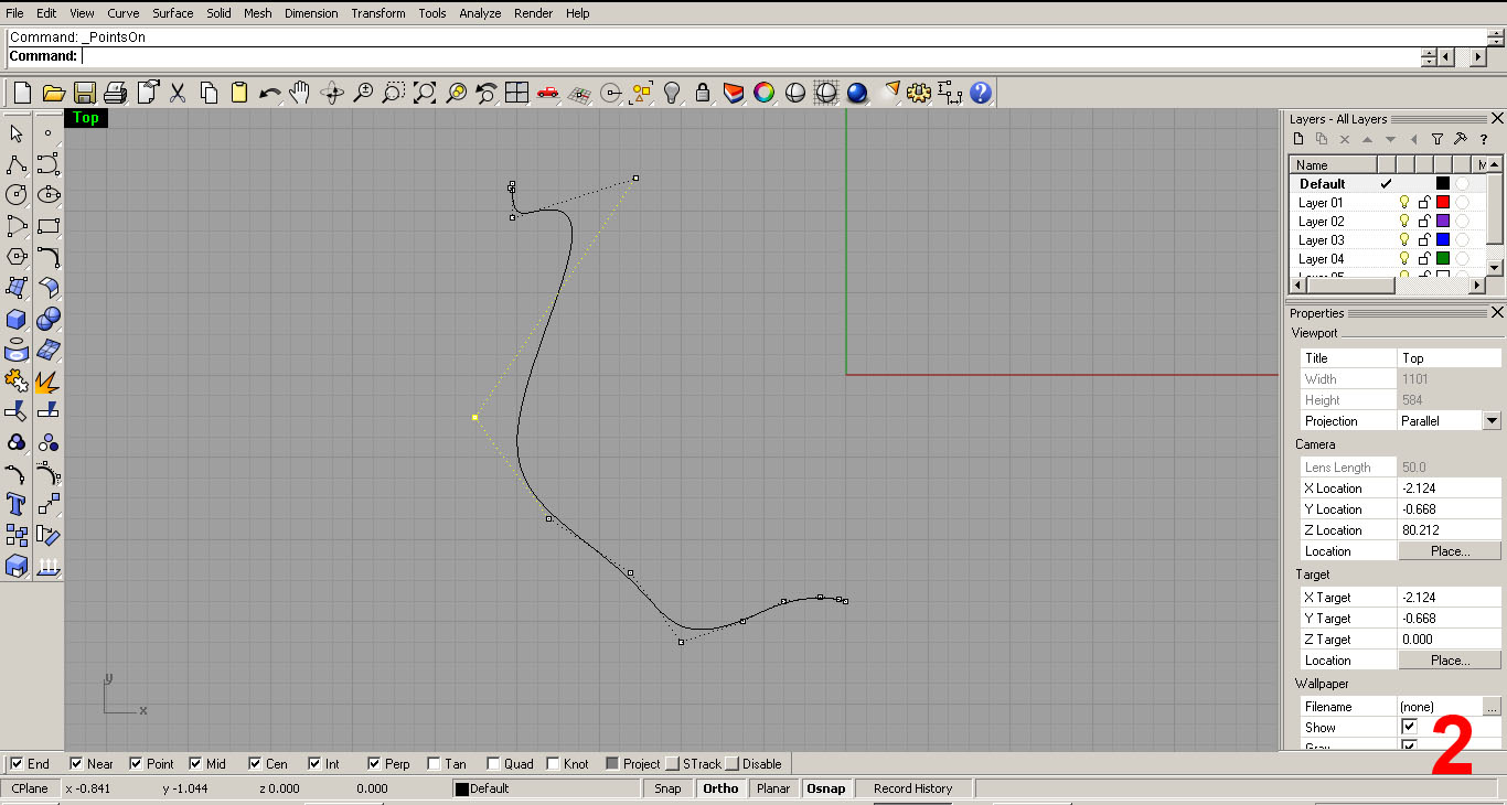
Pressing F10 to bring up control points, I adjusted the curve in three dimensions. IMAGE 2
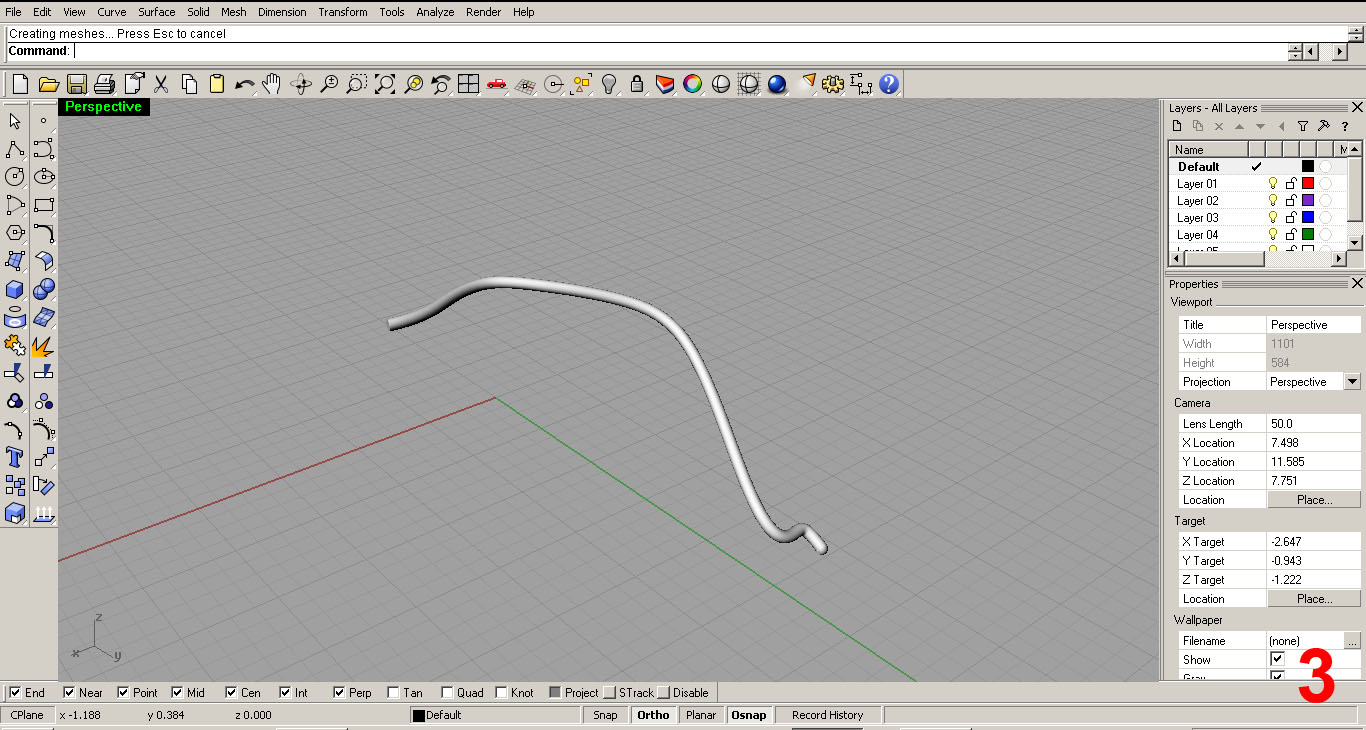
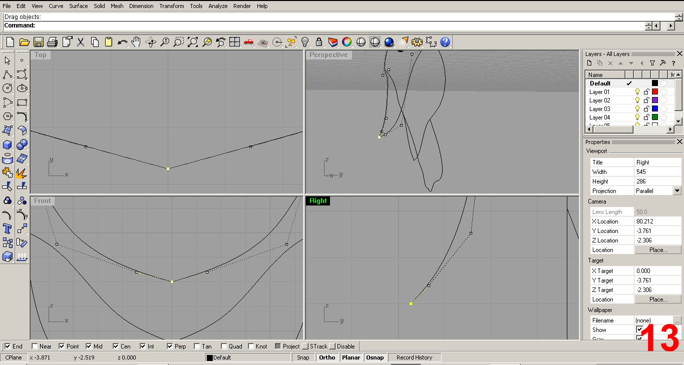
To visualize the 3D form, I used the “pipe” command and set my diameter to 3/8”. This creates a “polysurface”. Note: I then deleted the polysurface this command created, as I was just testing. IMAGE 3
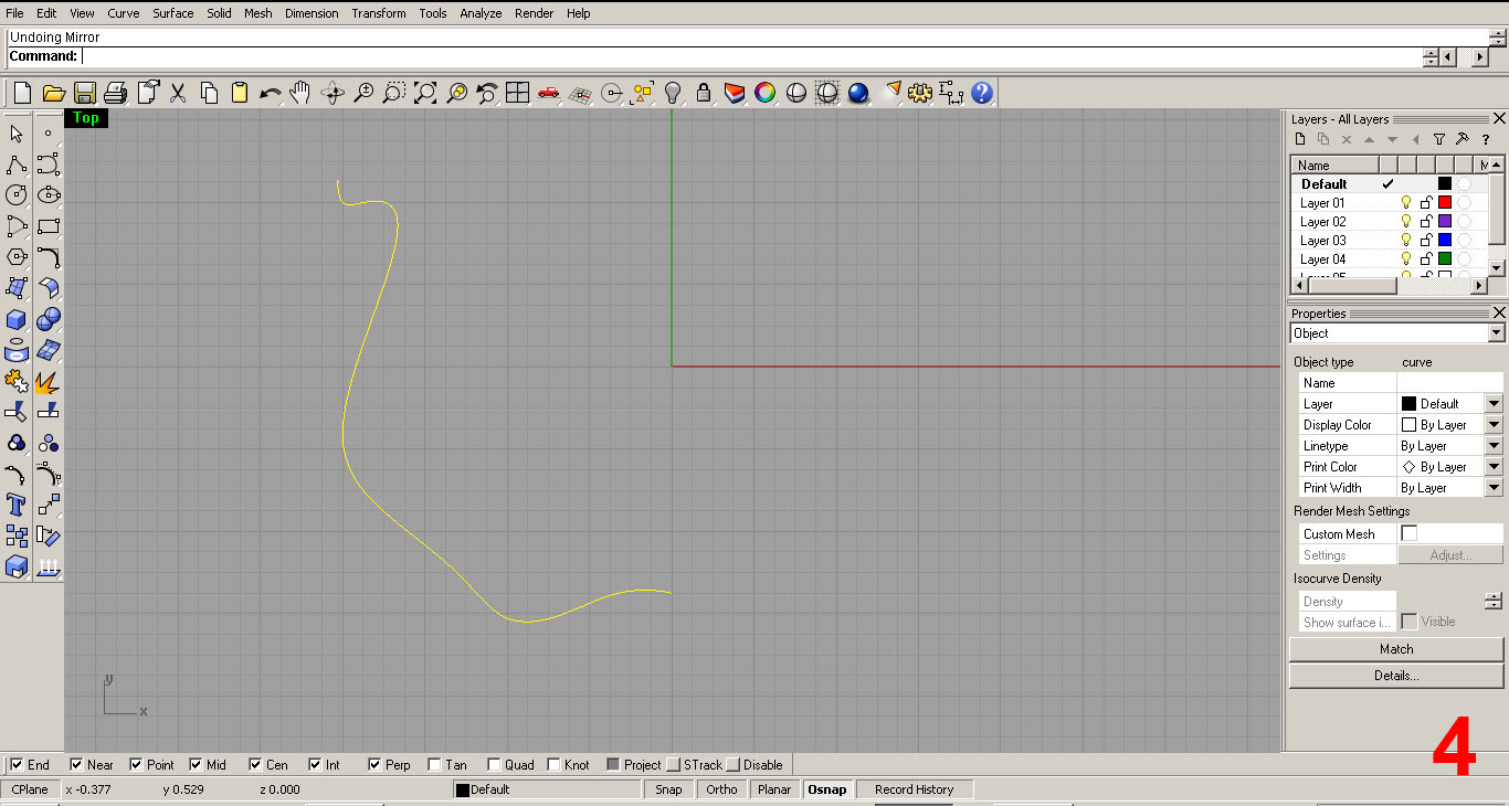
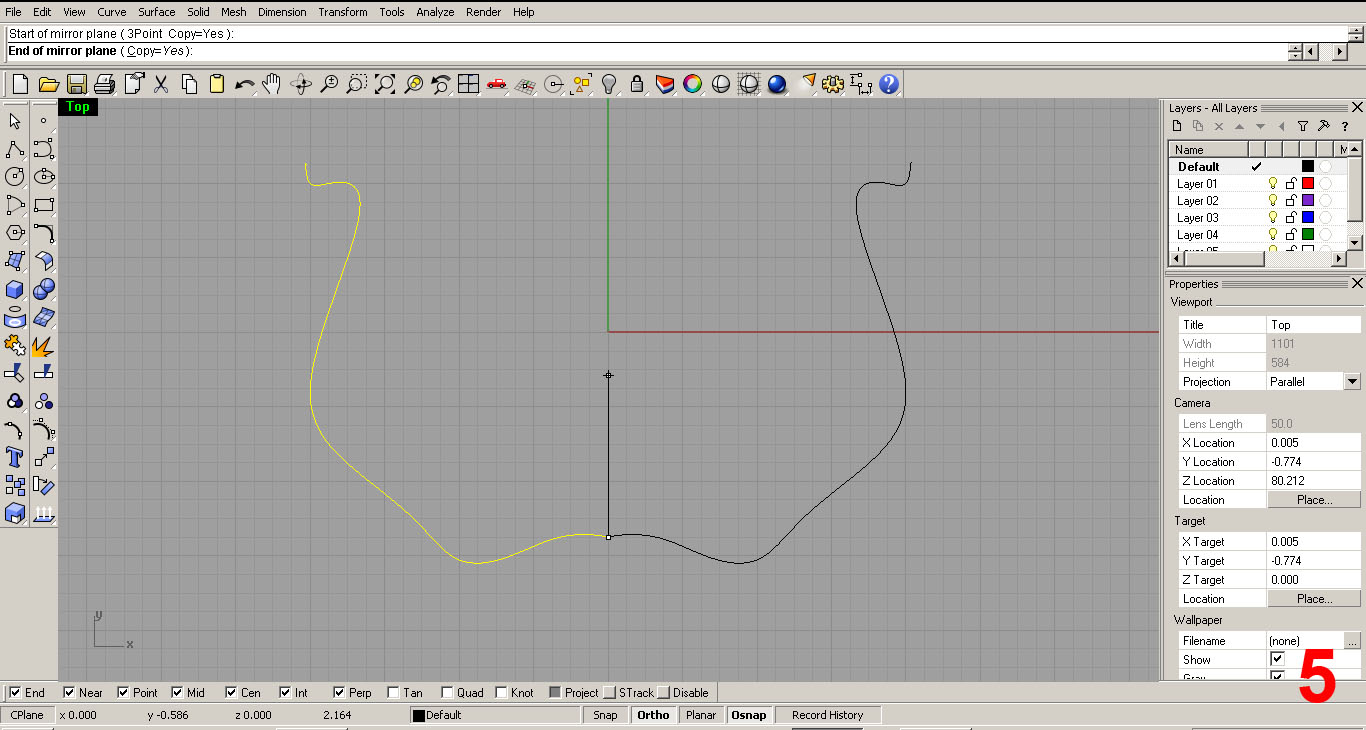
In the top viewport, I select the curve and use the “mirror” command. Selecting the bottom point, I revolve the mirror 180 degrees to make two identical curves. IMAGES 4, 5
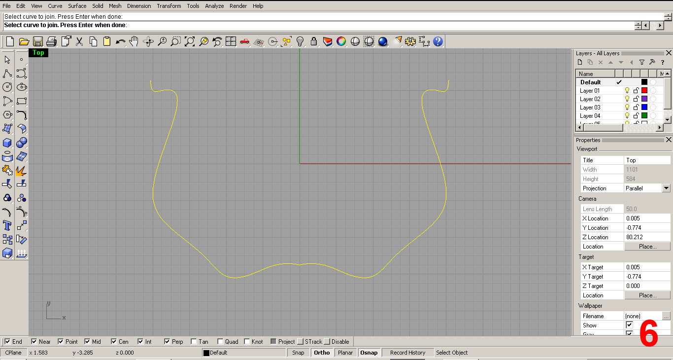
Next, using the “join” command, I created one curve from the two. Use OSNAP here. The curves need to be touching. IMAGE 6
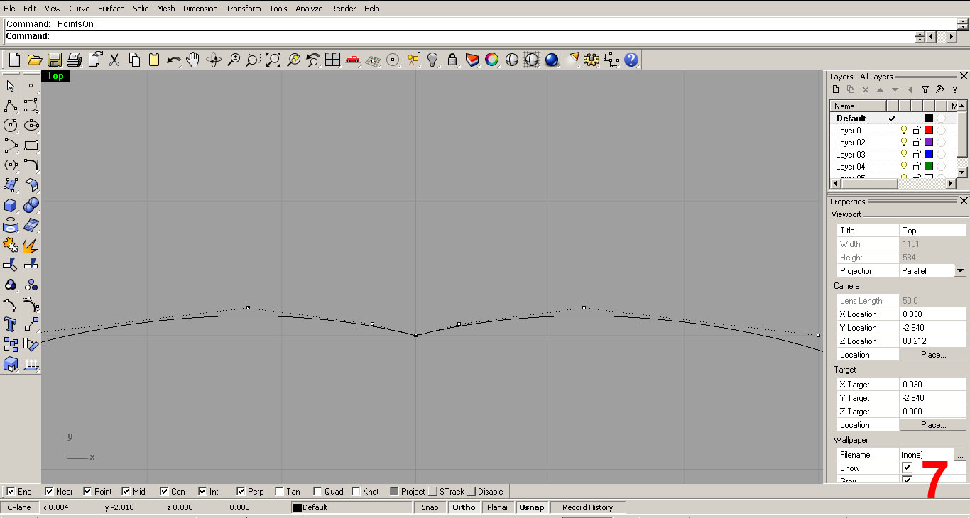
I then smoothed out the curve by adding or deleting control points to avoid “pinches” like the one seen in IMAGE 7
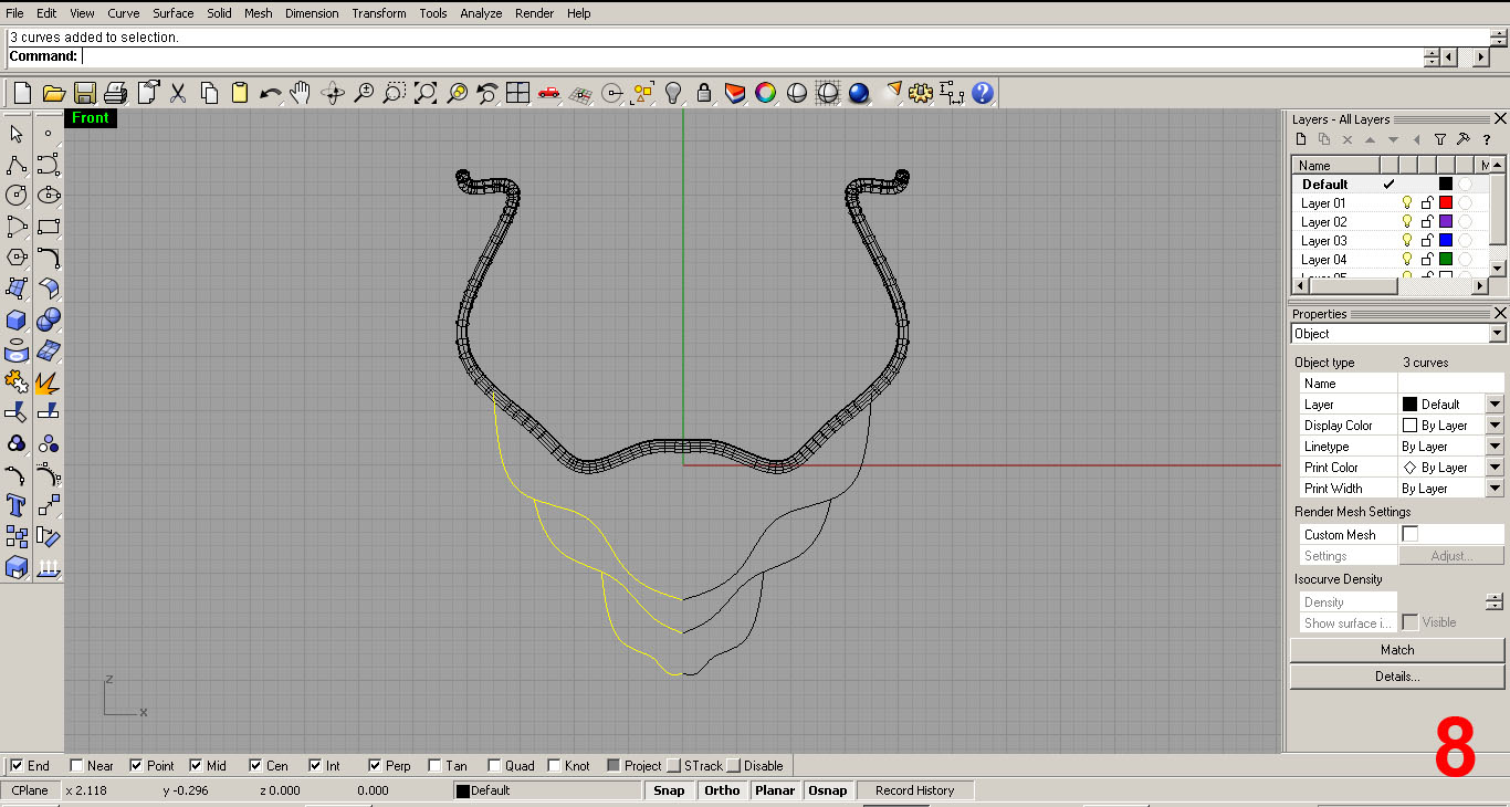
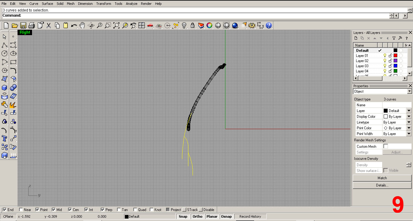
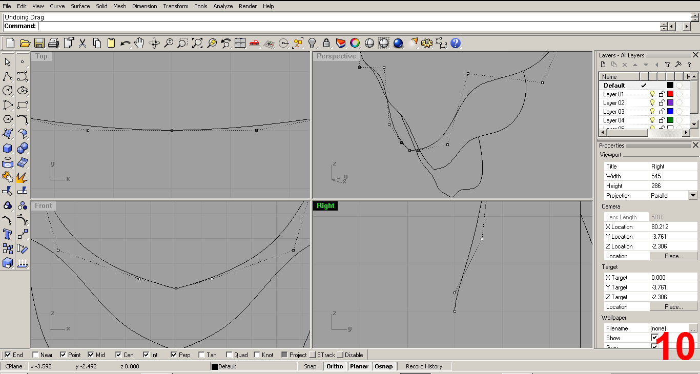
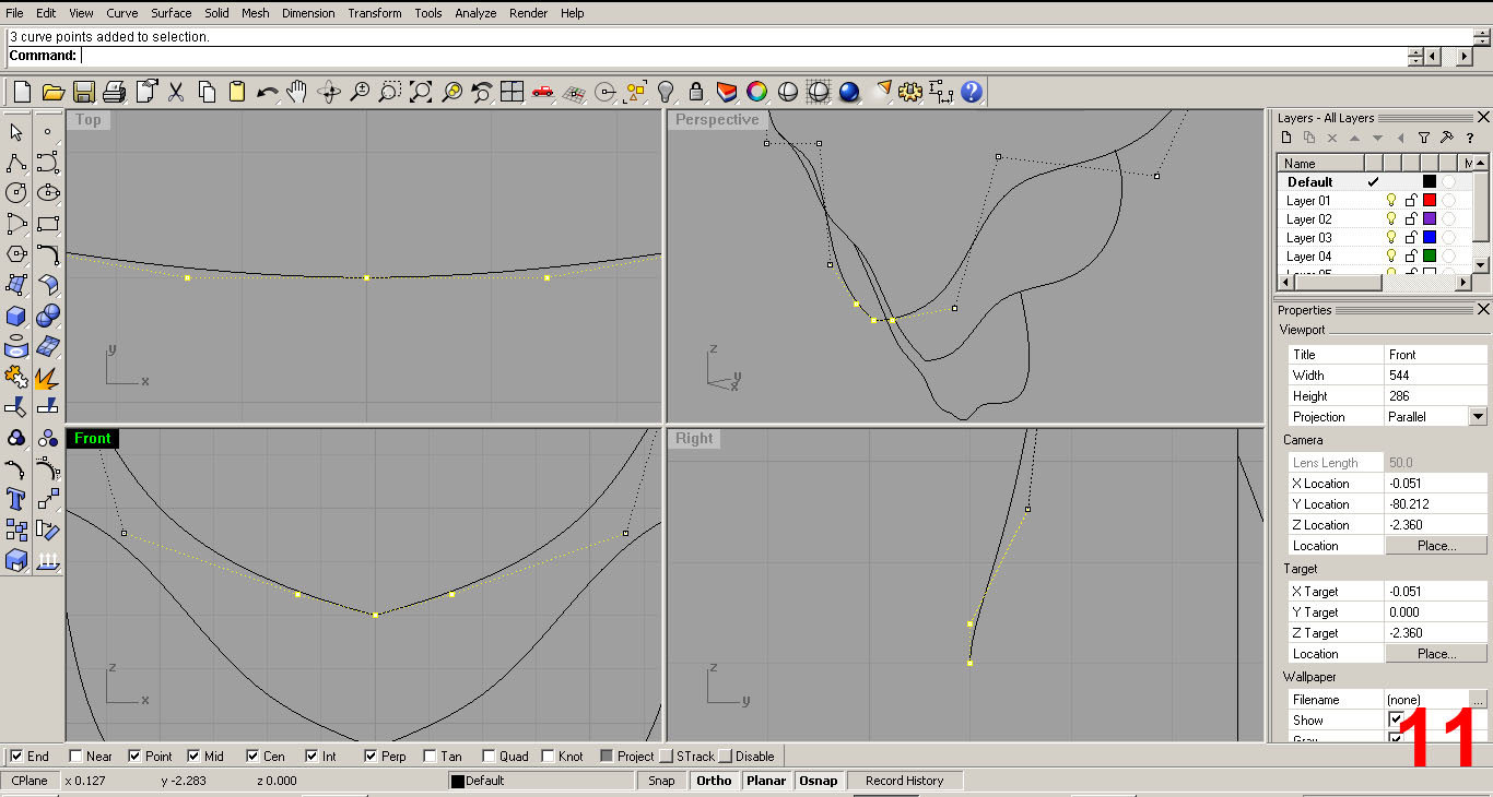
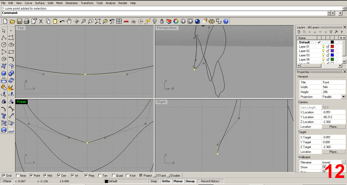
I piped the top piece once satisfied and created three more sets of curves which will form “ribs”. These curves were created in the same manner, adjusting as I saw fit using all the viewports together. I wanted to have an organic feel to the pieces once piped, so I made the curves multidimensional. Note that I have now rotated the pieces so that it aligns correctly with the viewports. The front viewport now shows the front of the model, the side shows the side, etc. IMAGES 8, 9, 10, 11, 12, 13
It is important to continuously check all your ports for accuracy during this phase. Curves where then mirrored and joined. Note: I removed the piped polysurface yet again in order to have some clarity while I worked. I'll do this throughout and I'll try to note this so you don't get scared and confused.
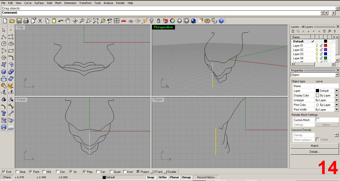
Next, I created a line 5” long so I could make sure that I wasn't wildly out of scale. My referenced dimensions: Neck diameter assumed is 5”, length of the piece in the horizontal direction is about 5” and the vertical is also 5”. All seems to be good so far! IMAGE 14
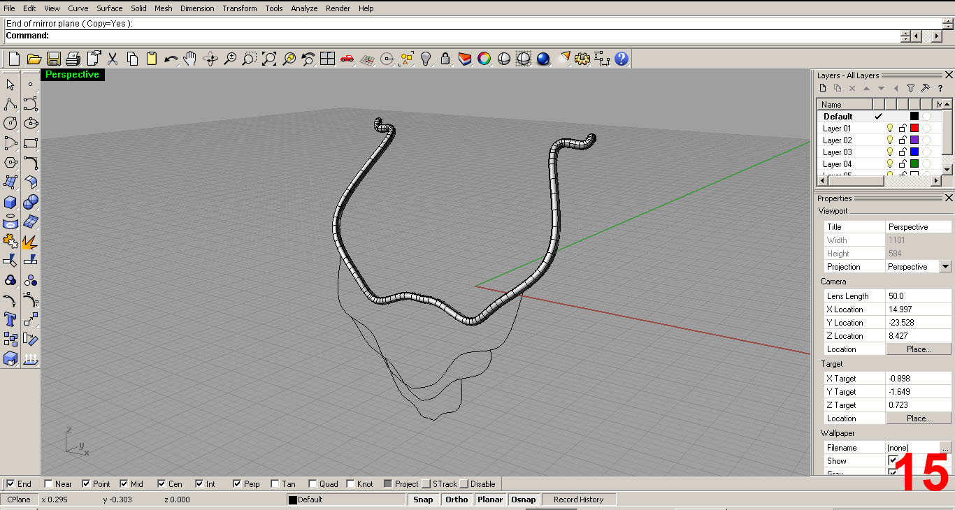
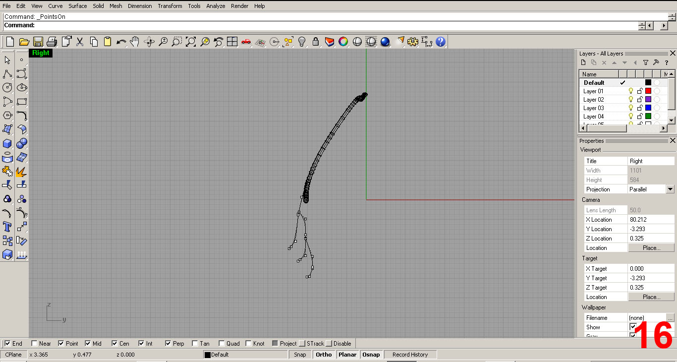
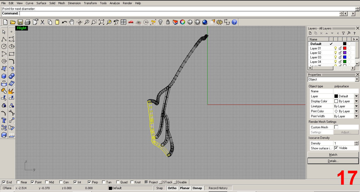
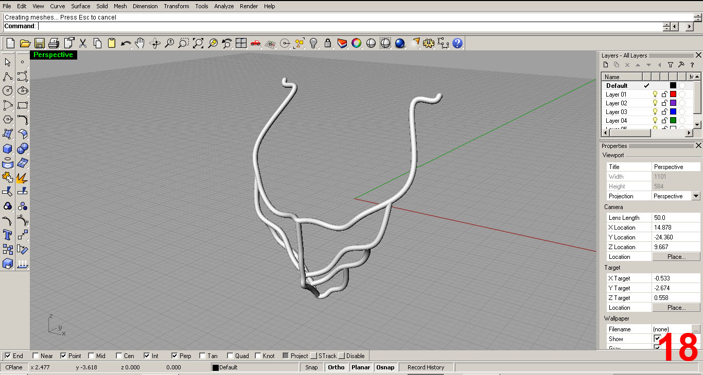
In IMAGES 15, 16, 17 I created one last curve in the center that will form the “spine”. I then piped all the curves. I used a diameter of 3/8” IMAGE 18 shows all curves piped in “Rendered Mode”.
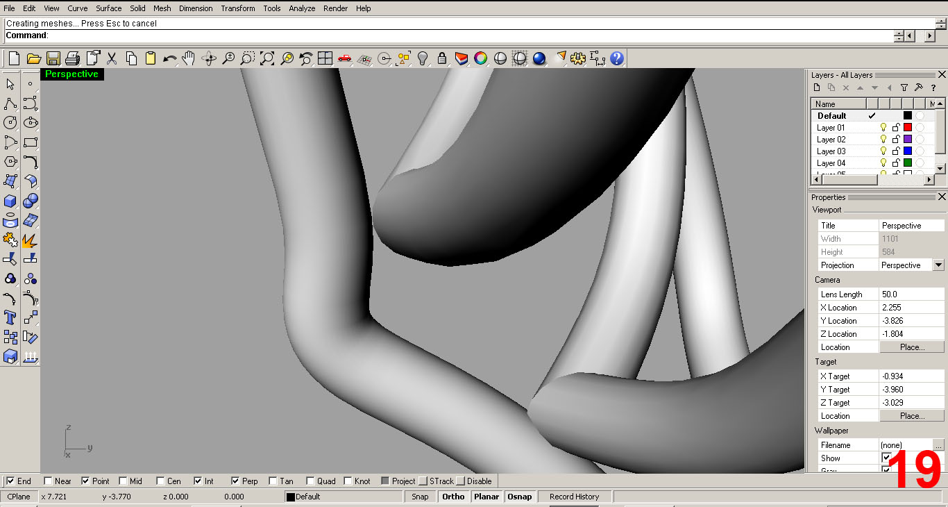
Upon close inspection of the model (In IMGAE 19) , you can see that the piped curves aren't quite touching one another. This needs to be fixed. In addition, I need to add more definition to the pipes so it looks like what is in my mind. IMAGE 19 shows the close up of the front surface moving up and away from the 3 “ribs.”
REFINING THE SPINE
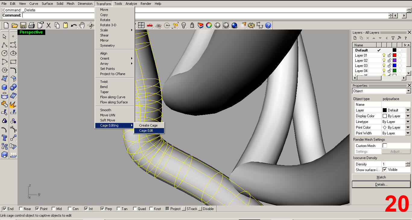
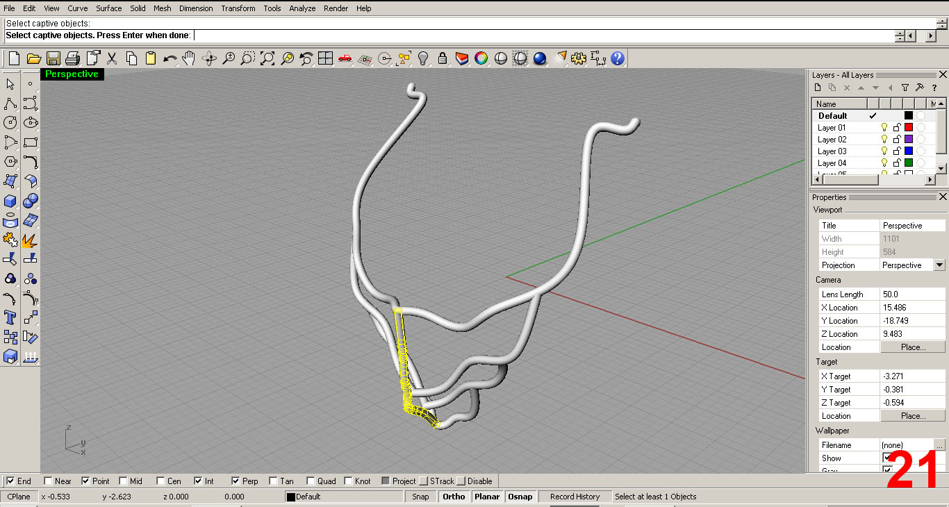
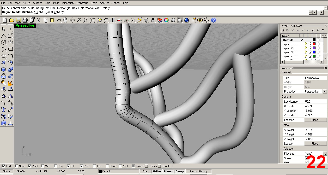
Pay attention to the command bar (top left) in these steps. The tool will ask you what surface is captive in the “cage.” This is the object that I want to edit. I select it (it turns yellow once selected) and the next query from the tool pops up...“Select control object”. My control object is going to be the very object I am editing, so I select the surface yet again. The next question the tool asks is “Region to edit”. I select “Global”. IMAGES 21, 22
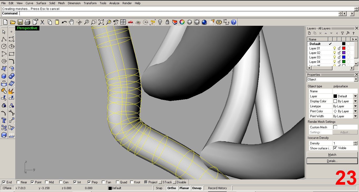
The tool now creates a mesh. If you select the surface now, it has two parts...the control and the polysurface. Select “control” and you will get a yellow cage. IMAGE 23.
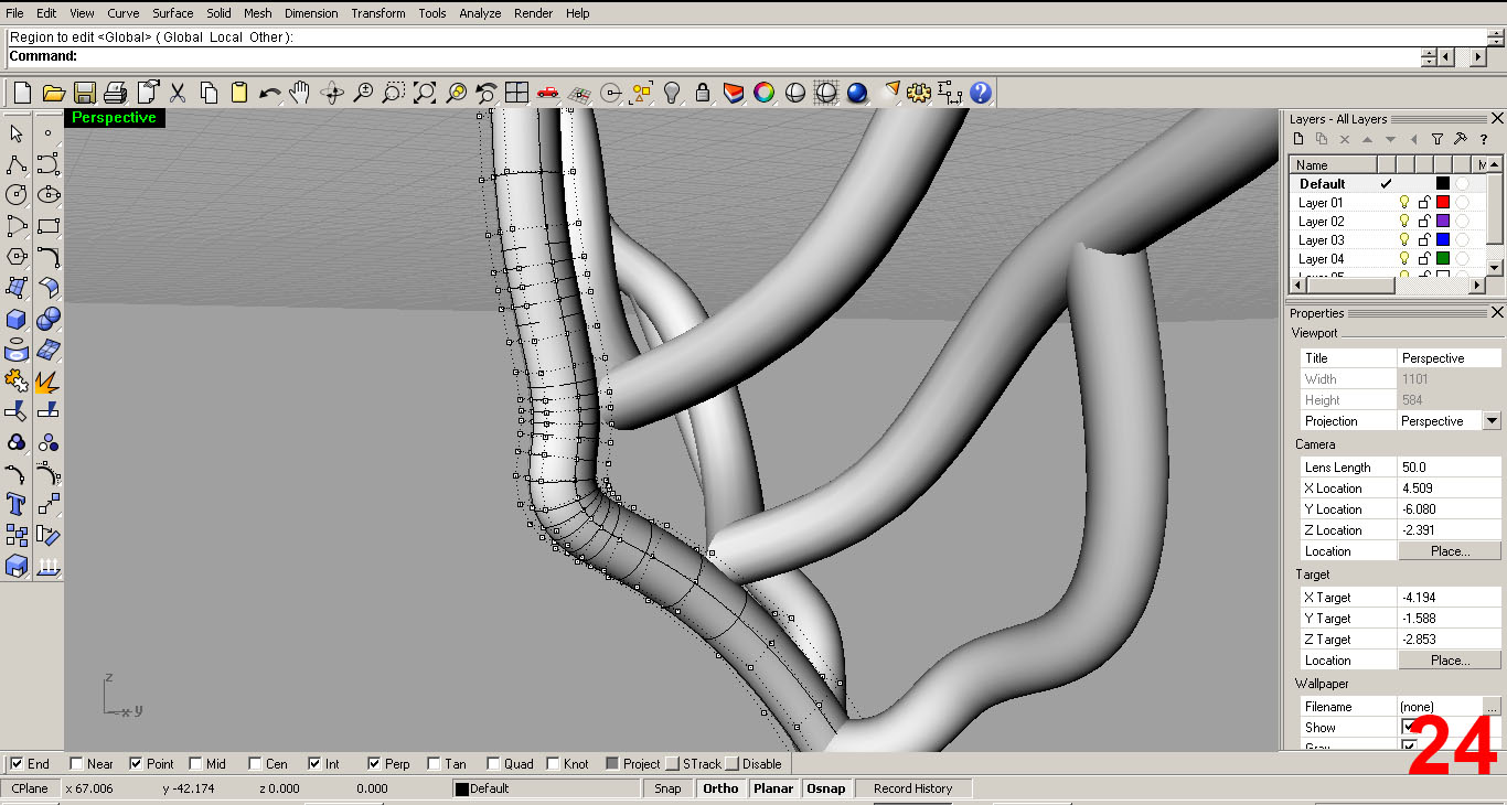
Now, hitting F10 brings up the control points, which can now be moved, scaled, and rotated. Now I can edit the surface into something more boney/organic. IMAGE 24
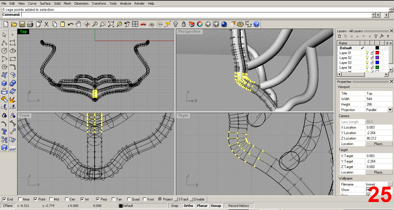
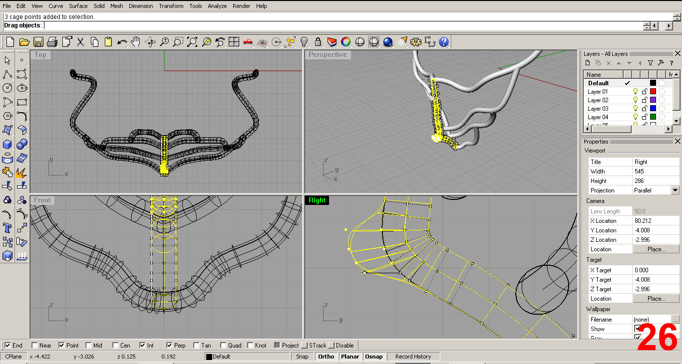
I select a group of points and then move them in the side viewport with ORTHO and PLANAR set to ON to create a bulge. IMAGES 25, 26
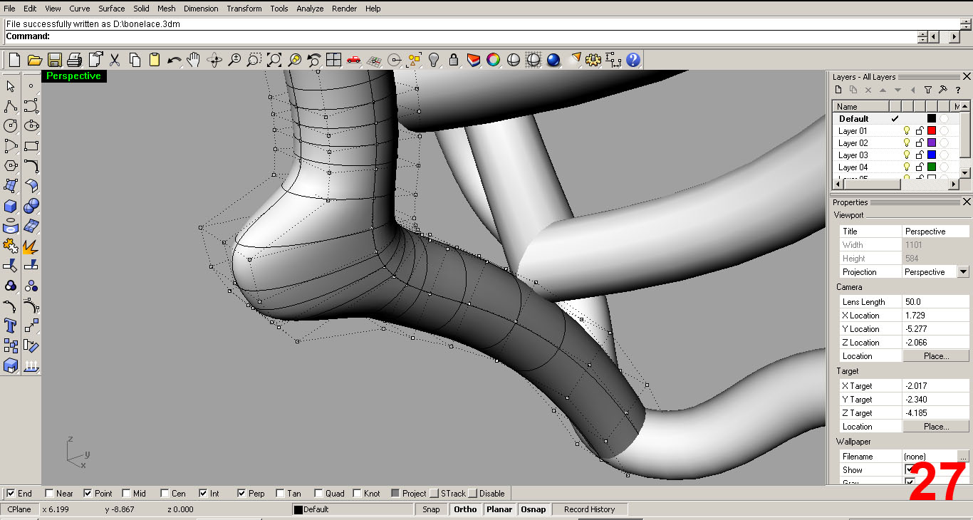
IMAGE 27 shows the move in the perspective port.
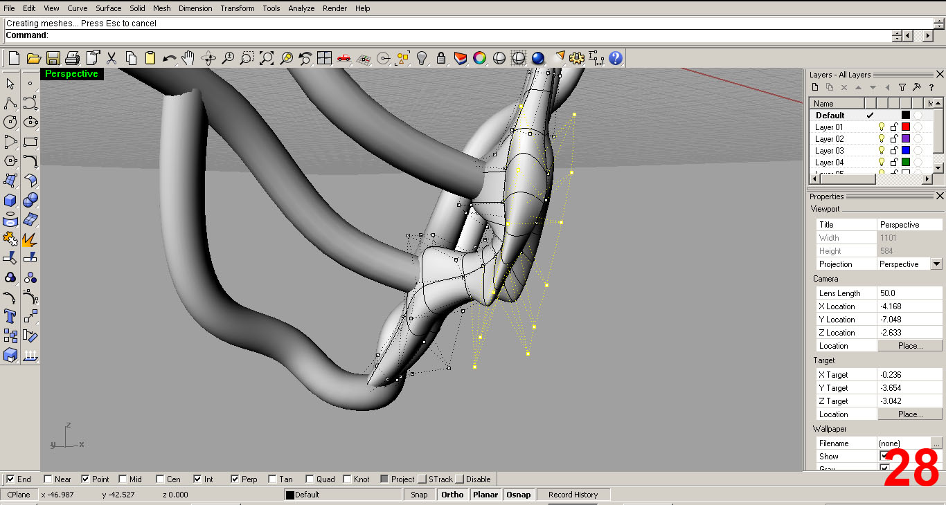
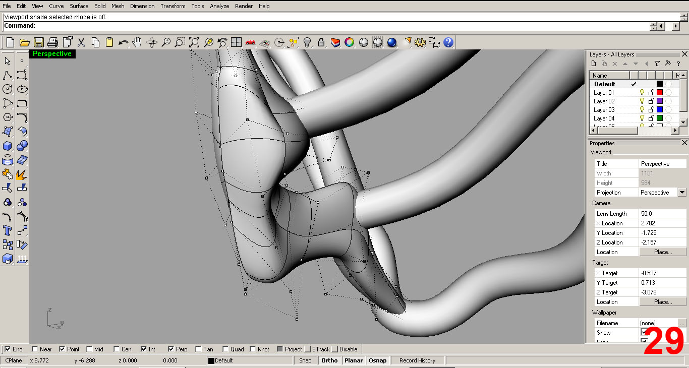
By further editing in all viewports which was achieved by moving, scaling, and rotating individual points, as well as groups of control points, I have refined the simple piped surface into a form that resembles something boney and vertebrae-like. IMAGES 28, 29
It took many trys and “undo” commands to get the surface to like this. Trial and error baby!
SHAPING THE RIBS
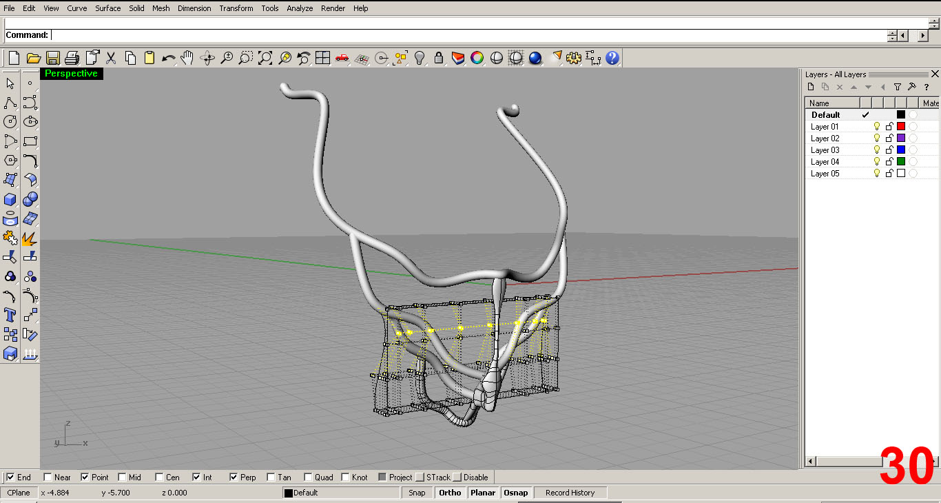
Zooming back now, I need to shape the lower “rib”. I did so a little differently than the center piece, or “vertebrae”. I still use the “cage edit” command, but instead of selecting the actual surface as the cage, I chose the bounding box option in the command line, setting up a cage/grid around the entire surface. I set the region to “global”. This brings the entire surface under the influence of a network of control points.
Using this network, I can select entire rows to move/scale at once, across the whole surface. This effects a much wider range than does the previous method used on the vertebrae piece. While editing in all ports, I make sure that the ends of the surface tuck into the rib above. IMAGE 30
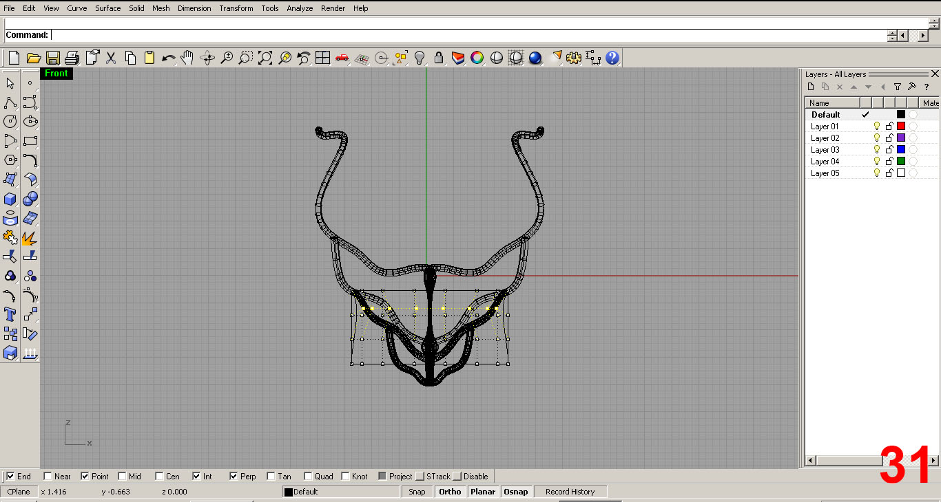
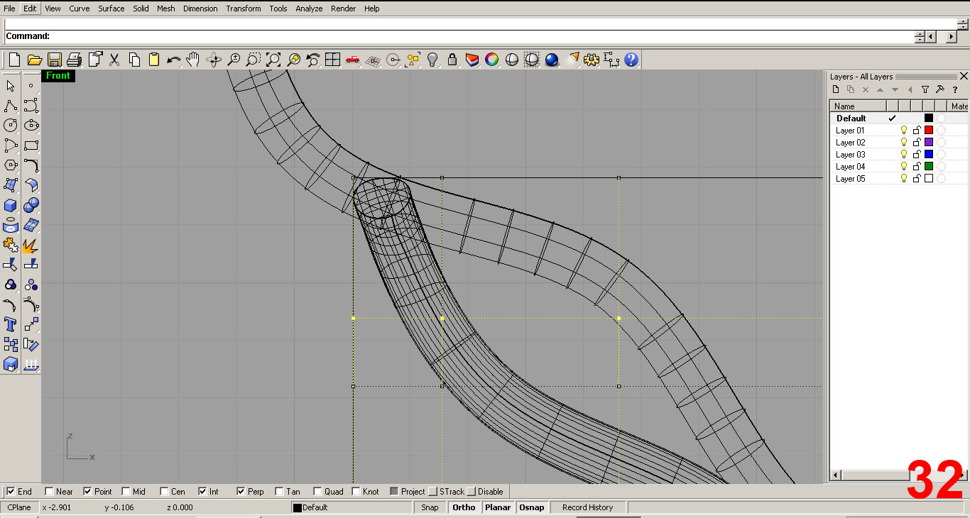
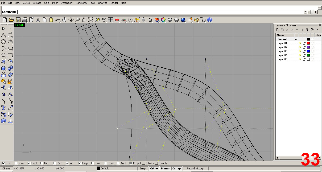
Next it is on to the second rib piece. Again, I used the cage/boundary box method and make sure that the ends tuck into the piece above. IMAGES 31, 32, 33
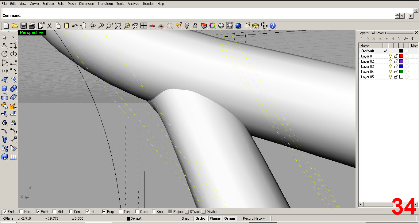
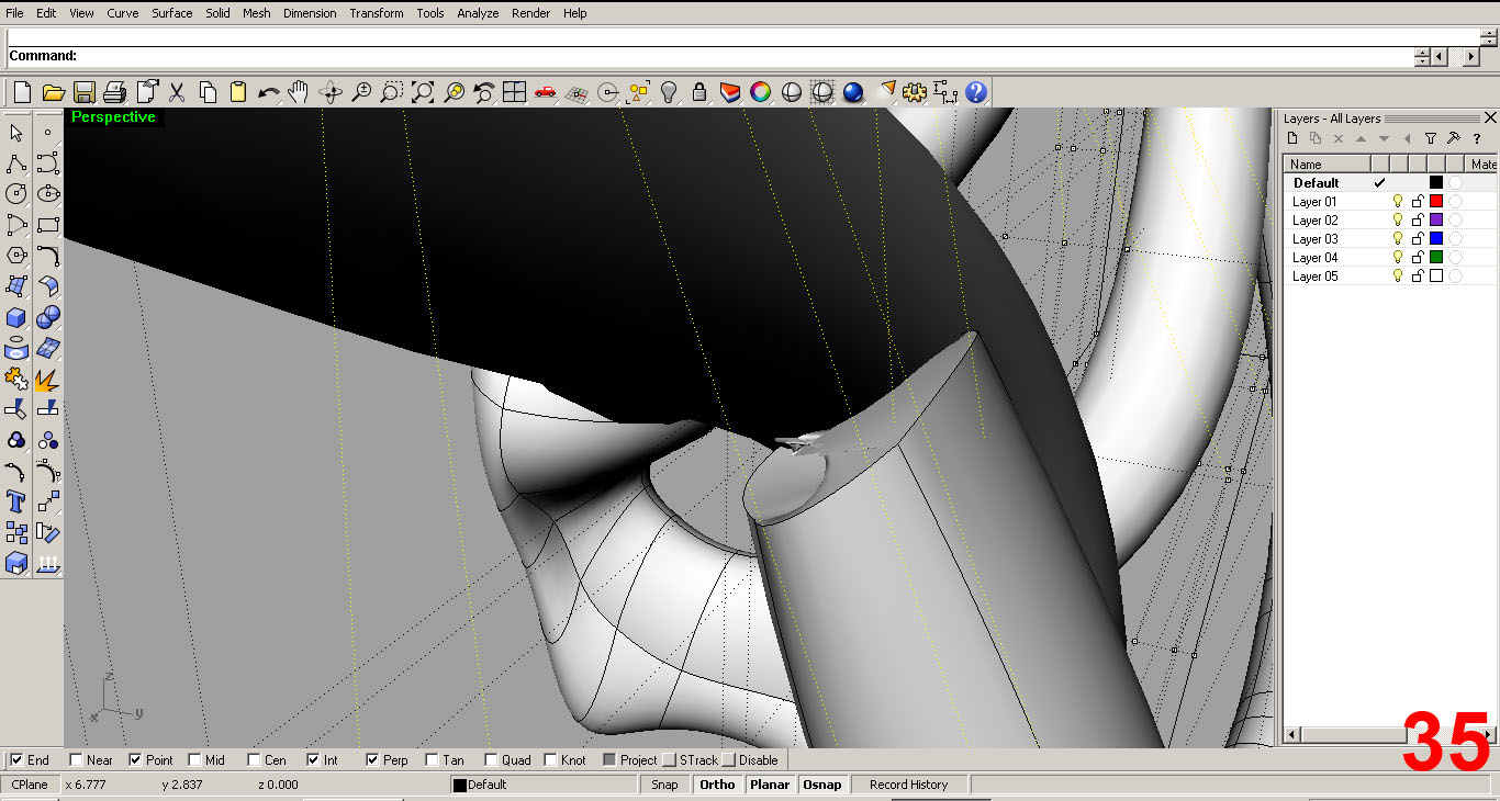
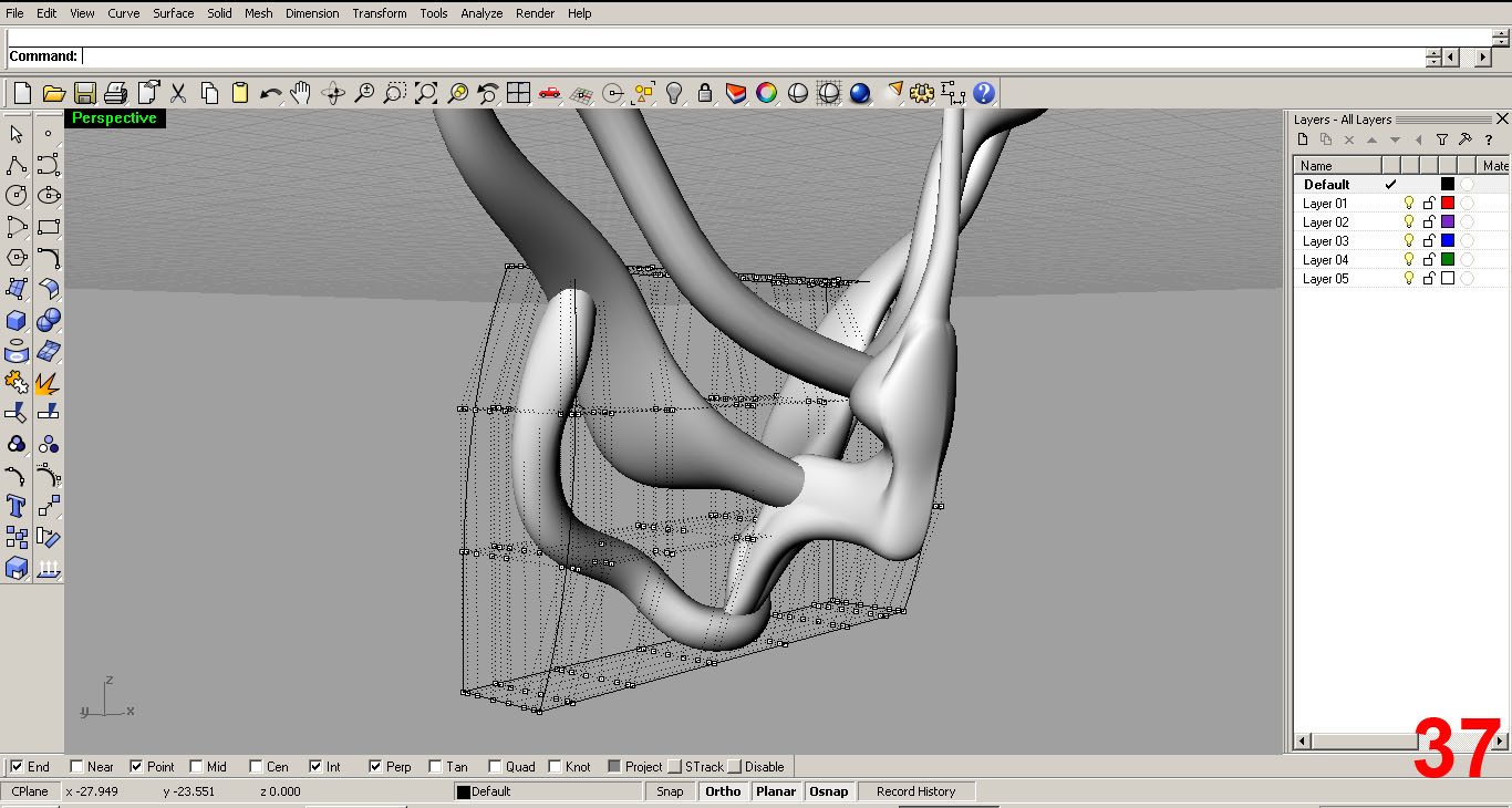
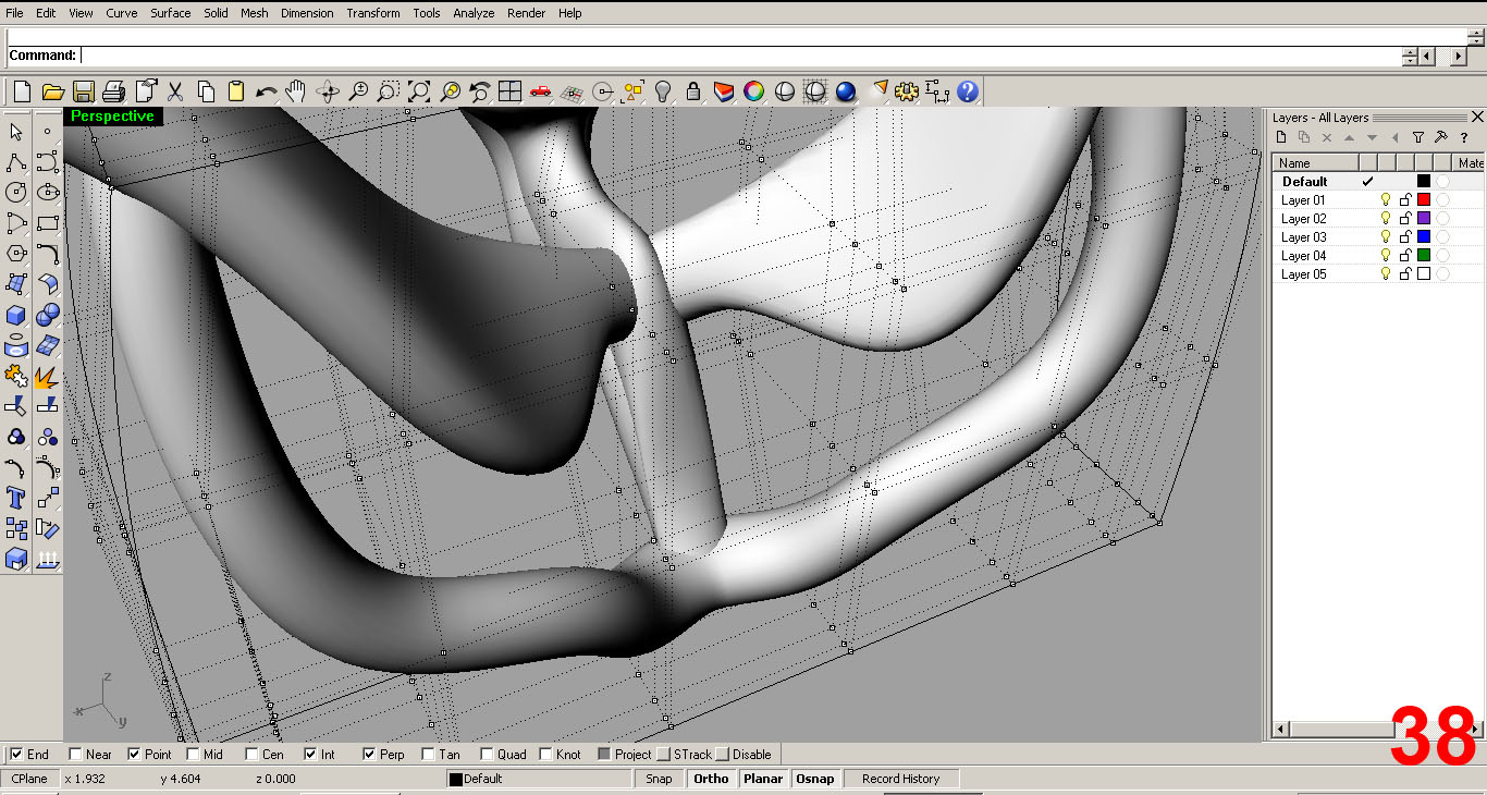
IMAGE 34 shows the rendered view of nice smooth joint. Or so it seems...IMAGE 35 tells a different story. You can see the end is all gnarled and ugly. This will be taken care of later. For now, I just need to make sure that the end goes inside of the piece above it. I will union these later to make a solid piece and the gnarled end will be cut off.
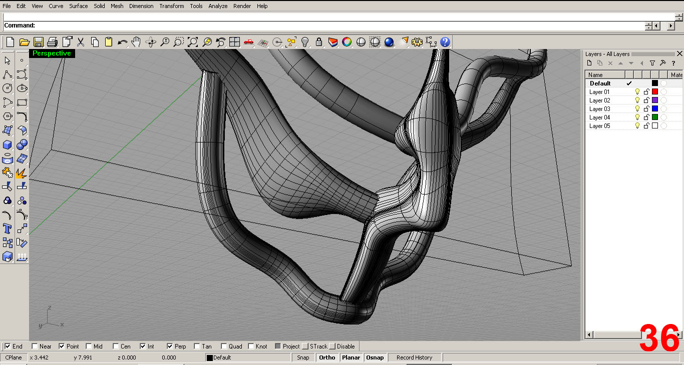
IMAGES 35, 36, 27, 38 further depict the editing process. I refine the ribs further, making sure the ends are tucked.
SHAPING THE COLLAR
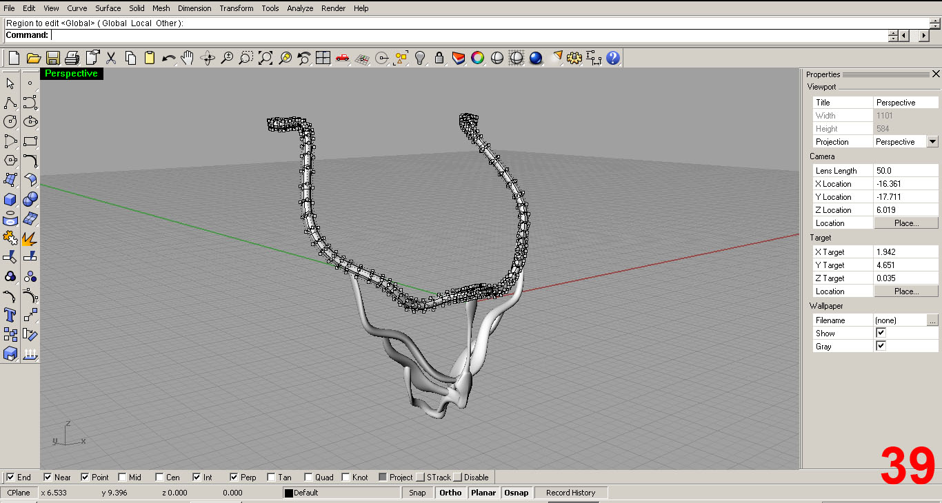
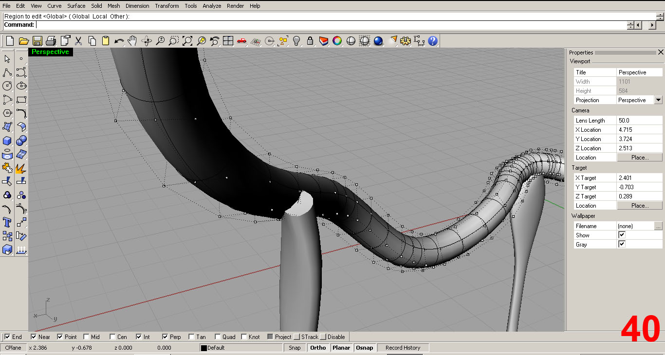
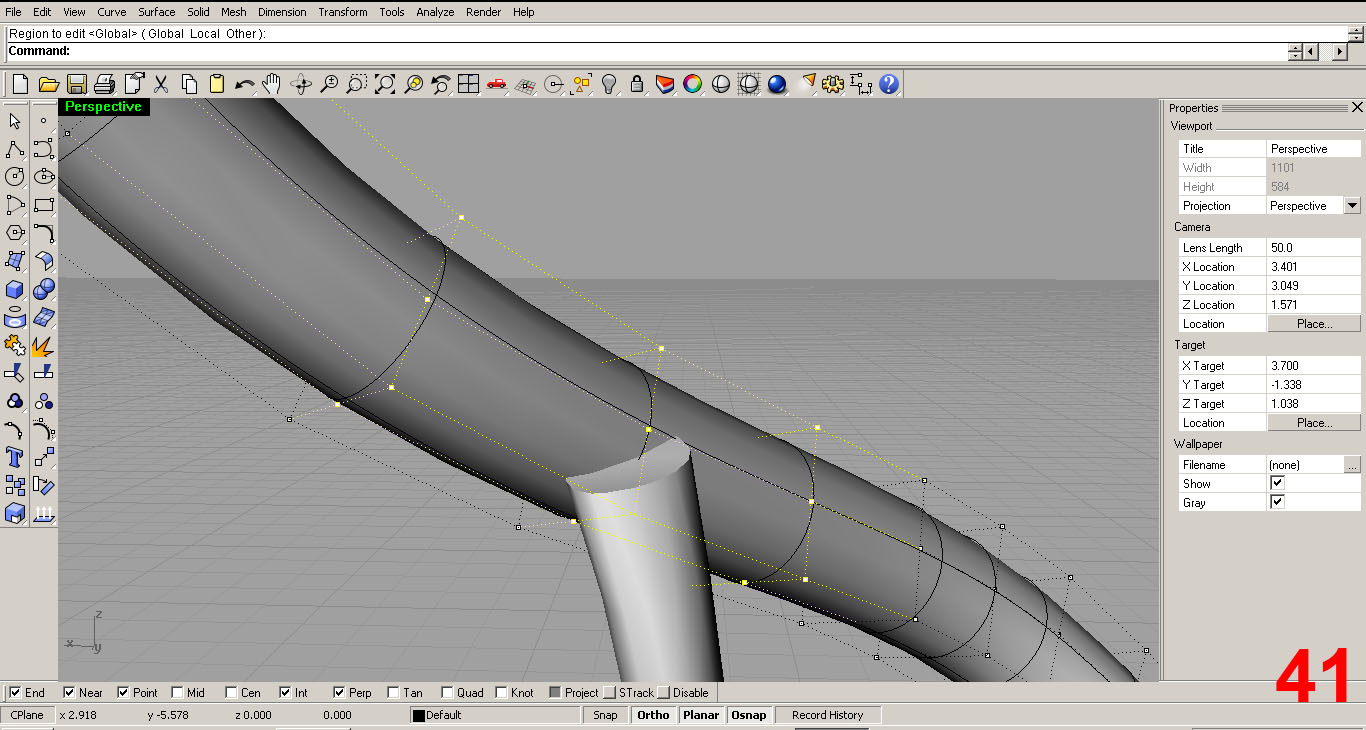
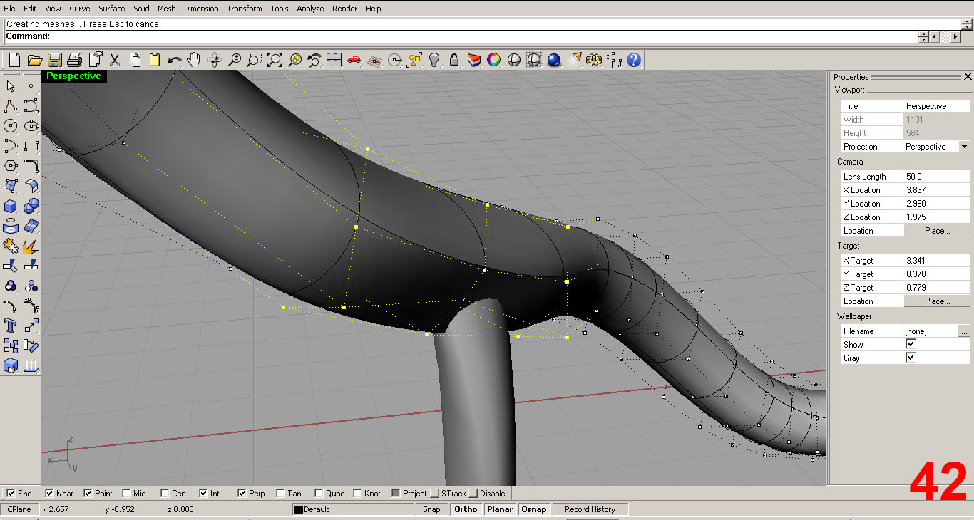
You can see in IMAGE 40 that I need to adjust the band so that it fits nicely over the rib piece below it. I select some control points in the area I want to edit and simply move them over the end of the rib. IMAGES 41, 42
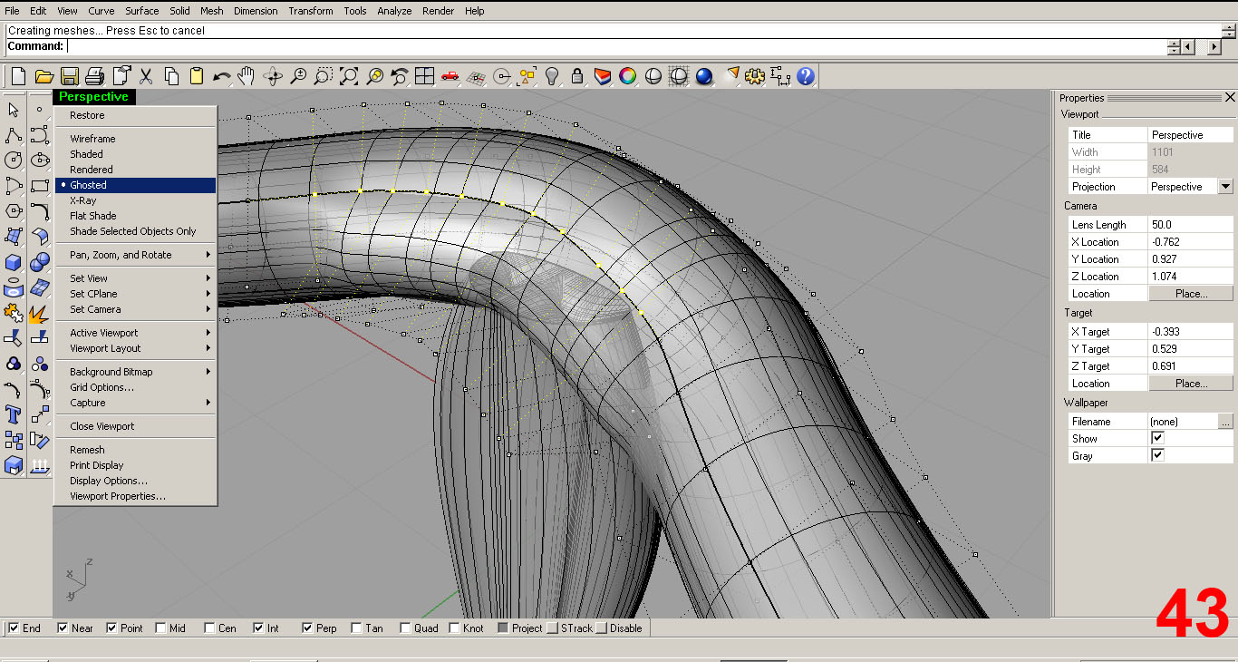
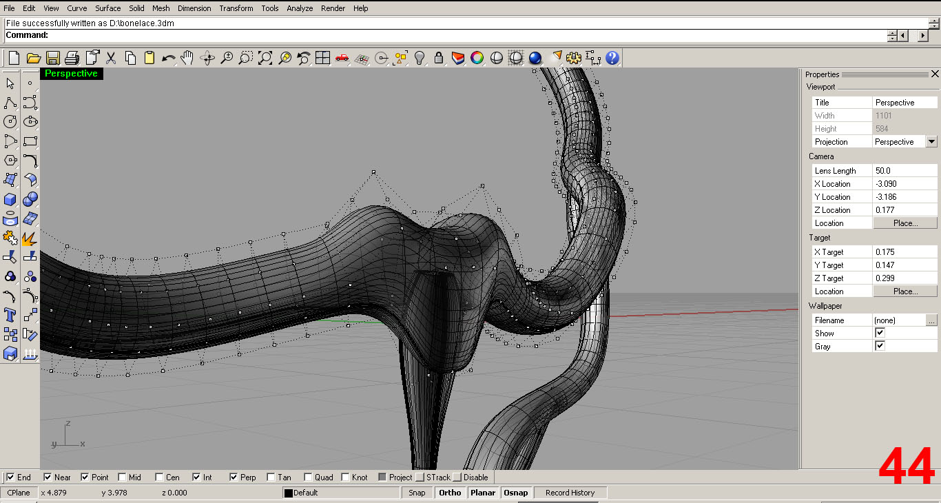
Next I edit the region of the band that rests over the central spine. IMAGES 43, 44. Note that in IMAGE 43, I switched the viewport to ghosted to get a better feel for the intersection of the two pieces.
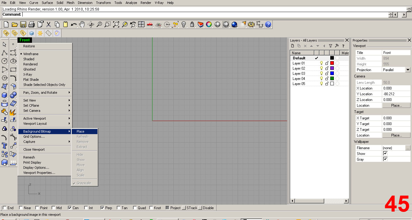
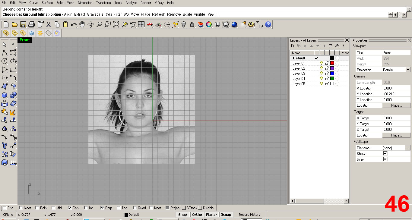
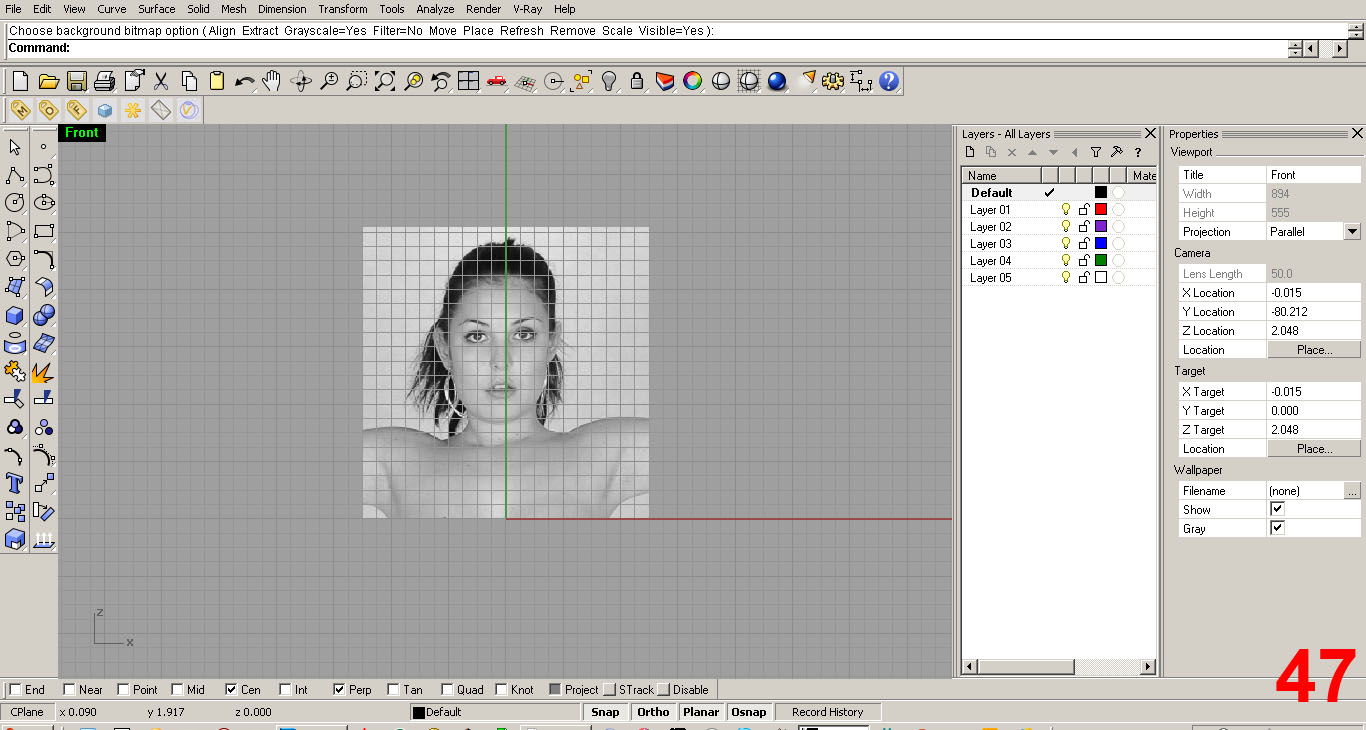
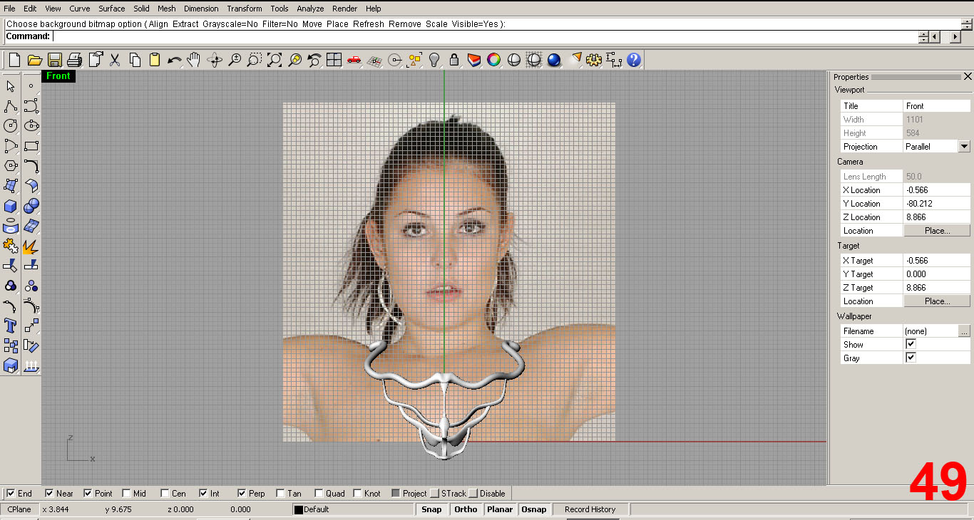
At this point I want to check and make sure that my proportions are going to work and I haven't gotten out of control with my dimensions. I do so by adding a “background bitmap” of a female to use as a reference. IMAGES 45, 46, 47
I got the images online using Google image search. You'll need to create the background bitmap in each viewport, as the bitmap is viewport specific. Placing an image in the Front Viewport only shows an image in that viewport. Naturally, you'll want to chose an appropriate side of your human for each viewport.
Once placed, you can move and scale the bitmap image to get the correct size. I drew a line 5” long (which is about the width of female neck) and scaled the image (referencing the girl's neck) to that line. I moved the image to center and positioned the model in all viewports to match how it will be worn.
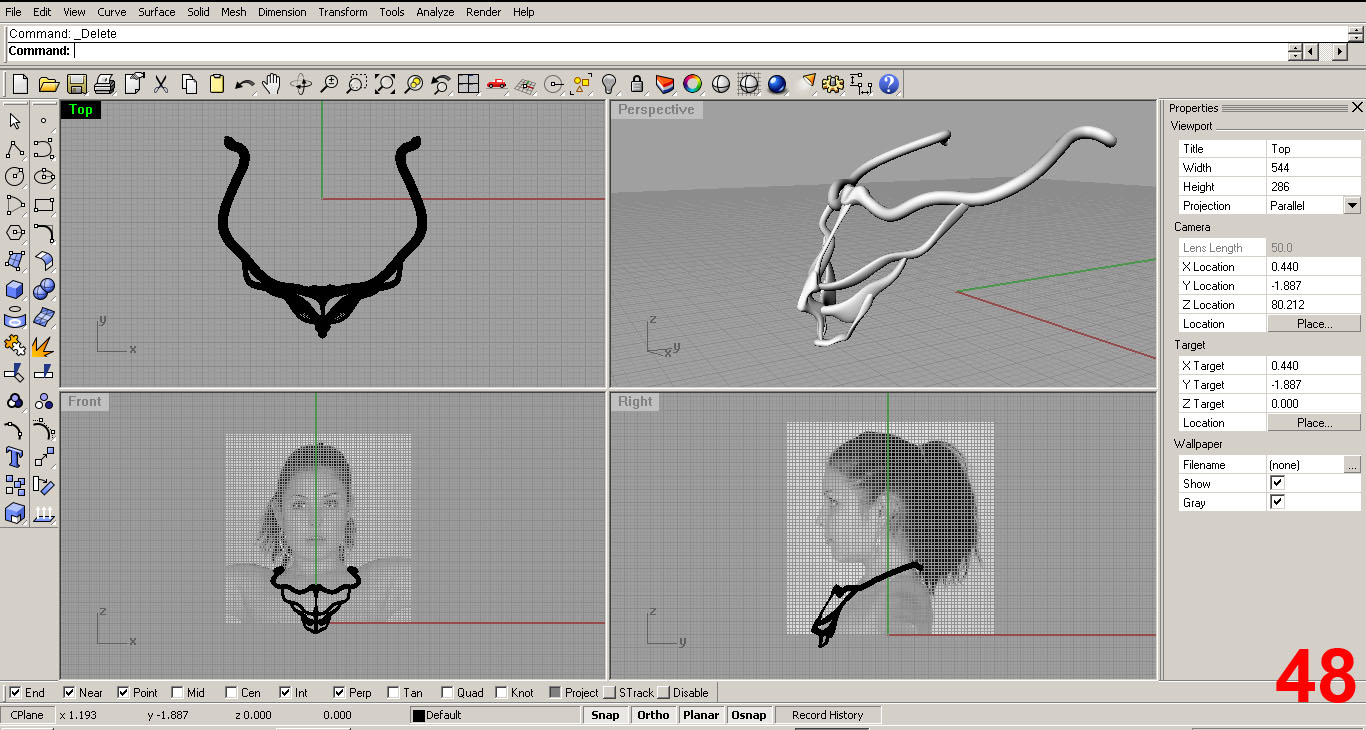
In IMAGES 48, 49 you see the bitmaps added, scaled, and positioned properly with the model placed accordingly.
FURTHER REFINING THE MODEL
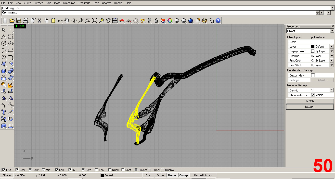
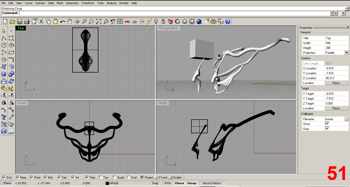
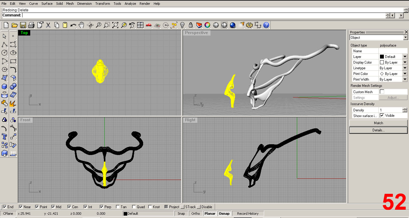
Now, I will sculpt this “clone” a bit differently than the original component. First, I performed a “Boolean Subtraction” operation on the clone to remove the upper portion of the piece. This works by taking the mass of one object and using it to cut another object. Note: Rhino has a built in command help with animated examples of how the tool works. Make use of it, it is helpful and a really cool feature.
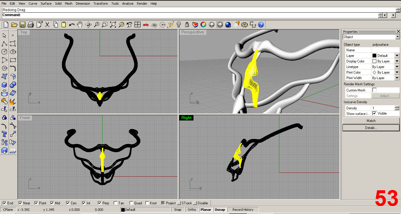
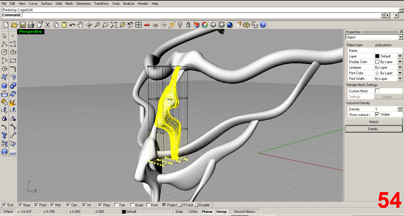
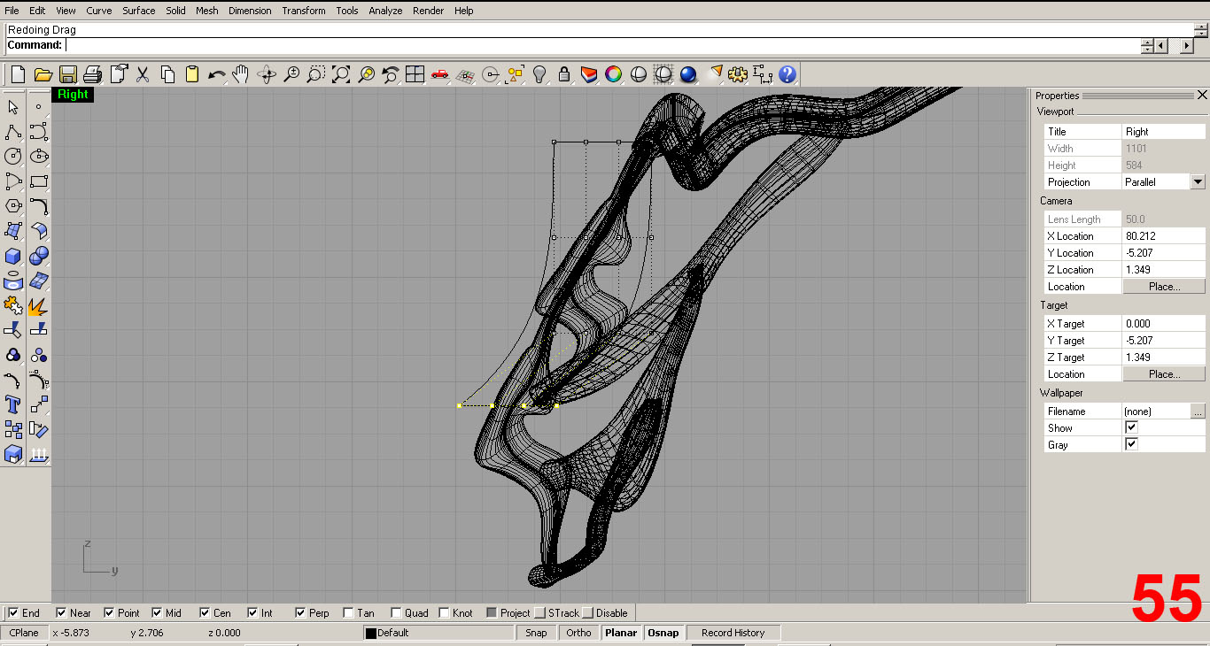
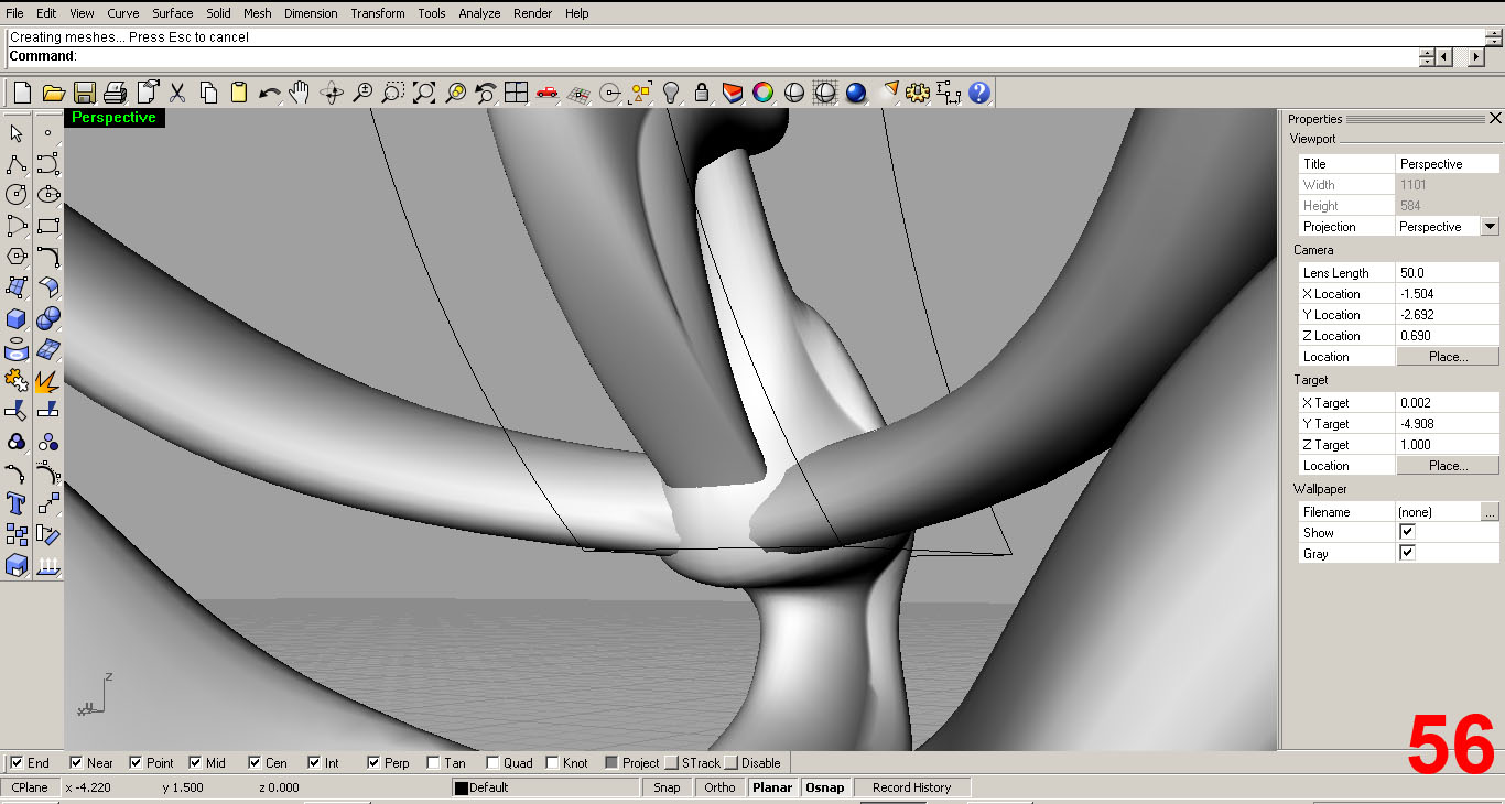
Next I positioned the clone where I want it to go. Once again using cage edit, I tweak the form. IMAGES 51, 52, 53, 54, 55, 56.
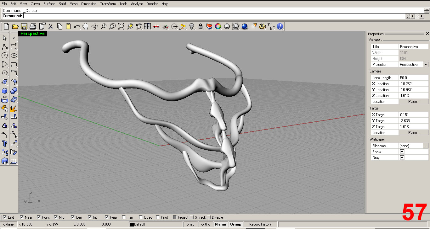
IMAGE 57 Shows the final result of this sculpting, with context.
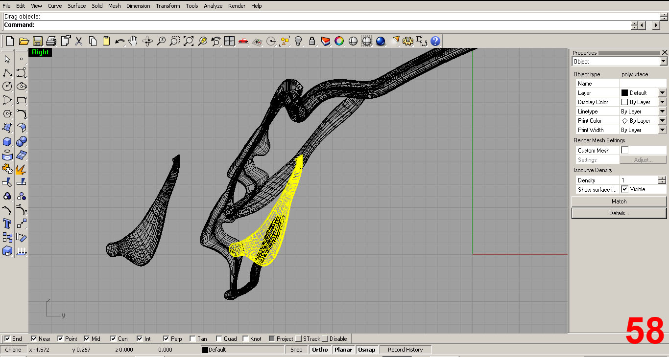
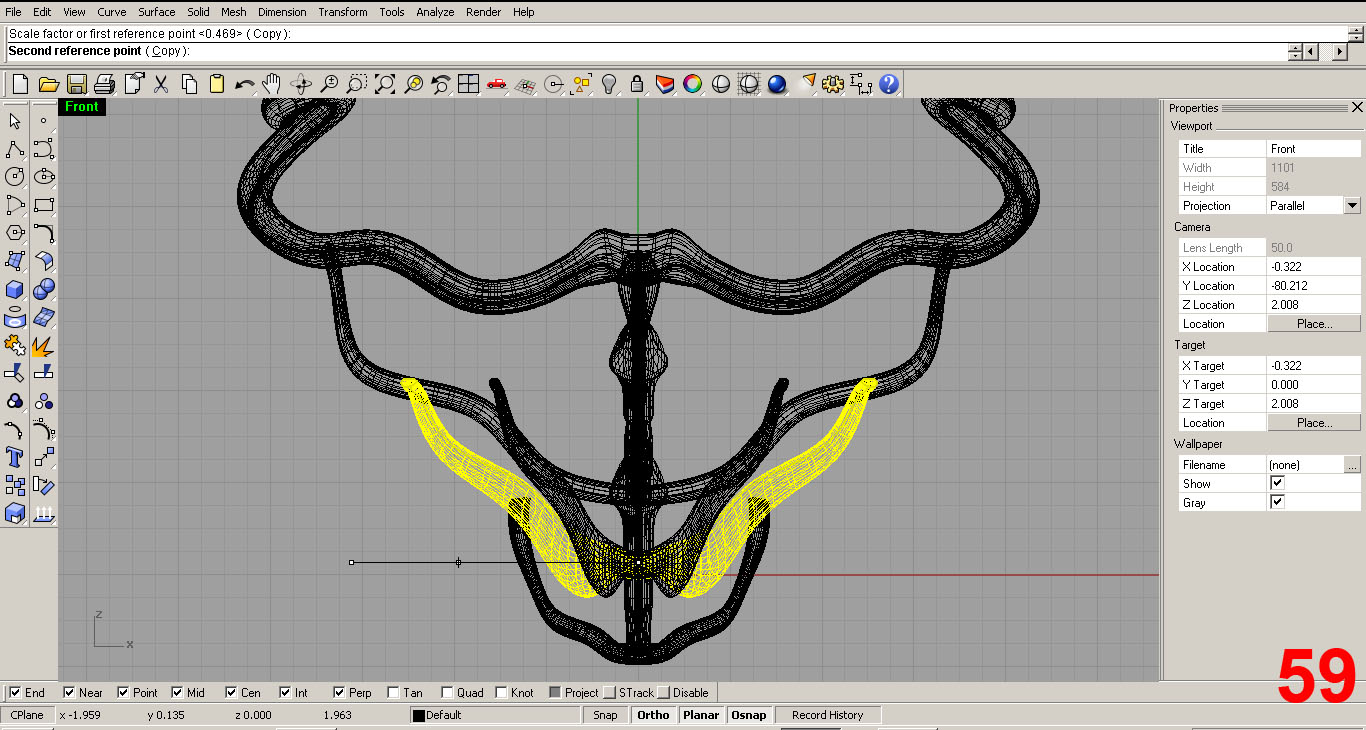
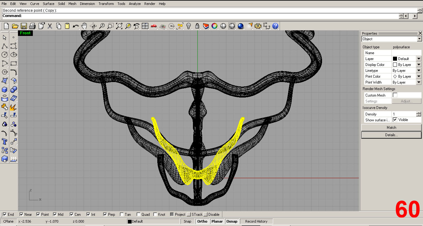
I now add another rib piece by copying an existing component. I edit this piece by using the “scale” command. IMAGES 58, 59, 60
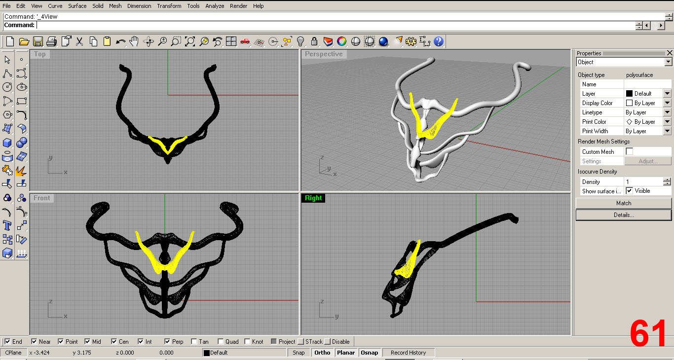
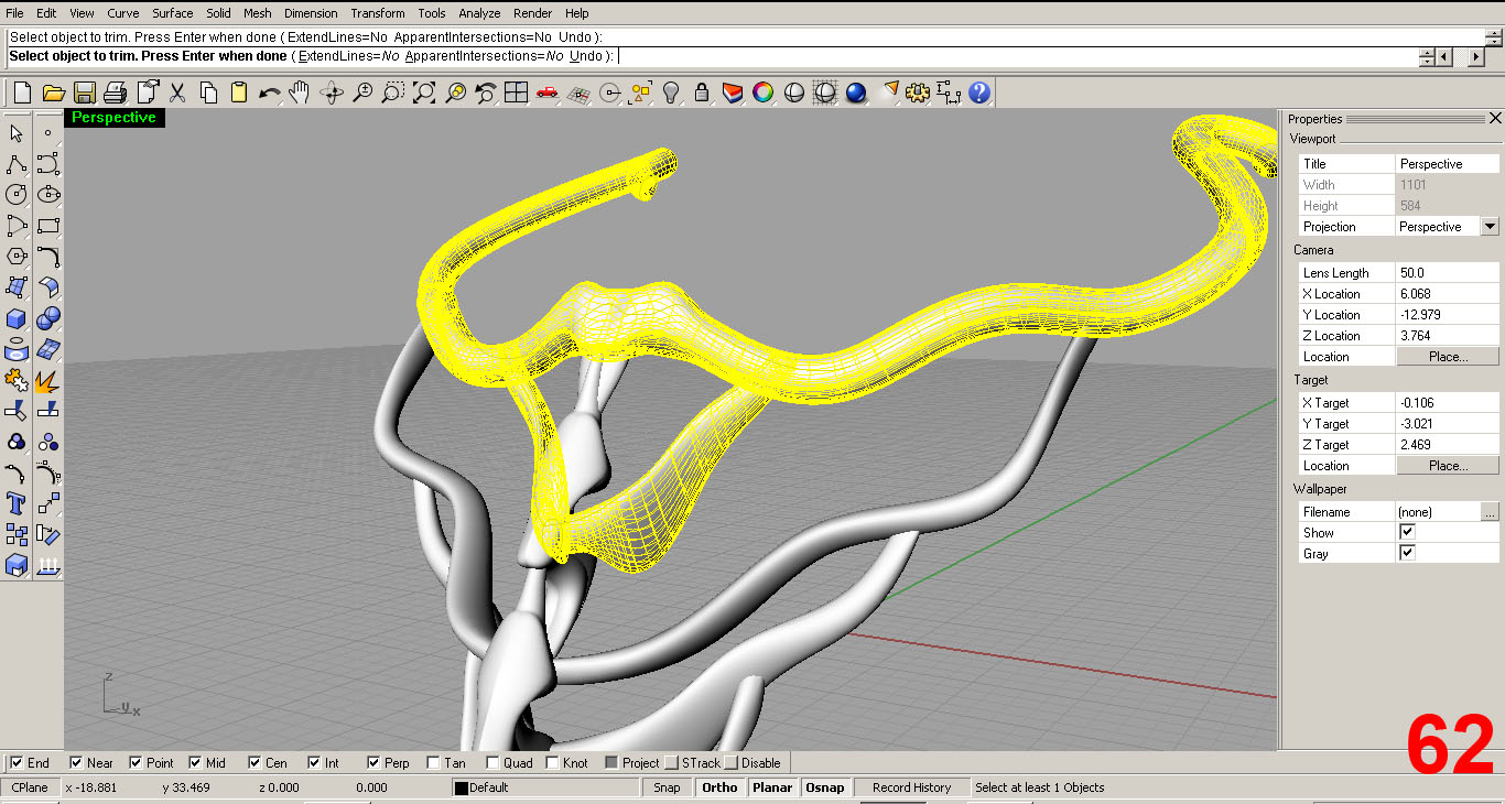
Satisfied with the initial form, I position the piece and use the “trim” command to remove the excess part of the rib that sticks out past the collar. IMAGES 61, 62
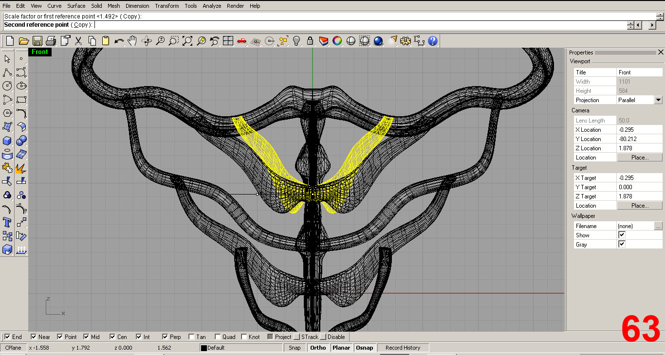
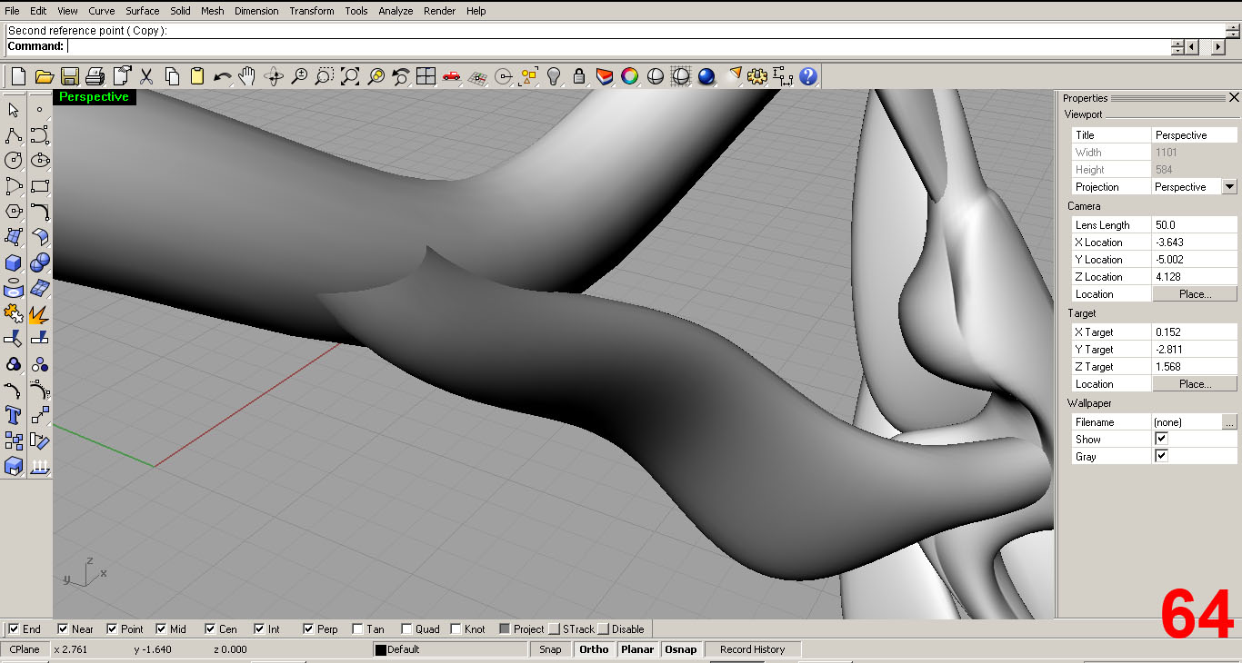
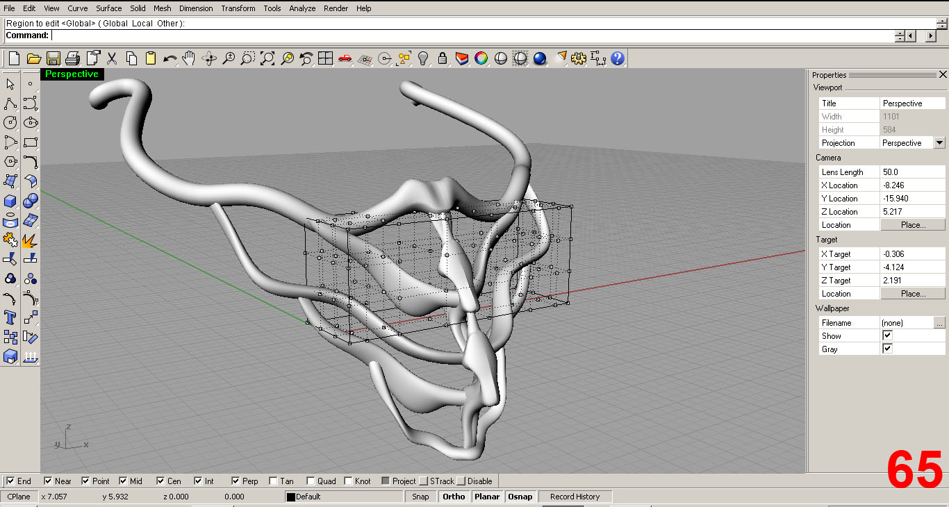
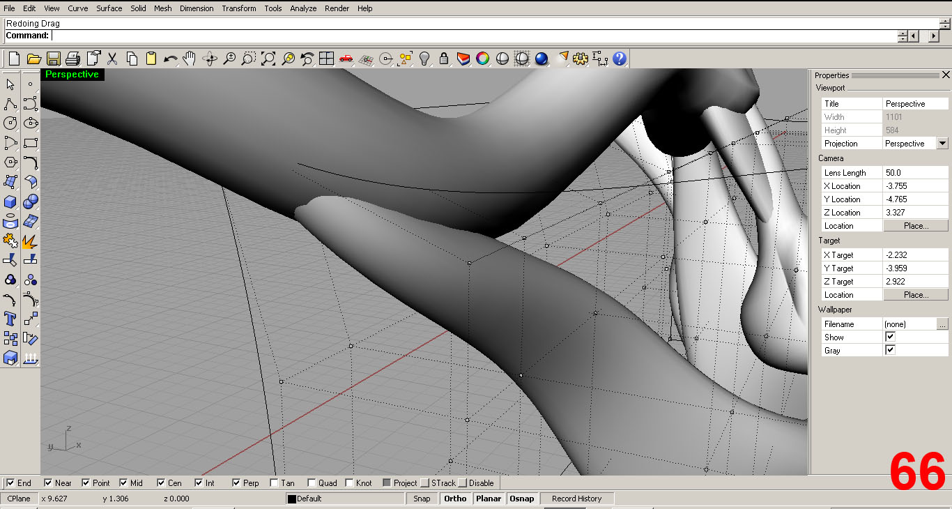
I further edit using scale, cage edit, and move tools. IMAGES 63, 64, 65, 66.
In IMAGE 64 you can see the parts are not lined up well, so I correct this using cage edit, moving the bounding box control points as needed.
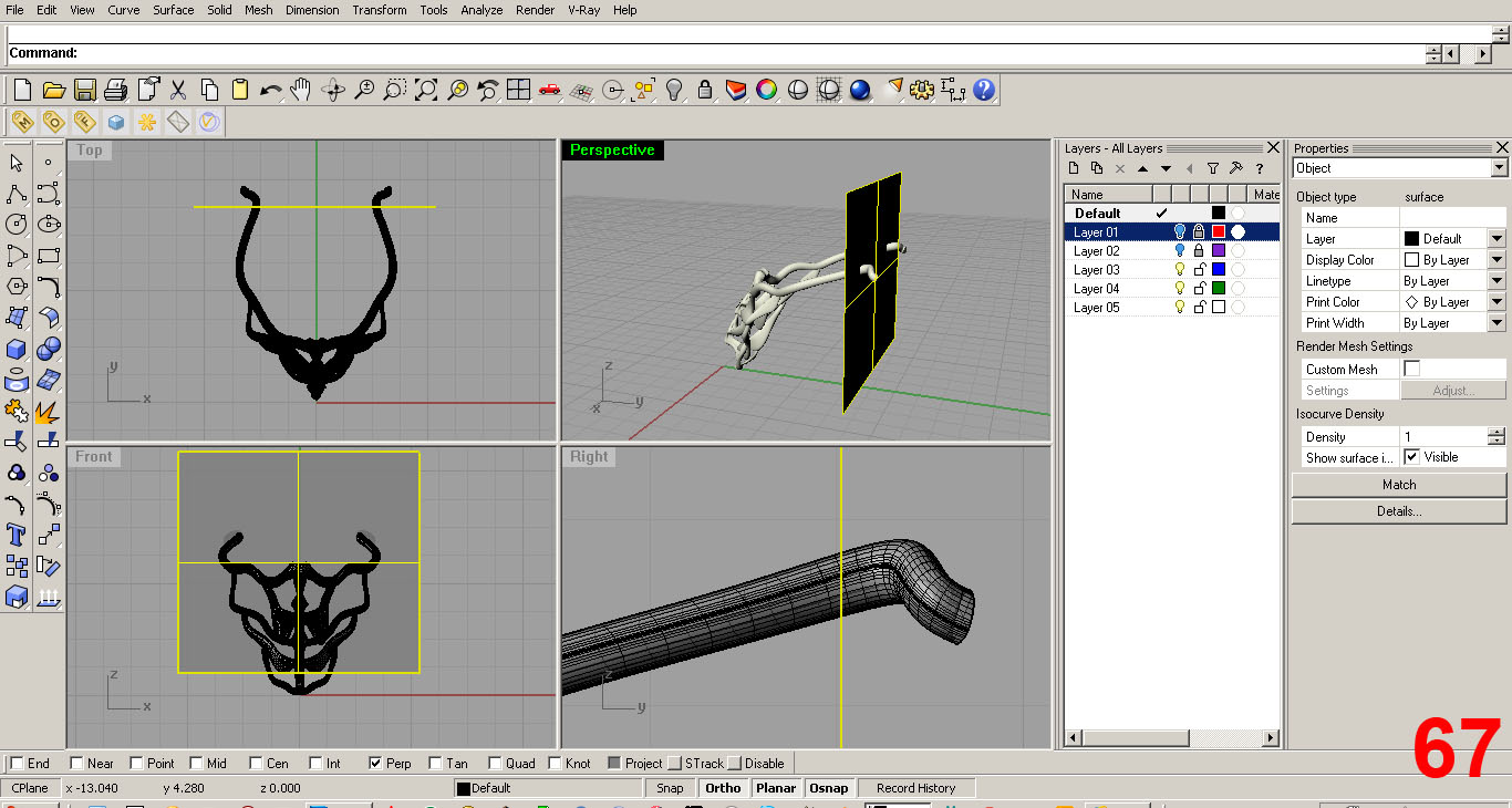
At this point, my major moves were complete. However, after looking the model over I decided that I did not care for the ends of the collar piece. The ends will be behind the neck and this is where a chord/string will secure to the physical model in order to hold the piece on the body. The curved form at these ends just didn't seem to make sense so I decided to simplify the ends.
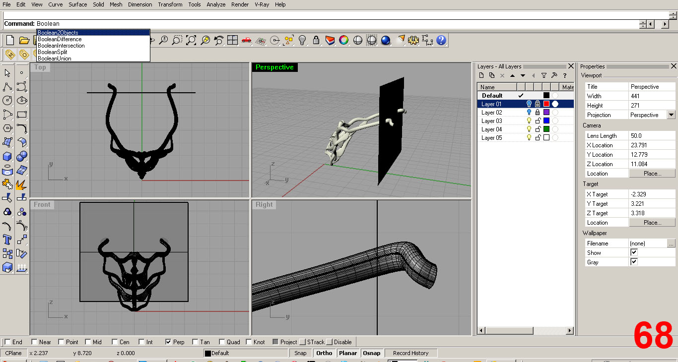
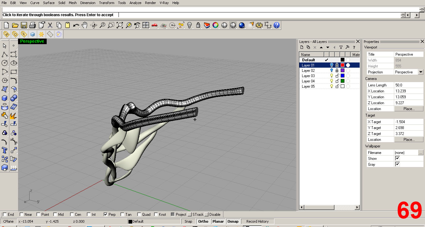
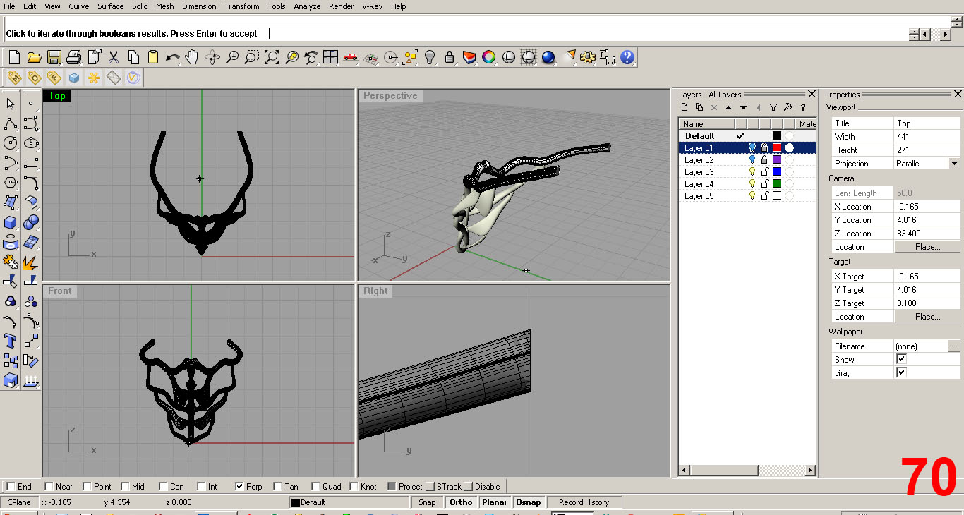
I created a plane that I can use as a cut object and “Boolean Subtract” the ends. IMAGES 67, 68, 69, 70
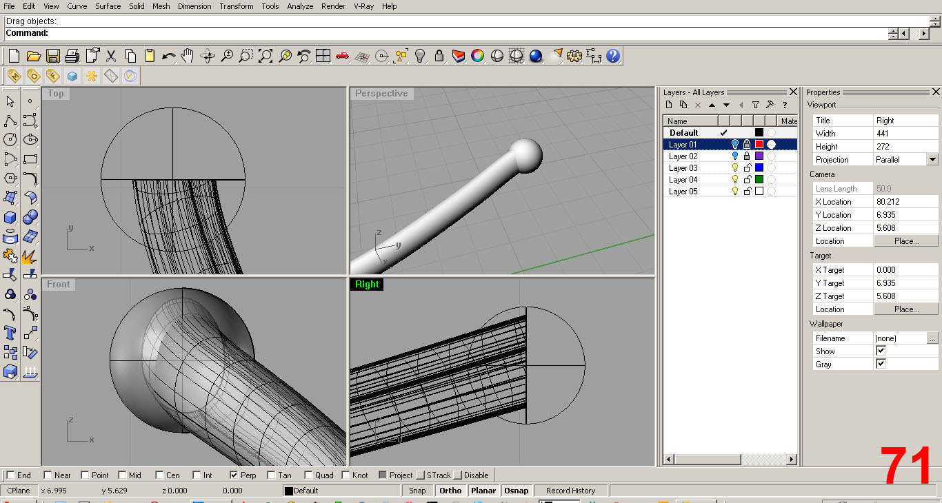
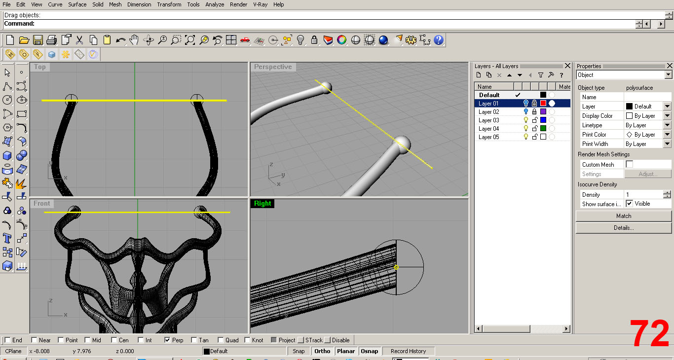
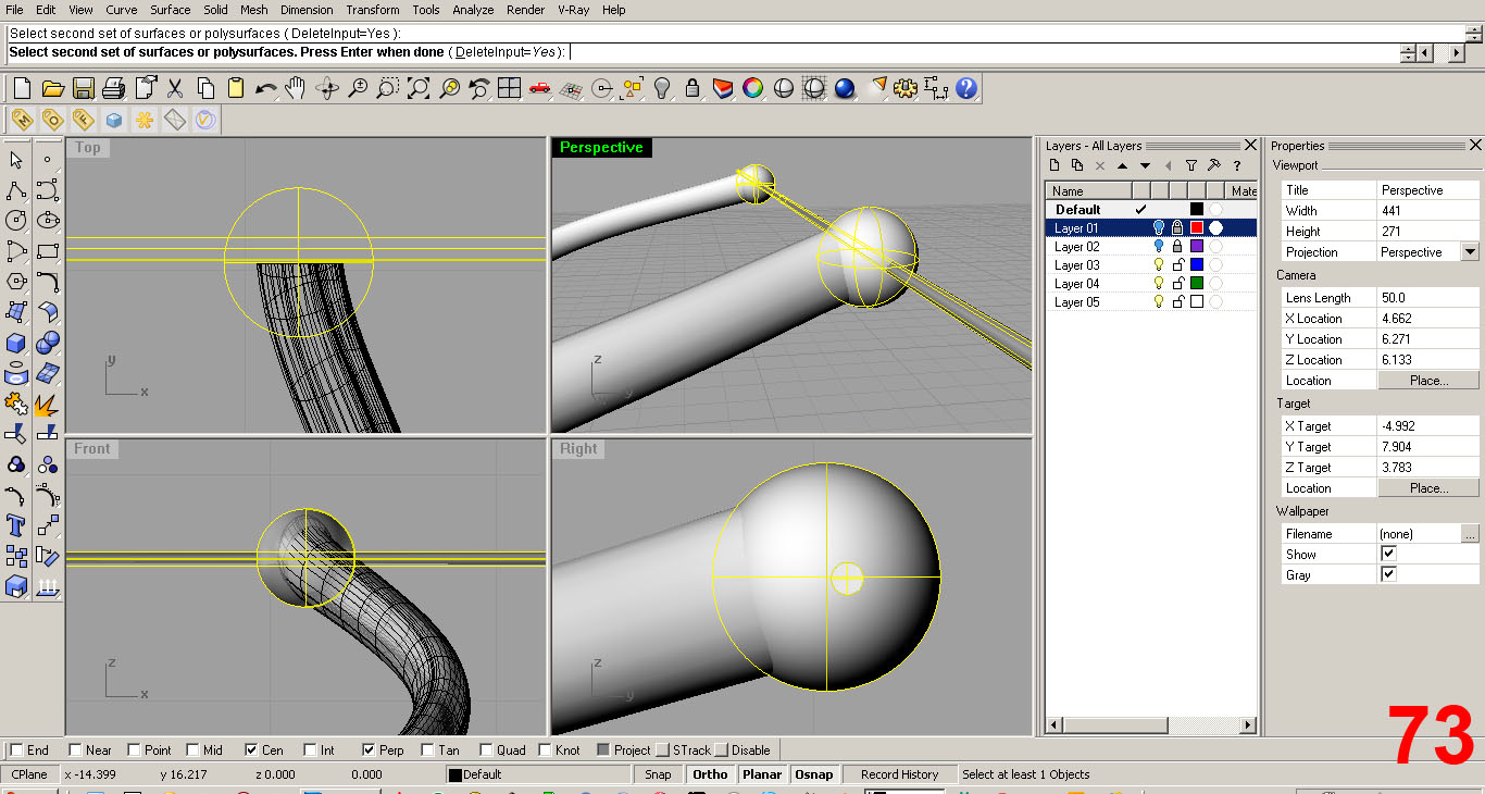
Two small spheres were added at the ends and I “Boolean Subtract” a 1/16” diameter cylinder to create small 1/16” diameter holes in each sphere. IMAGES 71, 72, 73
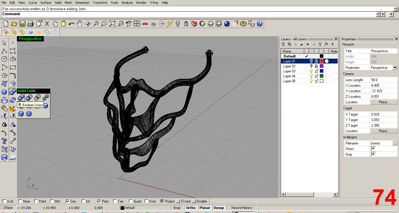
At last the pieces are ready to be joined into a solid “watertight” model, or “Closed Polysurfce”.
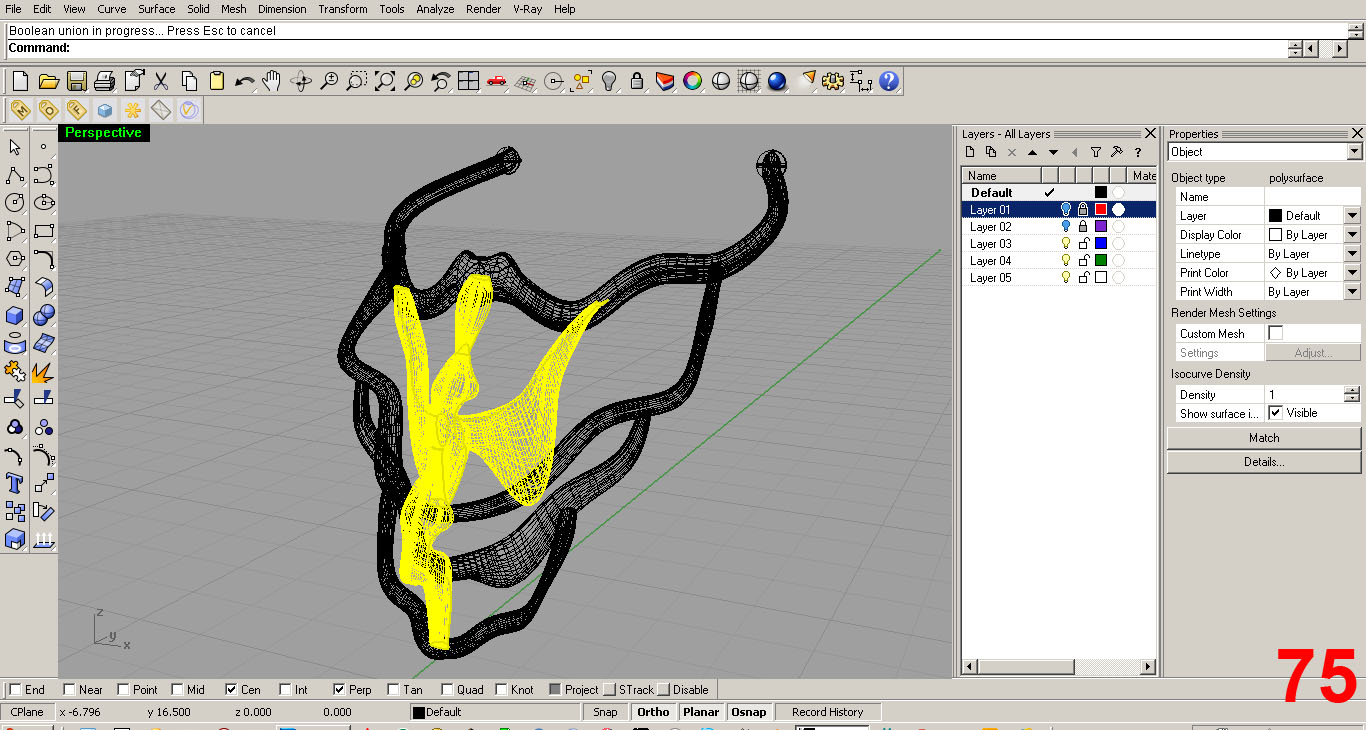
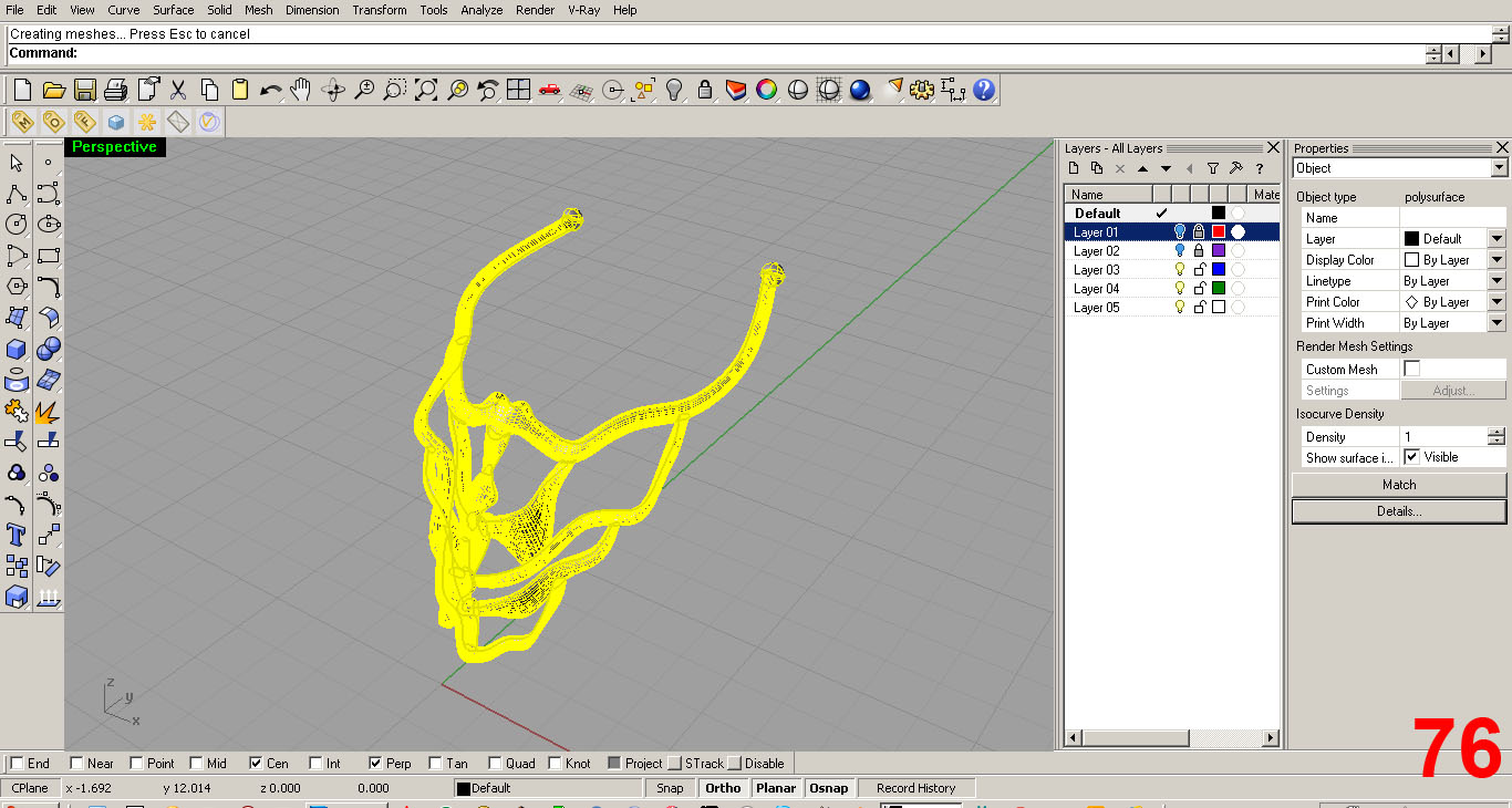
Using “Boolean Union” I go piece by piece, fusing one component to the other until I have a singular piece. Once these operations are complete I can not edit individual pieces. IMAGES 74, 75, 76
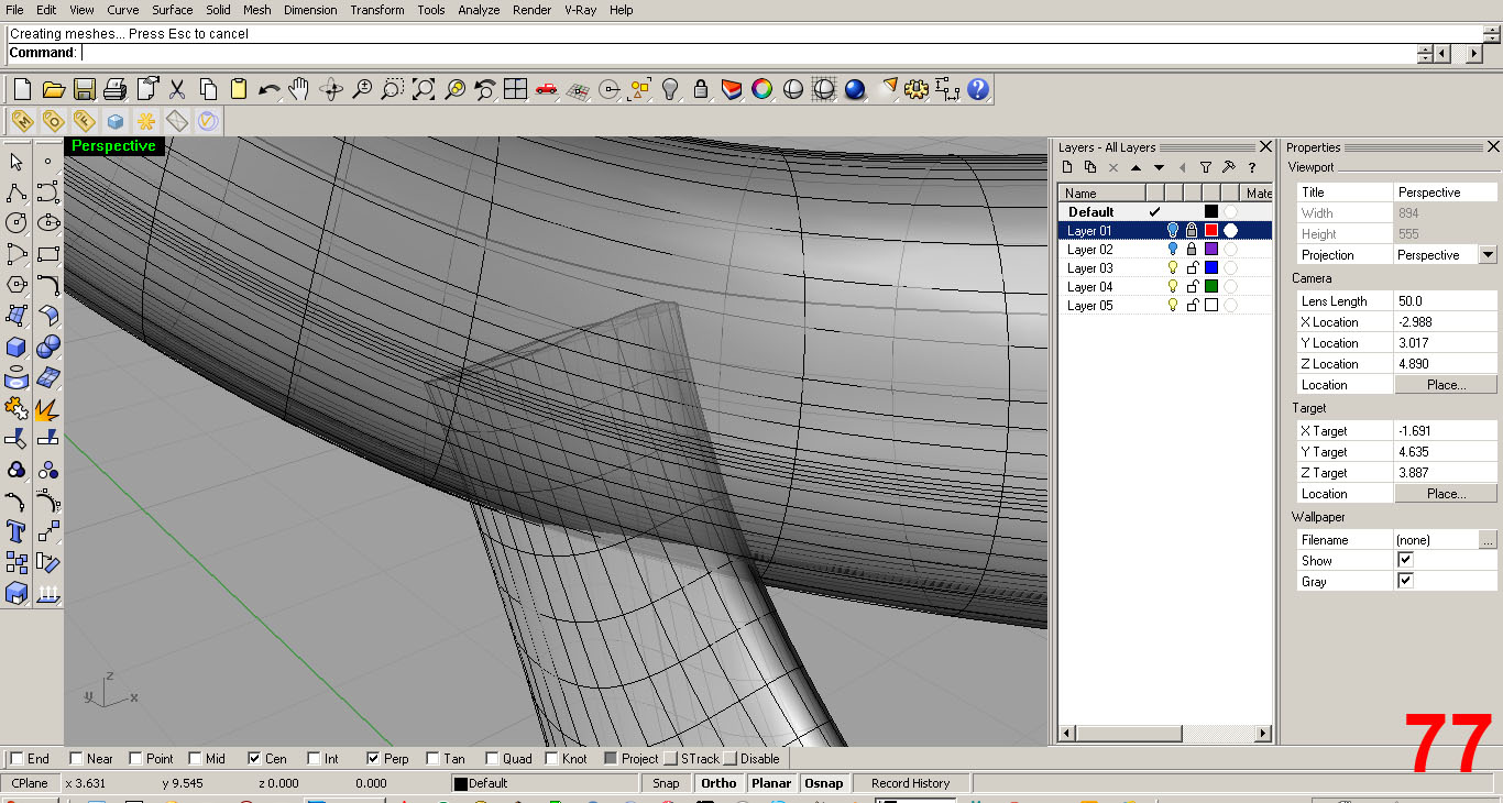
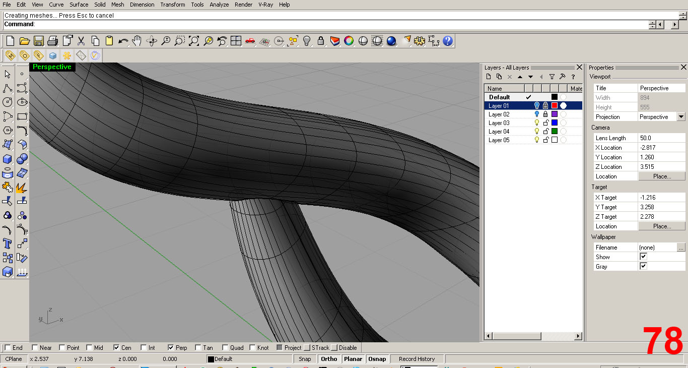
Once two pieces are fused with Boolean Union, the portion of a component that is inside another goes away, creating a nice clean joint/union. You may recall the comment I made about ugly looking ends. See IMAGES 77, 78
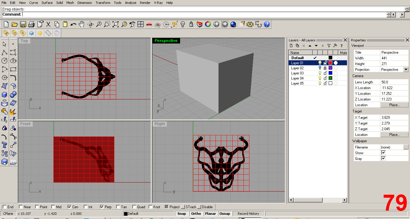
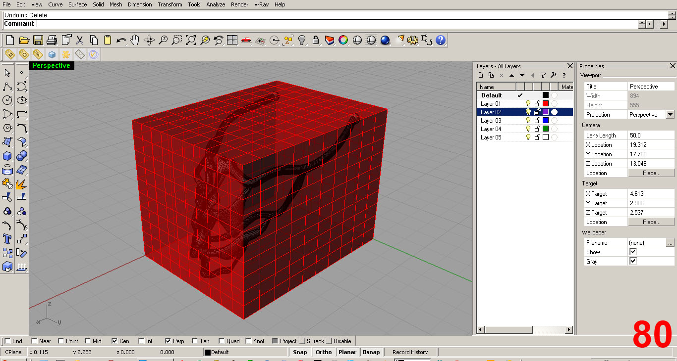
To position the model and double check that it will fit in the printer's boundary, I created a cube with the printer's boundary dimensions on a separate red layer for clarity. The printer I am renting for this project has an 8” x 6” base and a 6” height limit. Thus, my box is 8x6x6. IMAGES 79, 80
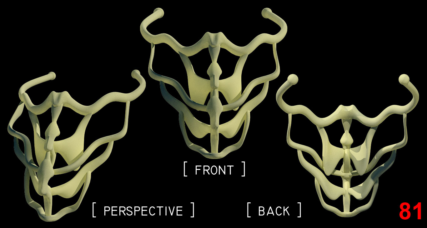
I used V-Ray to render the final model using a nylon texture to simulate the ABS plastic that the physical model will be constructed out of. IMAGE 81
CREATING THE .stl FILE AND PRINTING
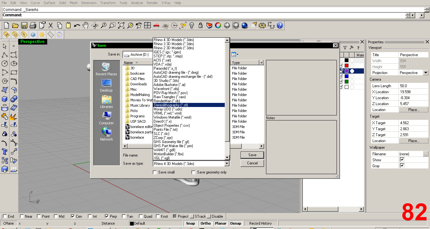

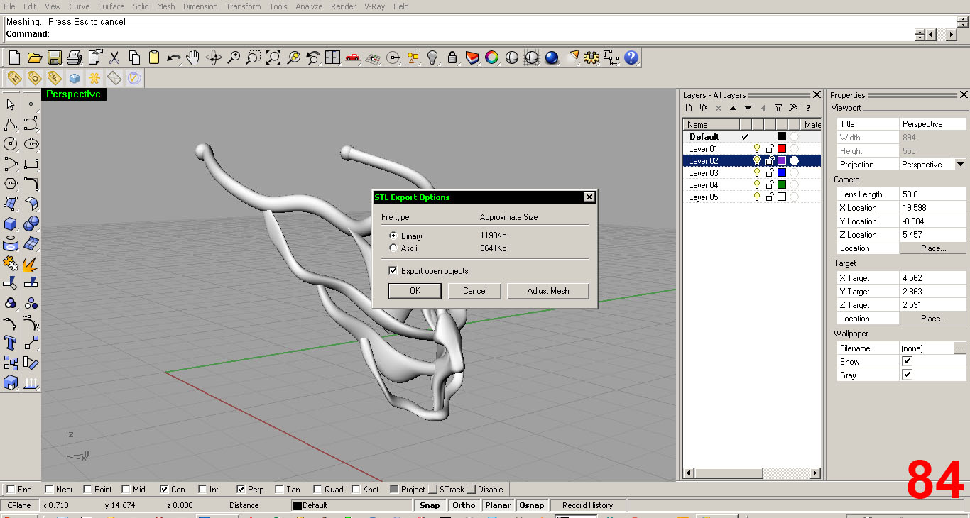
IMAGES 82, 83, 84 show the settings.
Follow the link below to get Rhino's advice on solid surfaces. The model MUST BE A CLOSED SOLID or “CLSOED POLYSURFACE.”
http://wiki.mcneel.com/rhino/faqclosedsolids
I checked the file after reading this webpage and all looked good. I open up the printer's software, open my “.stl” file, hit print, and it's off!
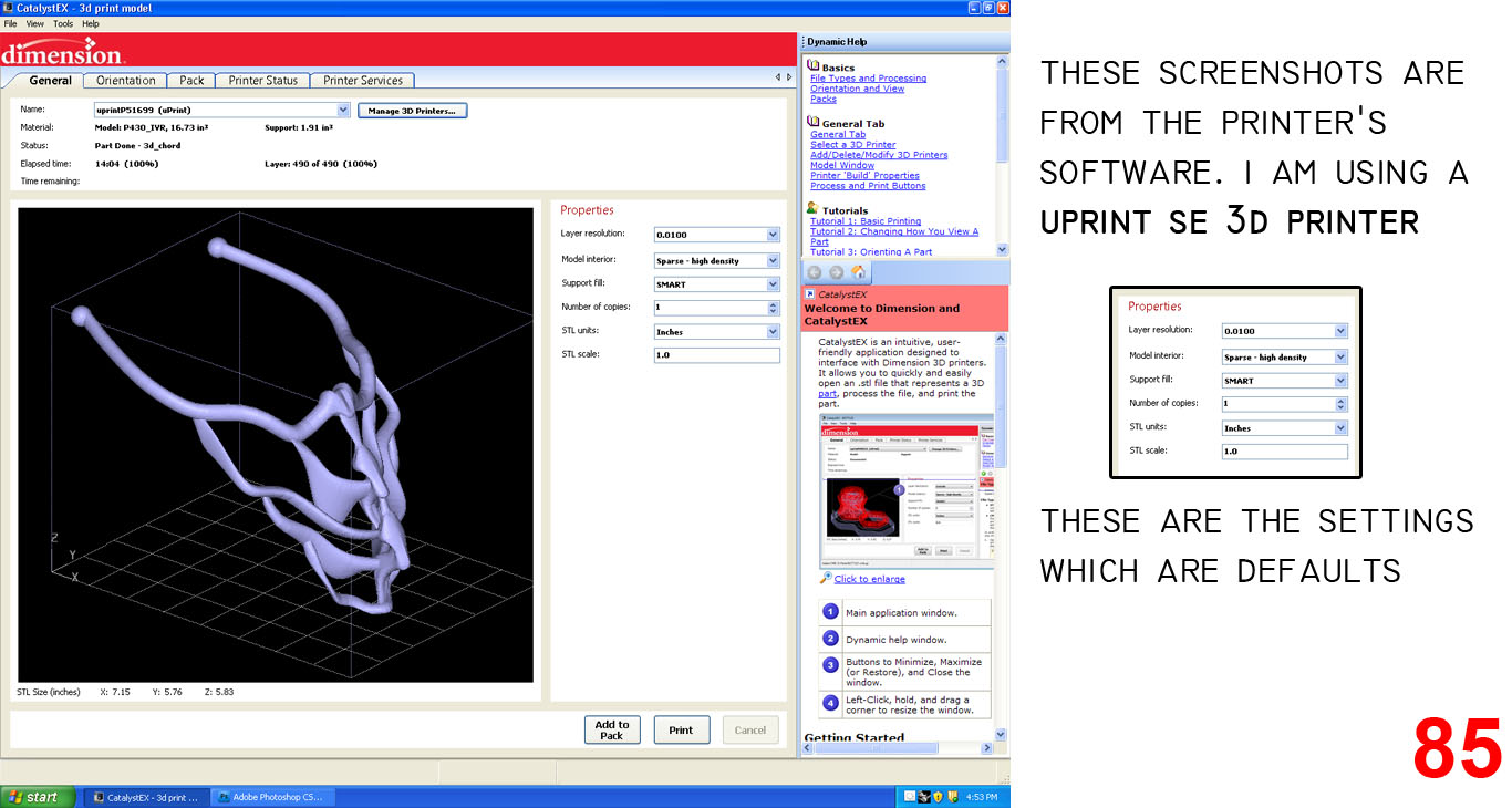
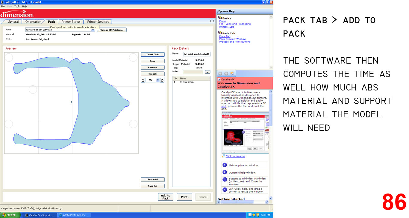
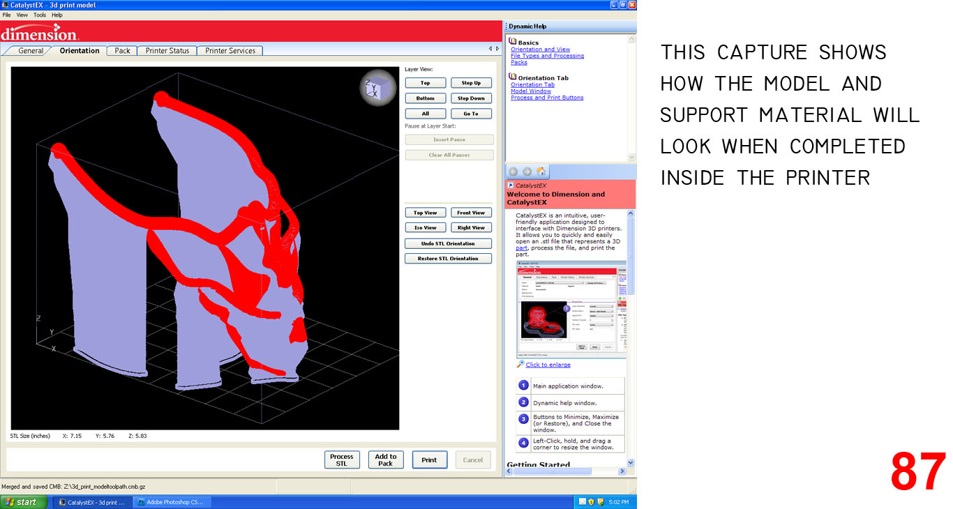
IMAGES 85, 86, 87 show the printer's software and the settings I used. The setting were default.
Now I wait for 15.5 hours and hope the model was well made!
Model Stats:
ABS Plastic Material (what the model is actually constructed with) = 3.03 cubic inches
Soluble Support Material (I have been told that this is possibly Carotin) = 5.43 cubic inches
Time to complete = 15 hours 32 minutes
Layer Resolution = .0100 in
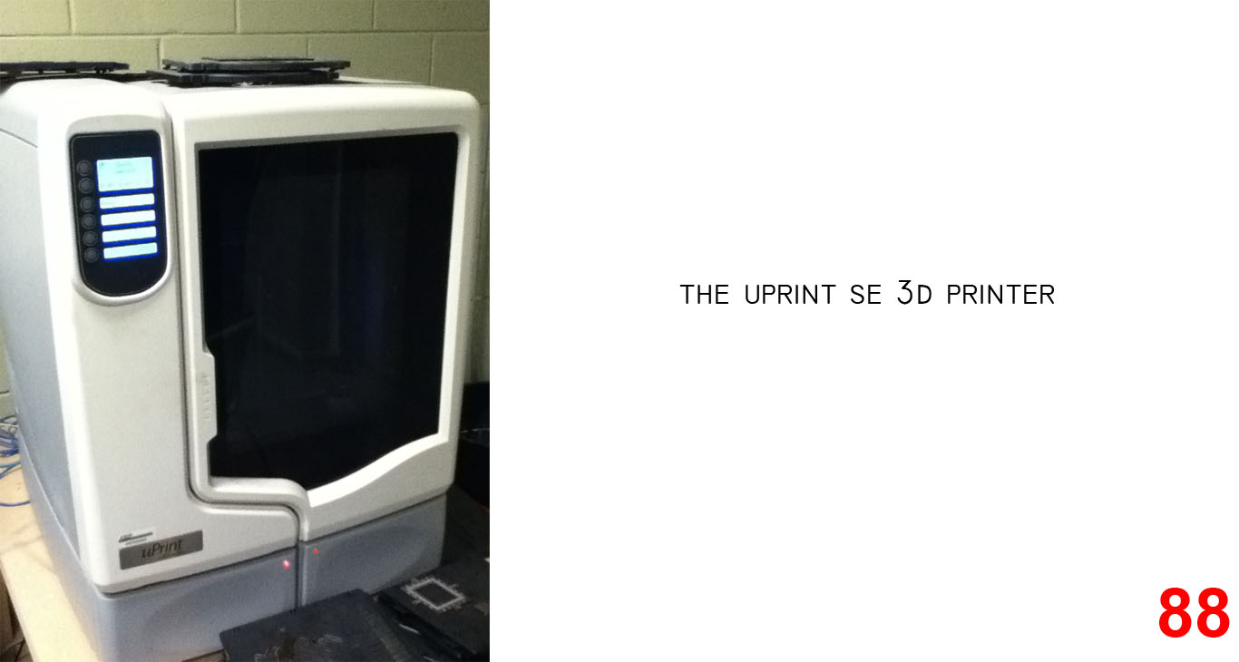
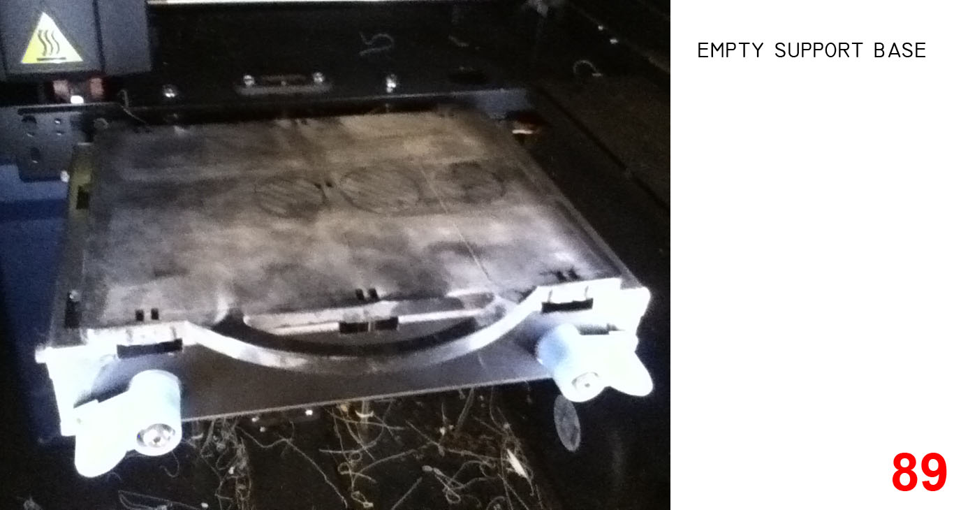
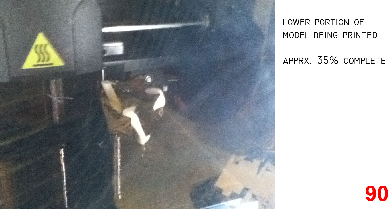
IMAGES 88, 89, 90 show the printer working on the early stages of the model.
REMOVING THE SUPPORT MATERIAL FROM THE PHYSICAL MODEL
Once the model is finished printing, the black support material needs to be removed. This can be done by machine most efficiently, but I do not have access to one. Instead, I mixed a solution of Lye into regular tap water.
I used 1 table spoon of lye to 1 gallon of hot water. You can break off some large chunks of support material prior to going in the lye solution.
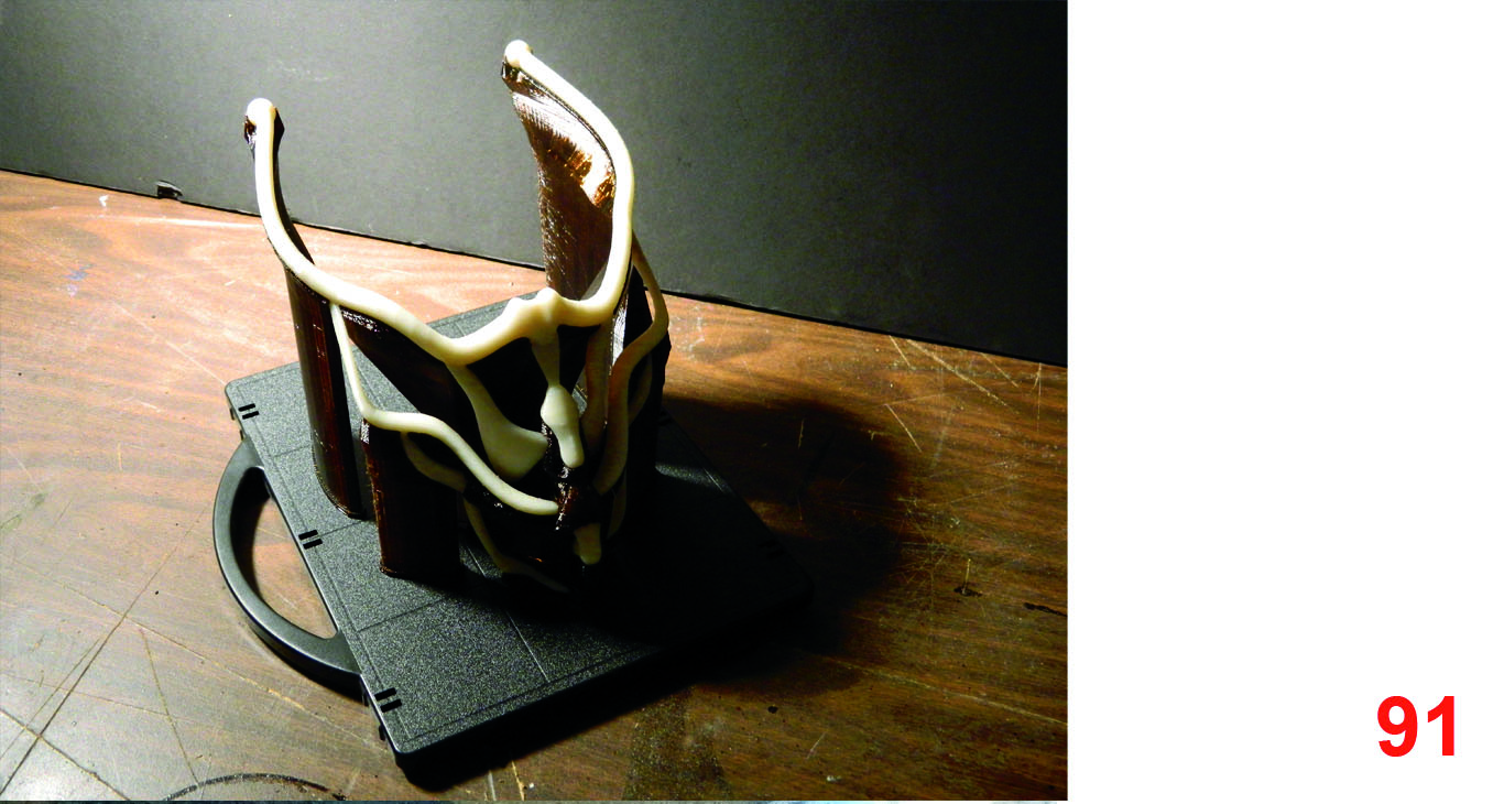
IMAGE 91 Shows the complete physical object, prior to lye bath with all the support material still intact.
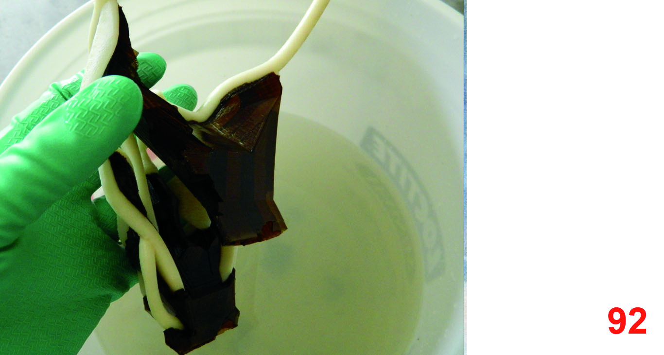
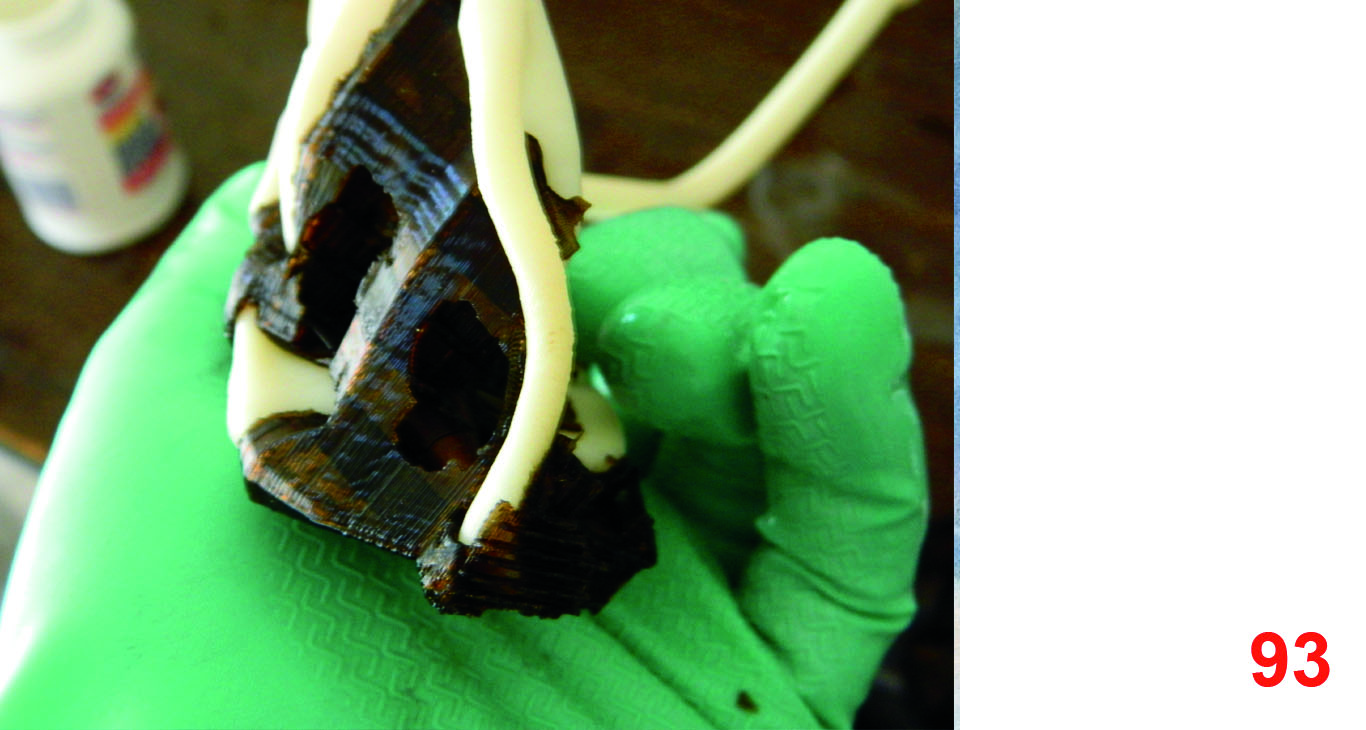
After 11 hours in the lye solution, I was able to remove a majority of the structure from the model. I changed the water, added the lye again, and after another 9 hours or so, the piece was completely free of support material.
IMAGES 92, 93 Show the progression through the lye
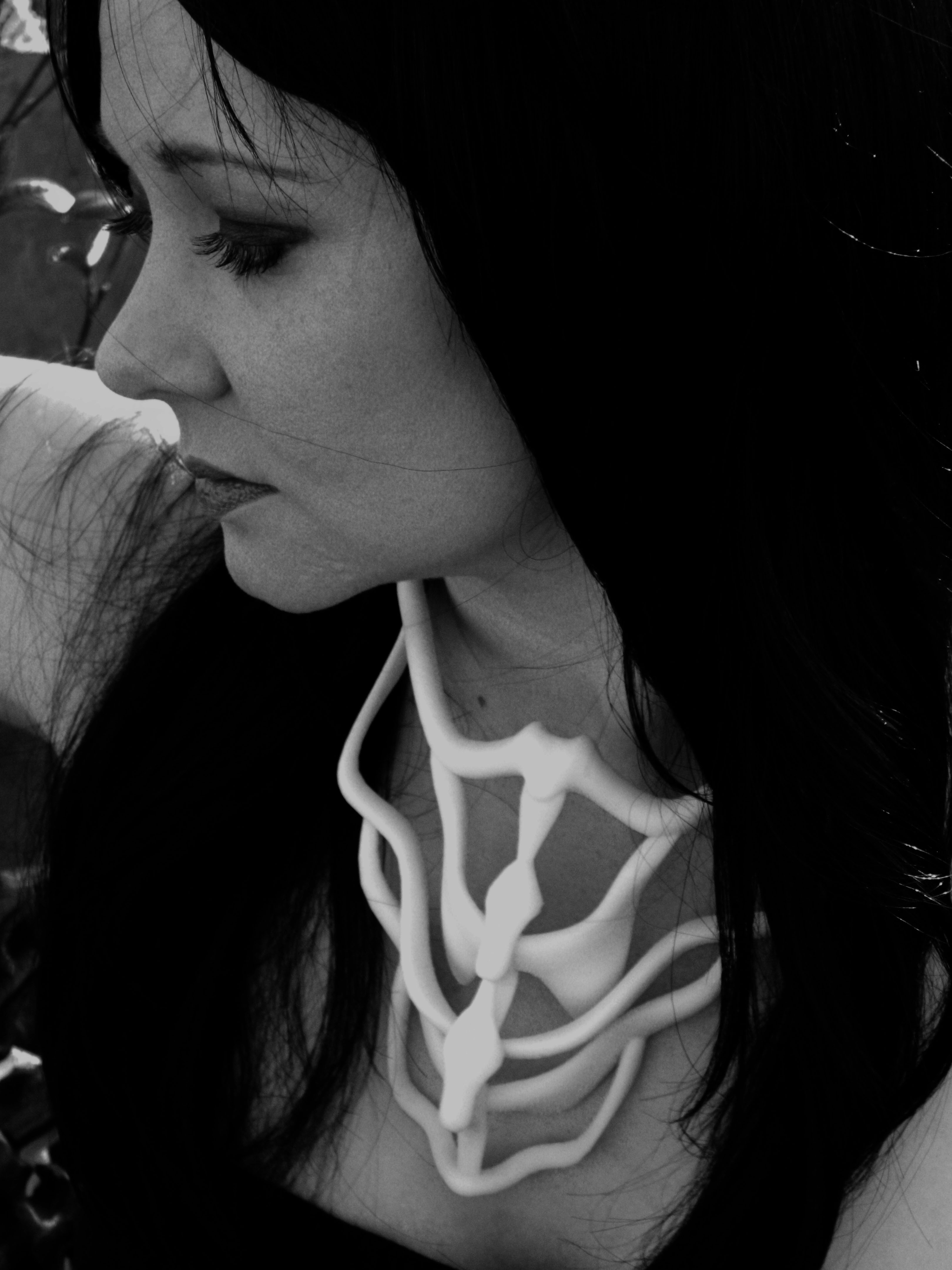
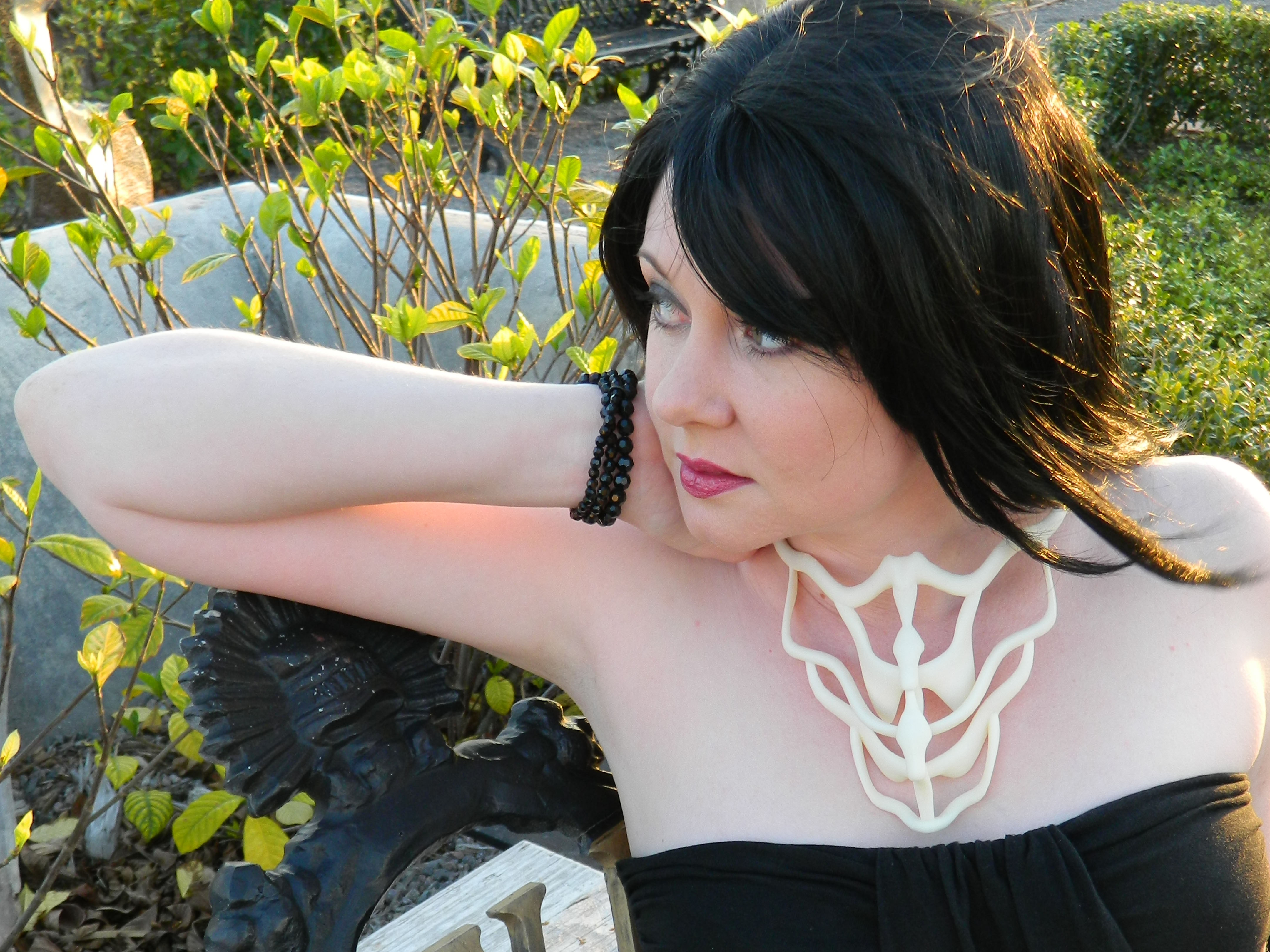
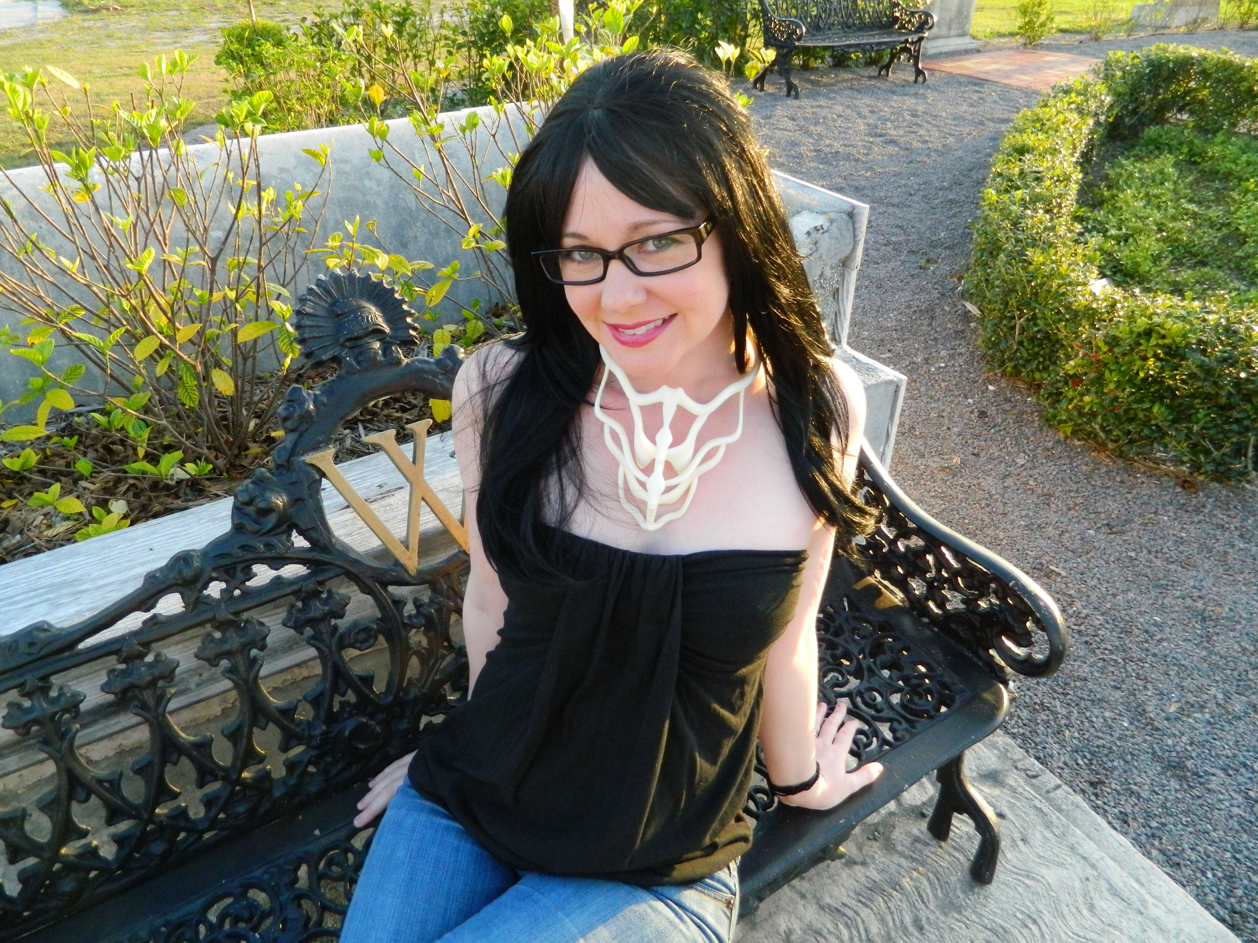
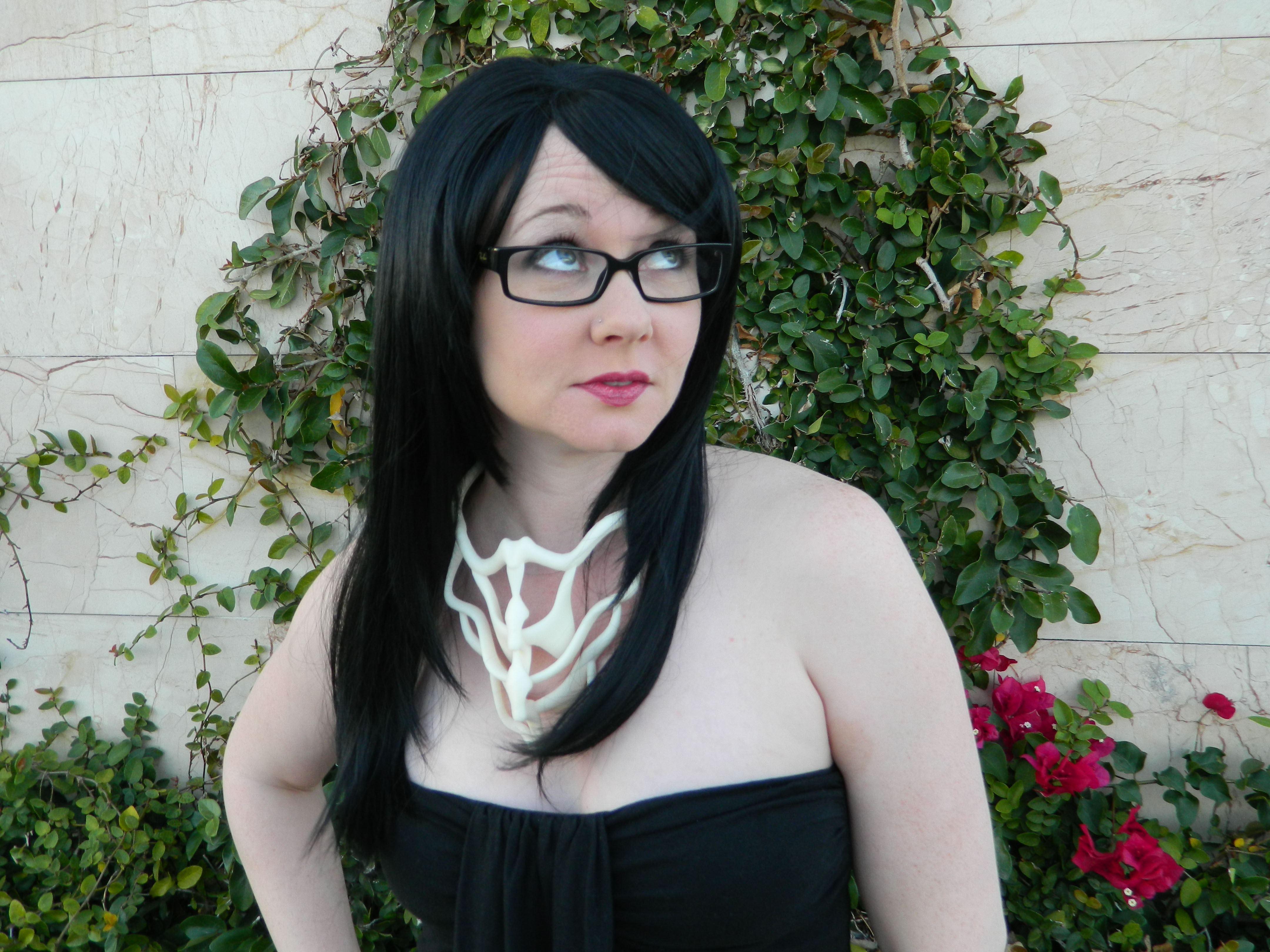
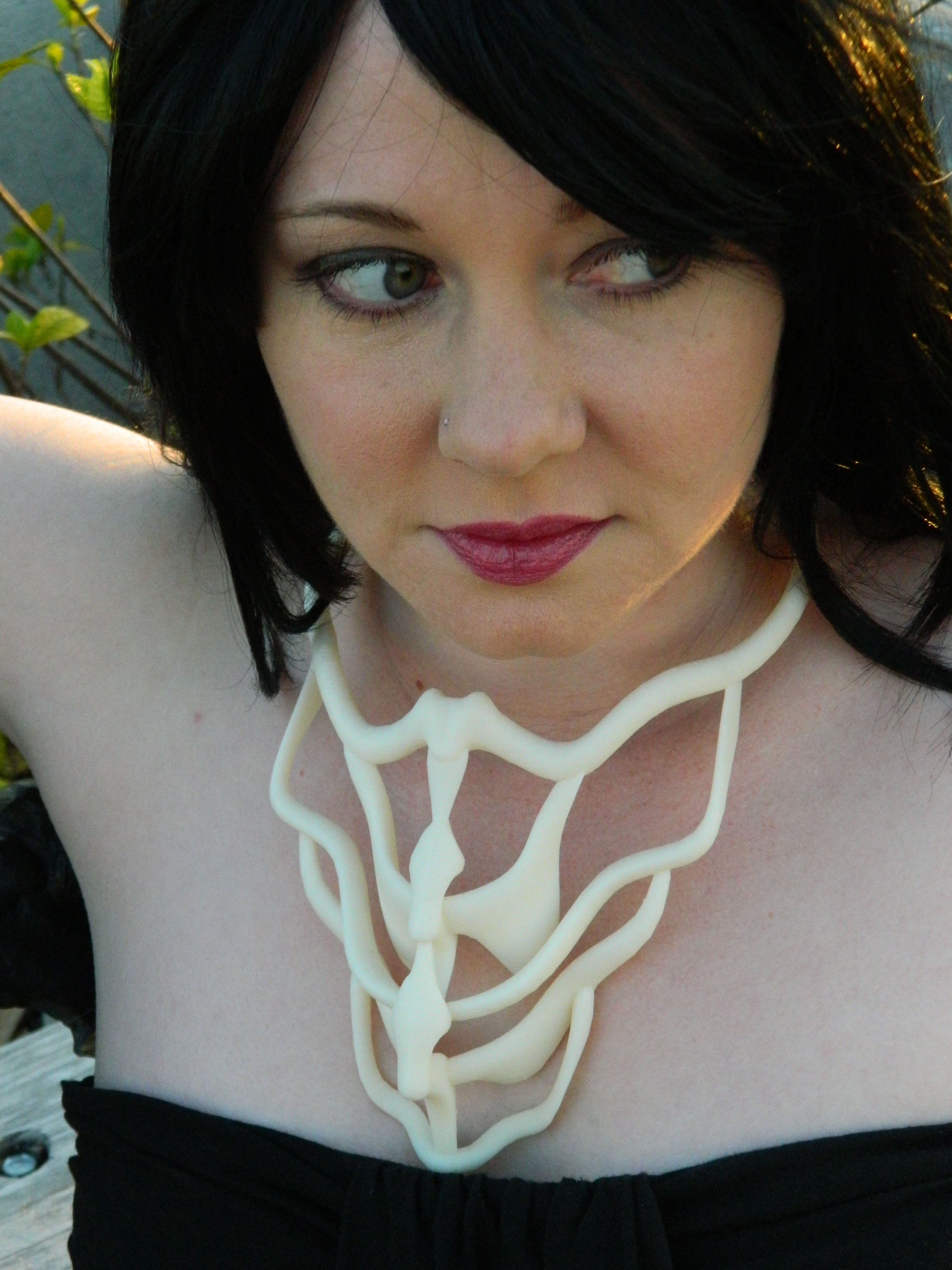
Completed Necklace