Sink Stopper Repair
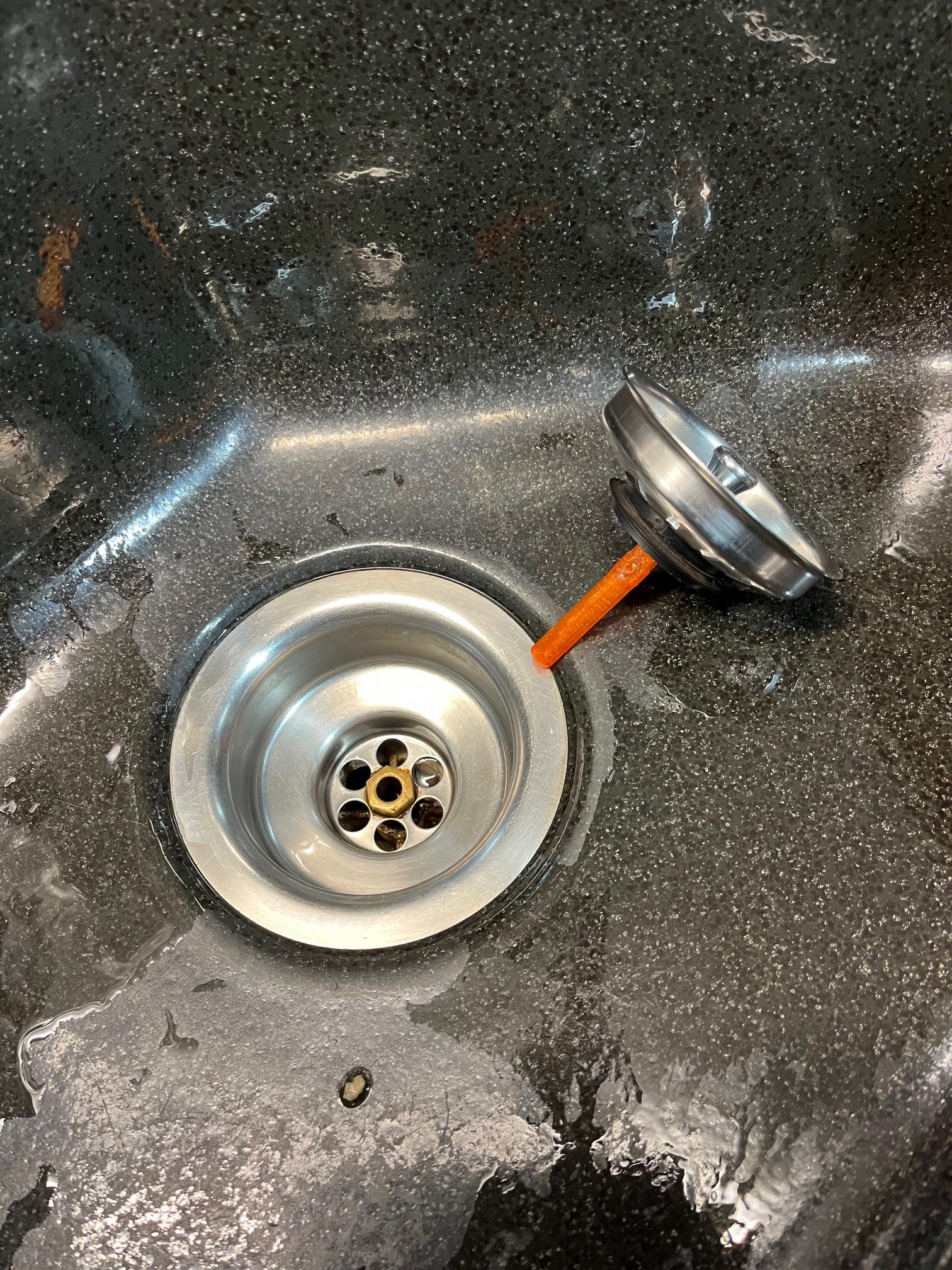
My grandparents have a sink that is very old. A small plastic piece from the stopper had broken off. Replacements didn't exist and a new sink would have cost way too much money. So I decided to design and print the replacement.
Supplies

- CAD Software (I used Fusion 360)
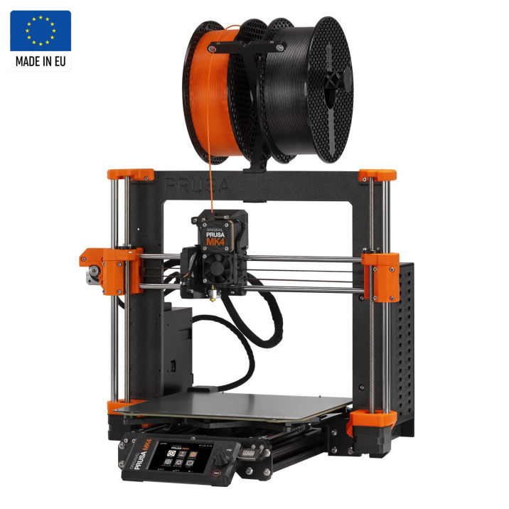
- 3D Printer
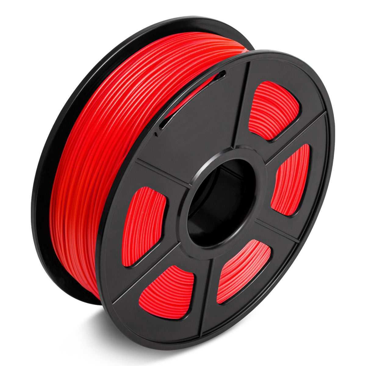
- 3D Printer Filament (something durable like PETG)
- Calipers
Measuring
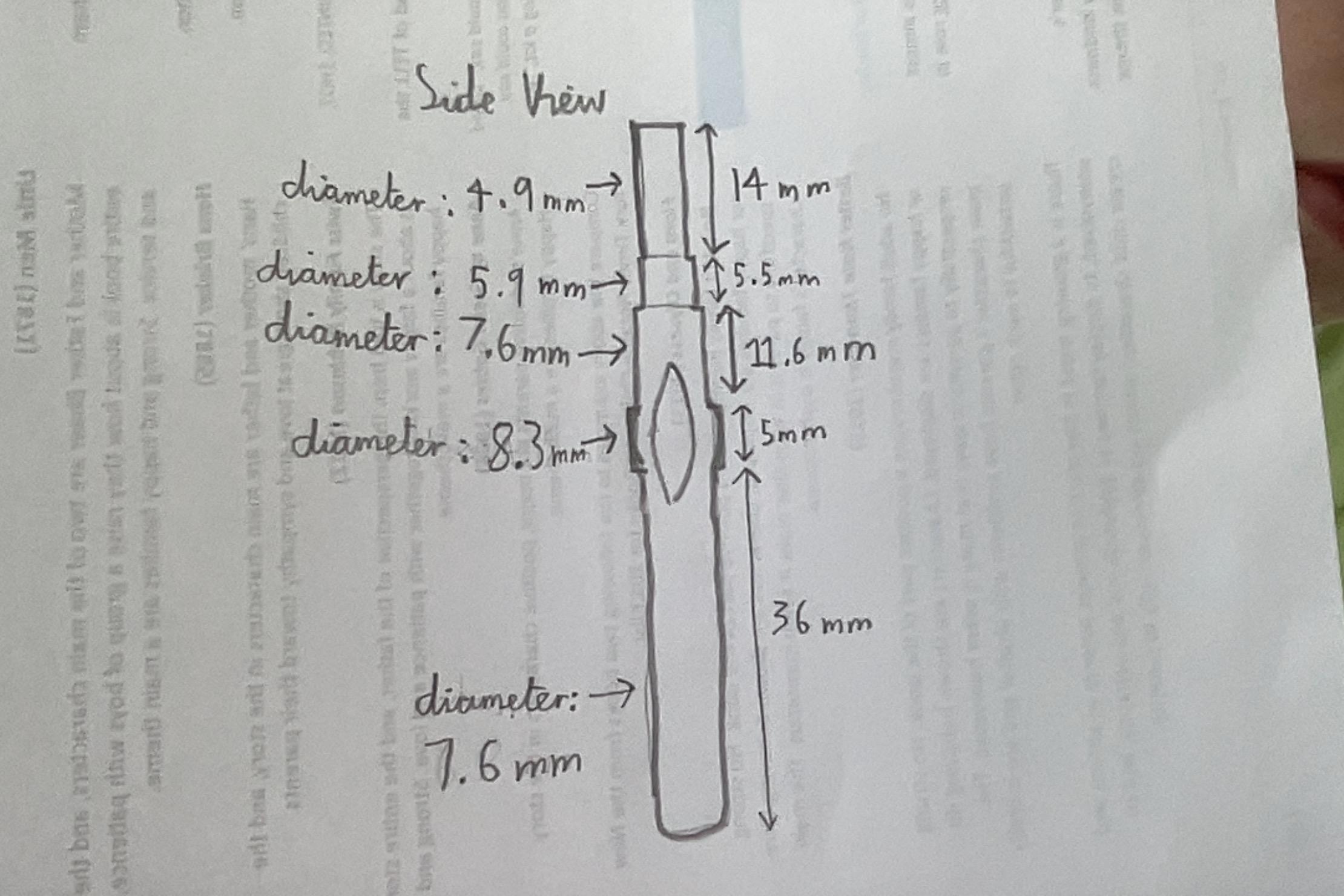
First pull out you calipers and take some measurements. You can write them down on a sheet of paper or you can do it digitally.
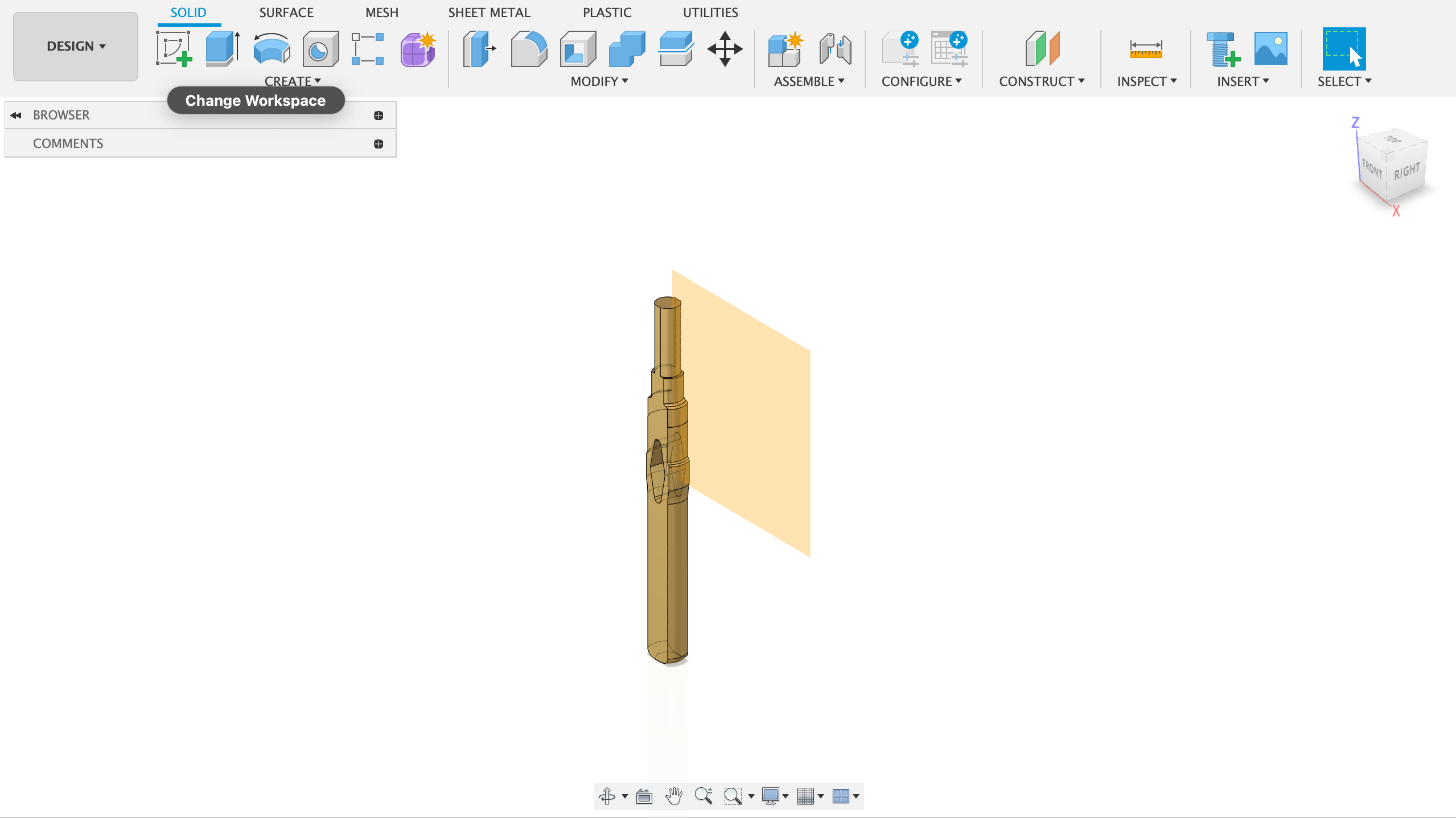
Designing the Base Structure
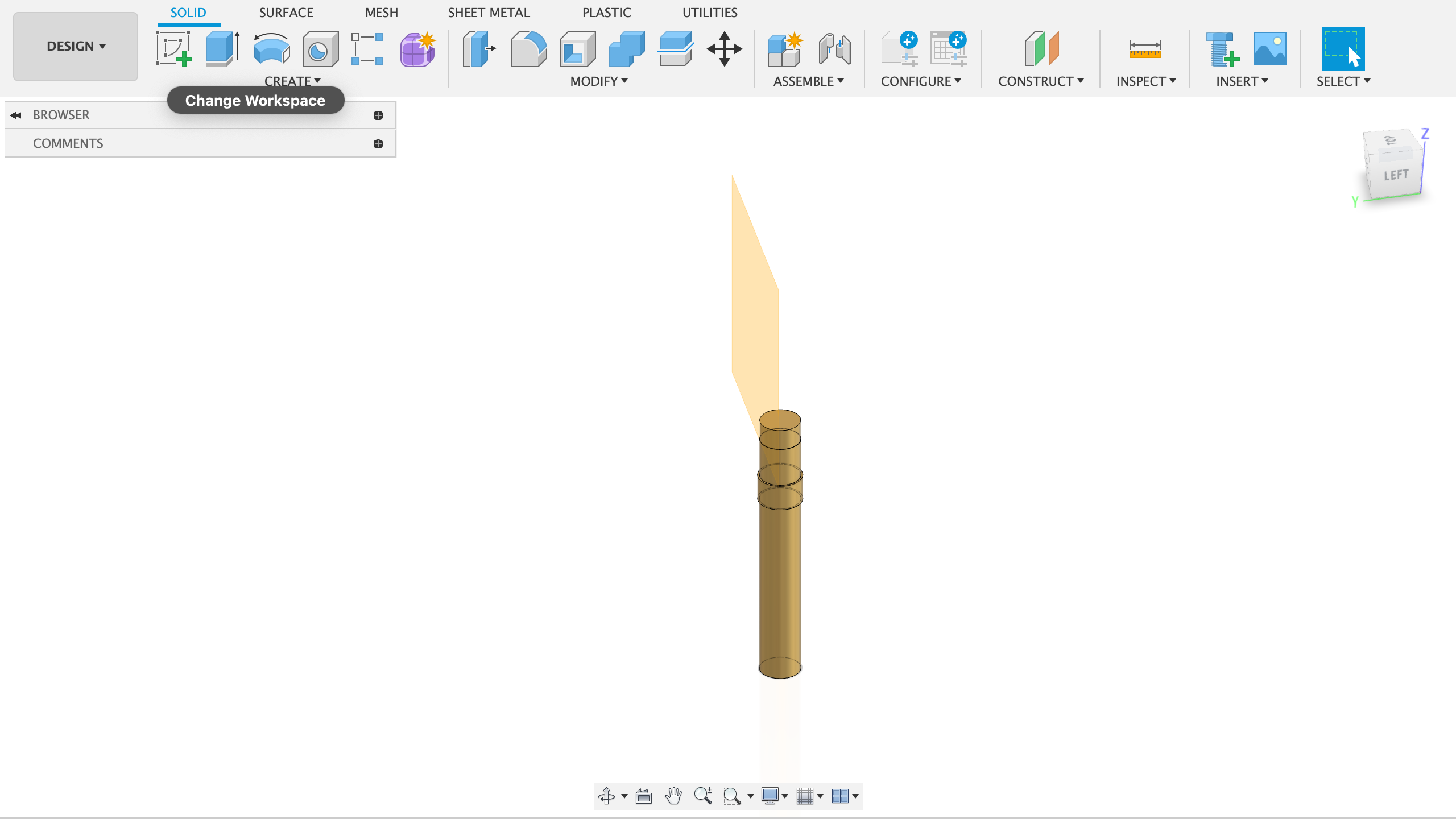
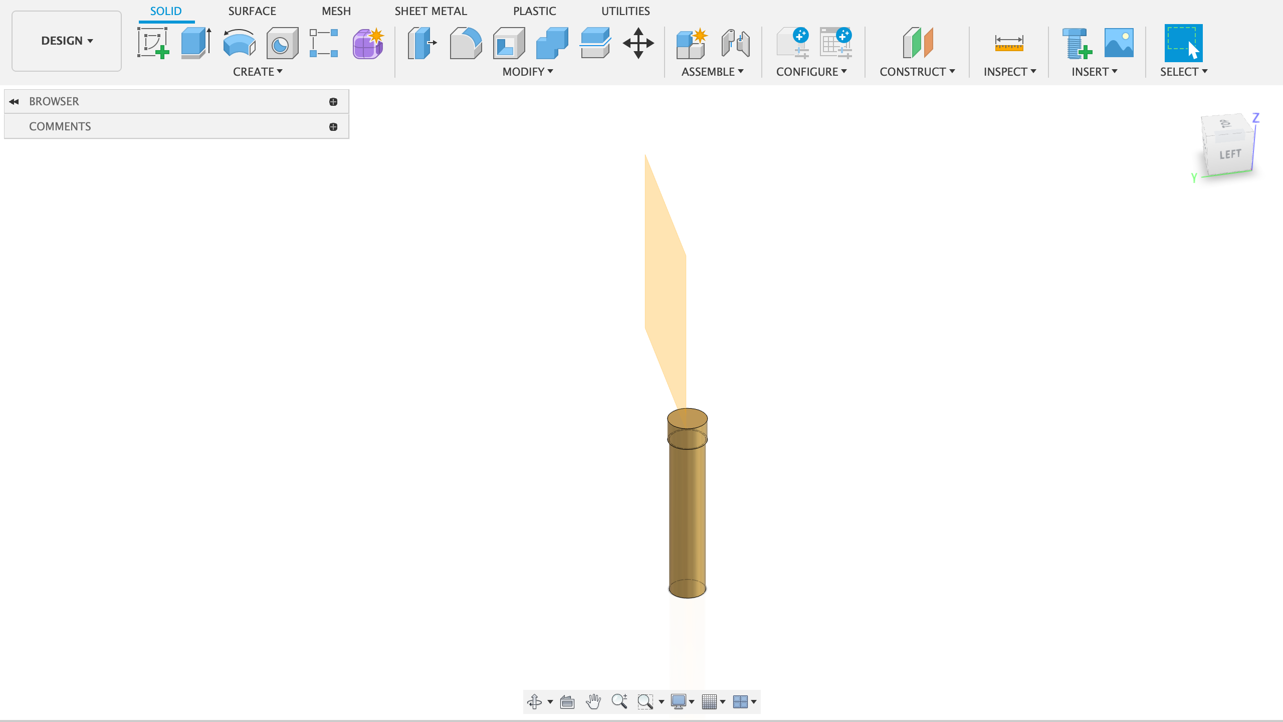
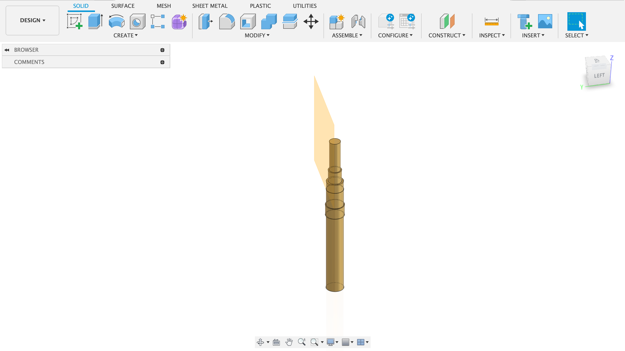
I started by basically stacking cylinders on top of each other.
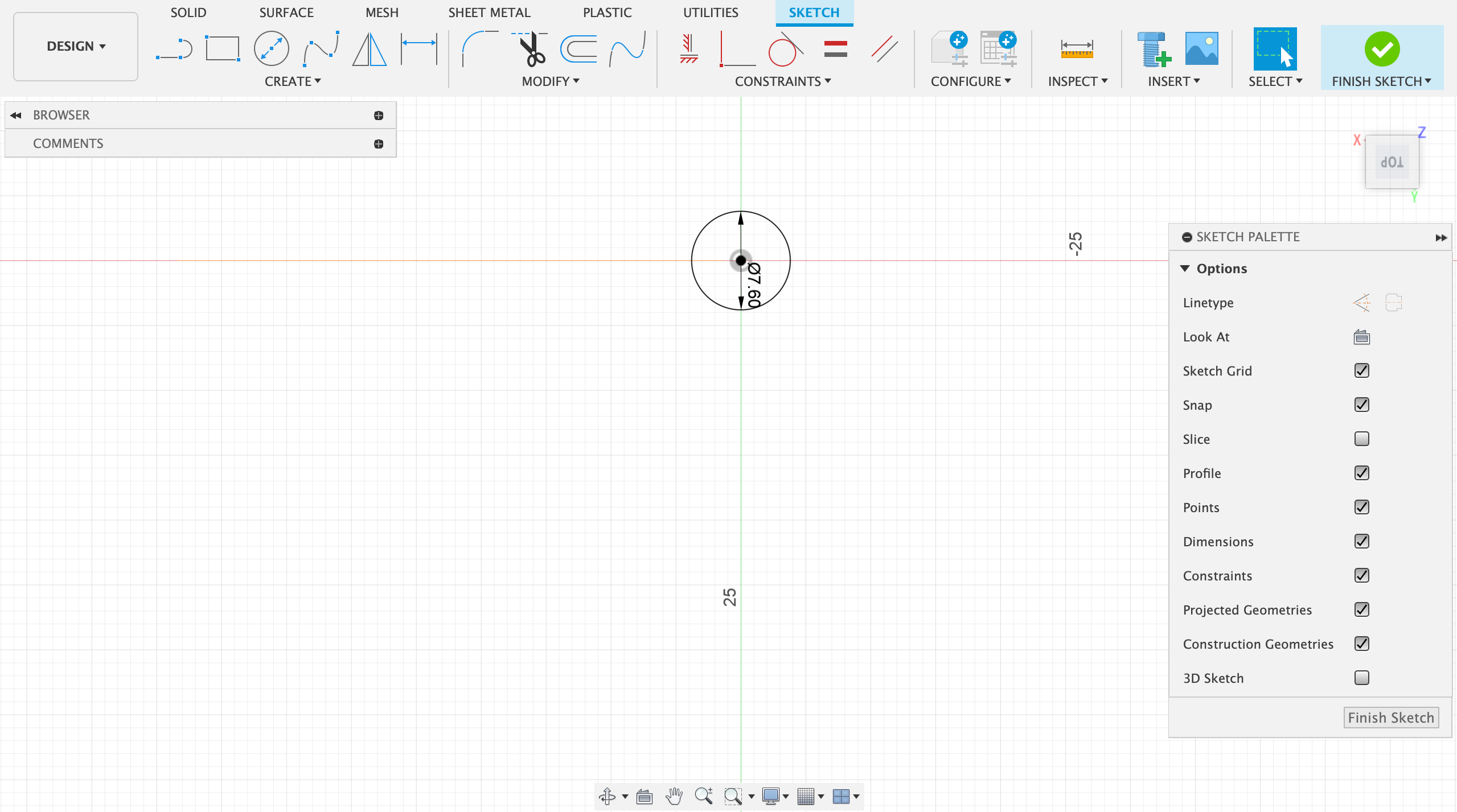
- Create a sketch on the bottom / xy plane
- Draw a circle around the origin with the measured diameter from Step 1
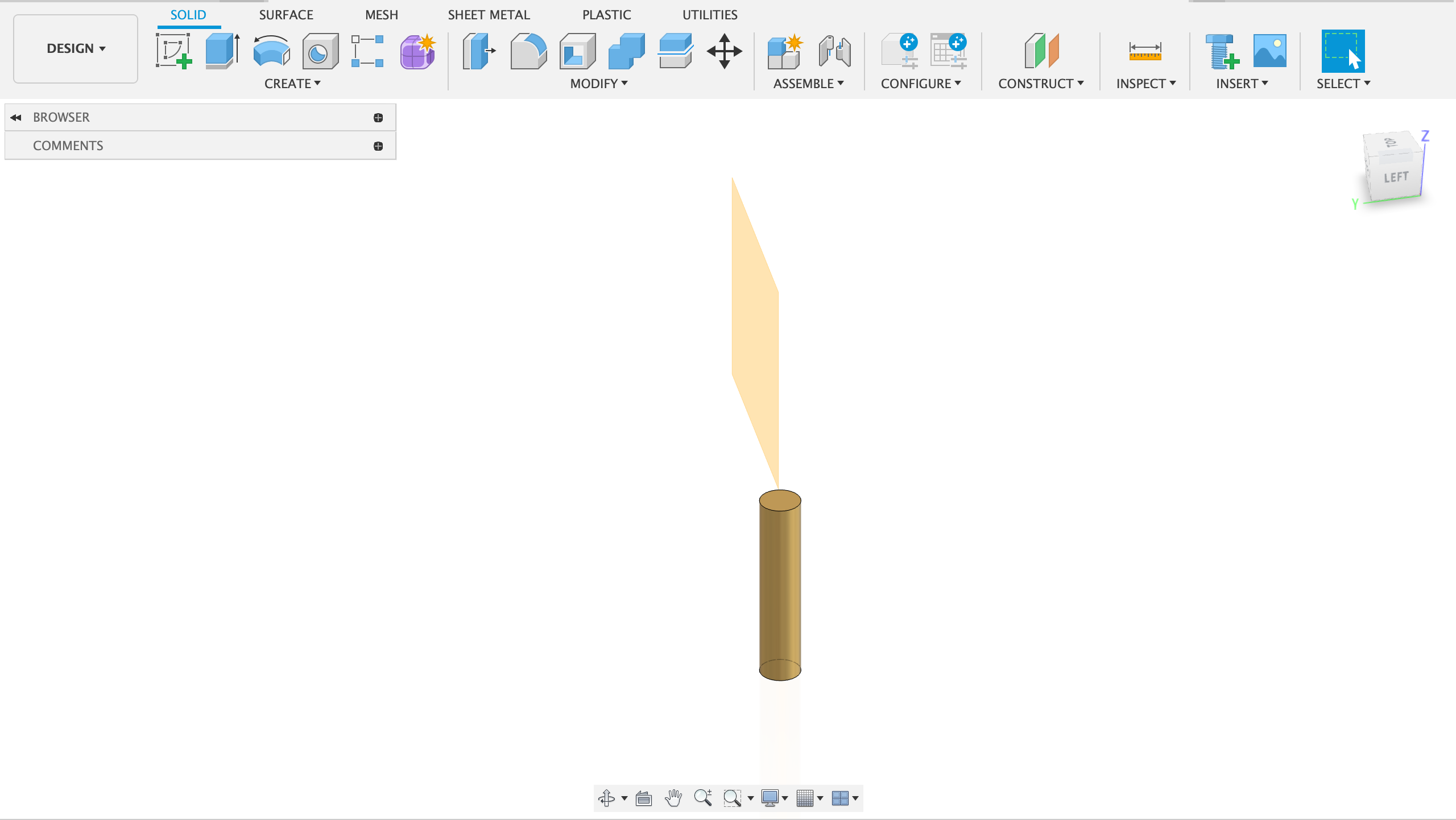
- Extrude the circle the measured amount from Step 1
- Create another sketch on the top face of the cylinder just created
- Draw a circle around the z axis with the next measured diameter from Step 1
- Extrude this sketch the desired amount
- Repeat until the base structure is done
Cutout to Allow Flexibility of the Part
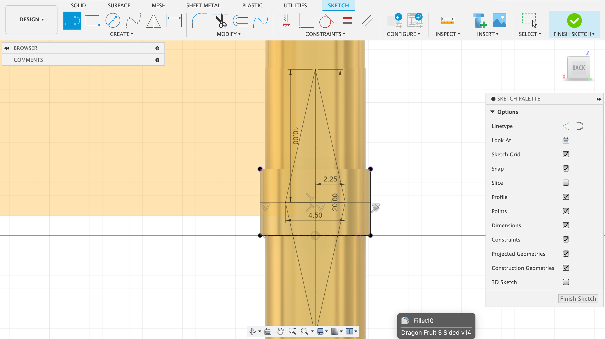
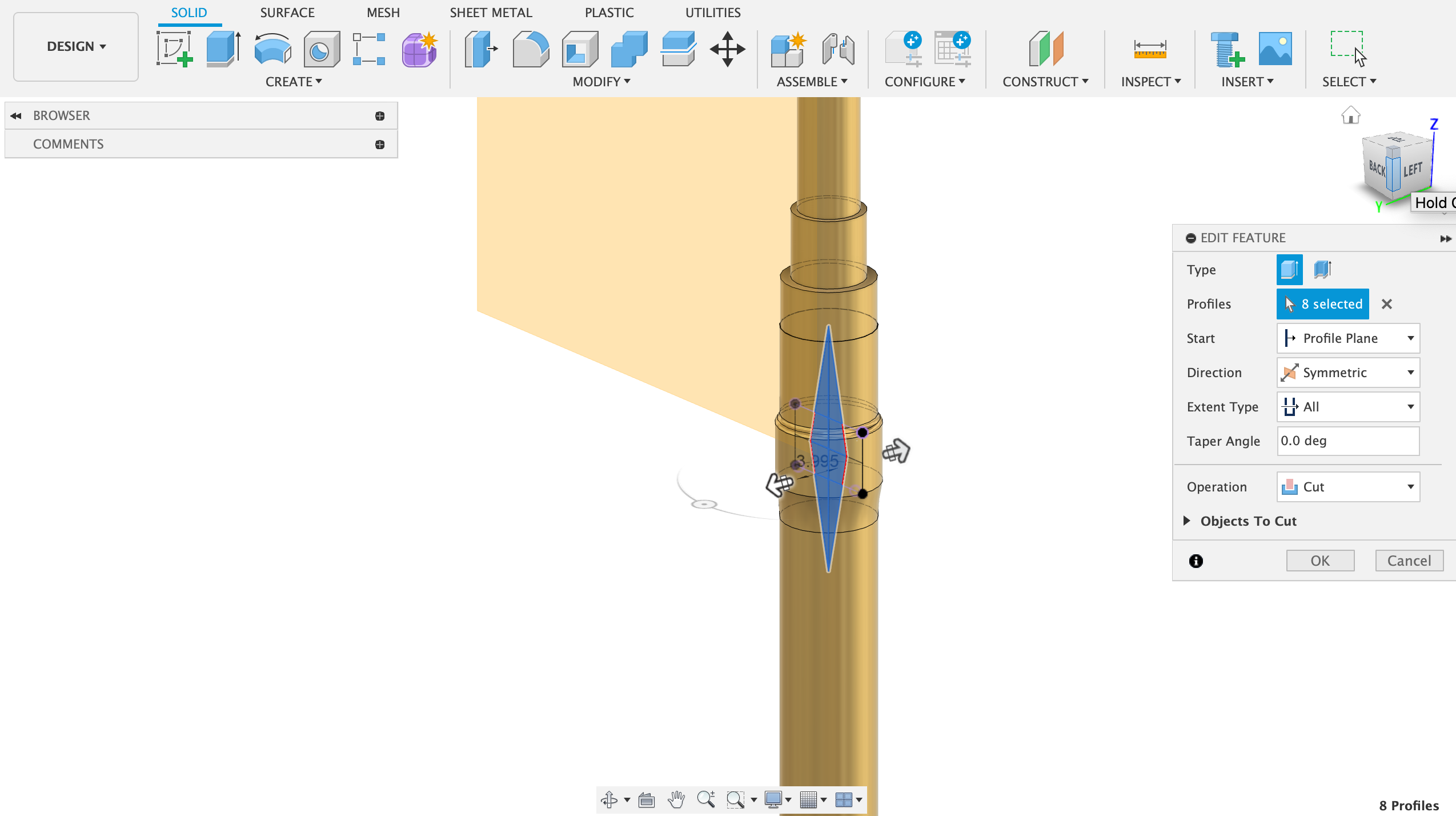
The injection molded piece had a hole to allow a portion of the part to flex in and out in order to open and close the sink-plug. I designed this cutout next:
- Create a sketch on the front plane
- Draw a point where the center of the cutout will be
- Draw two perpendicular lines and make sure that they cross in the point you created
- Draw a rhombus connecting these points
- Do a symmetrical cut through the entire part
Details

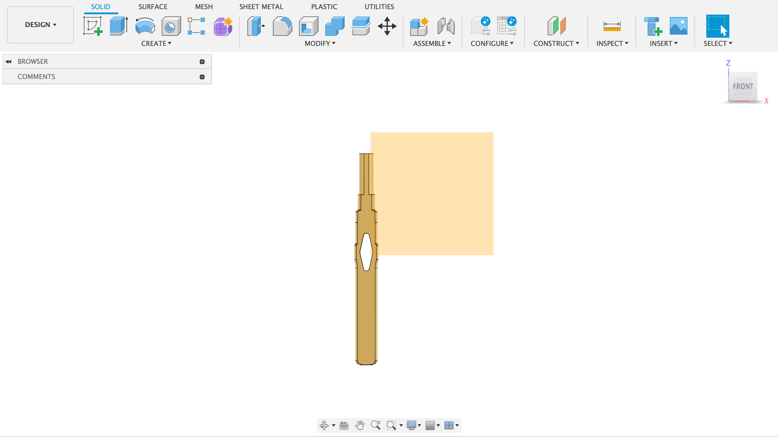
- Add fillets near sharp corners for rigidity
- (Optional) We will print the part on its side for optimum strength. This results in overhangs which need supports. You can cut off a portion of the cylinders (as seen in the picture) to make sure the part prints support-free
Slicing and Printing
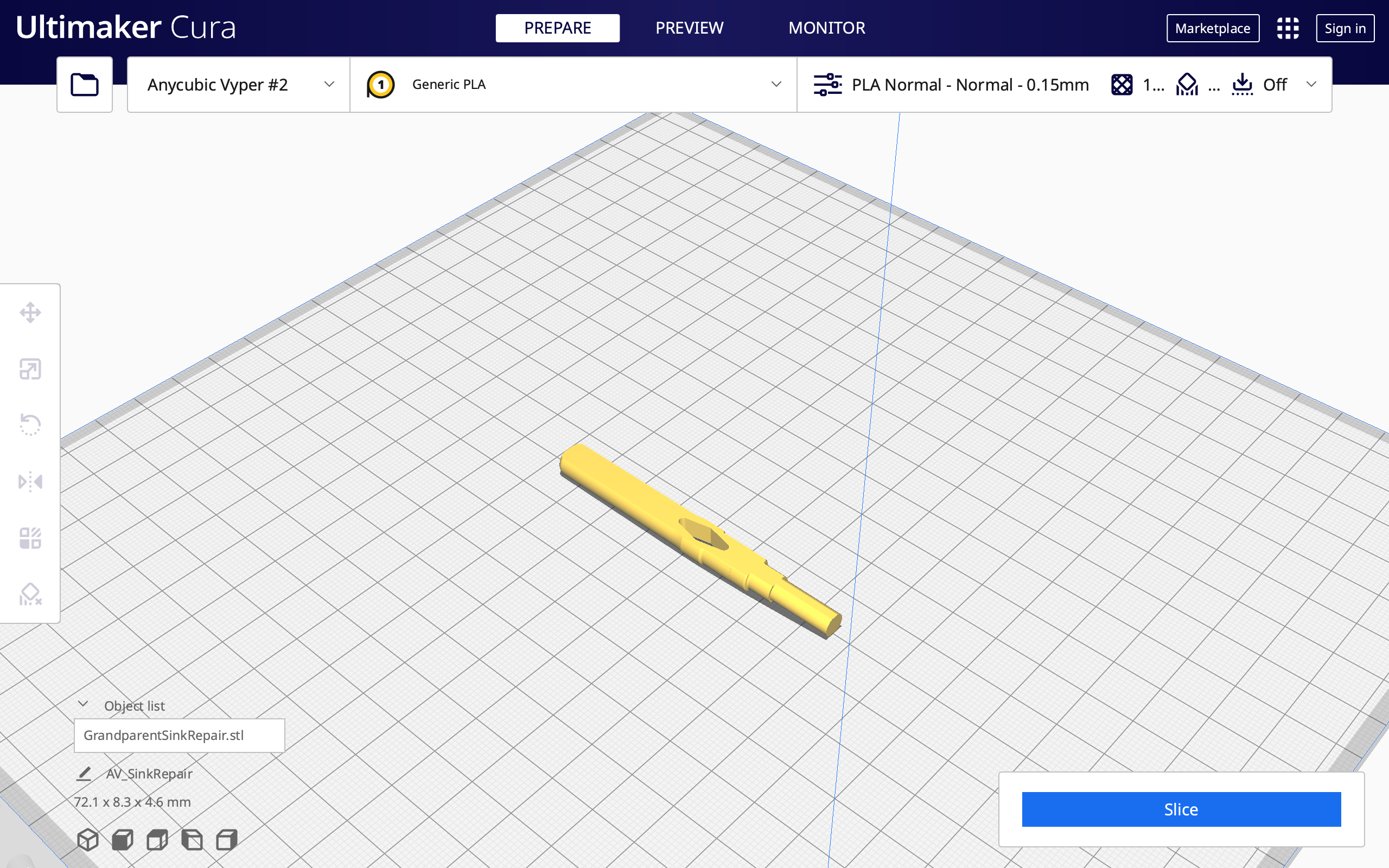
- In your slicer, place the part on its side
- Enable supports (not needed if you did the optional step in Step 4)
- Slice and print
Making Changes
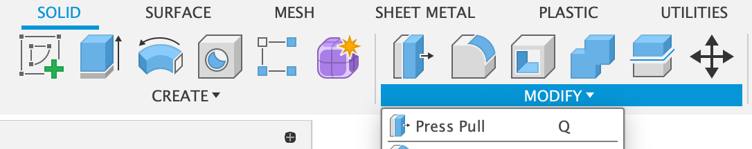
If the part doesn’t fit make some changes using the "Press Pull" feature in Fusion 360.
(Optional) Sand the part smooth
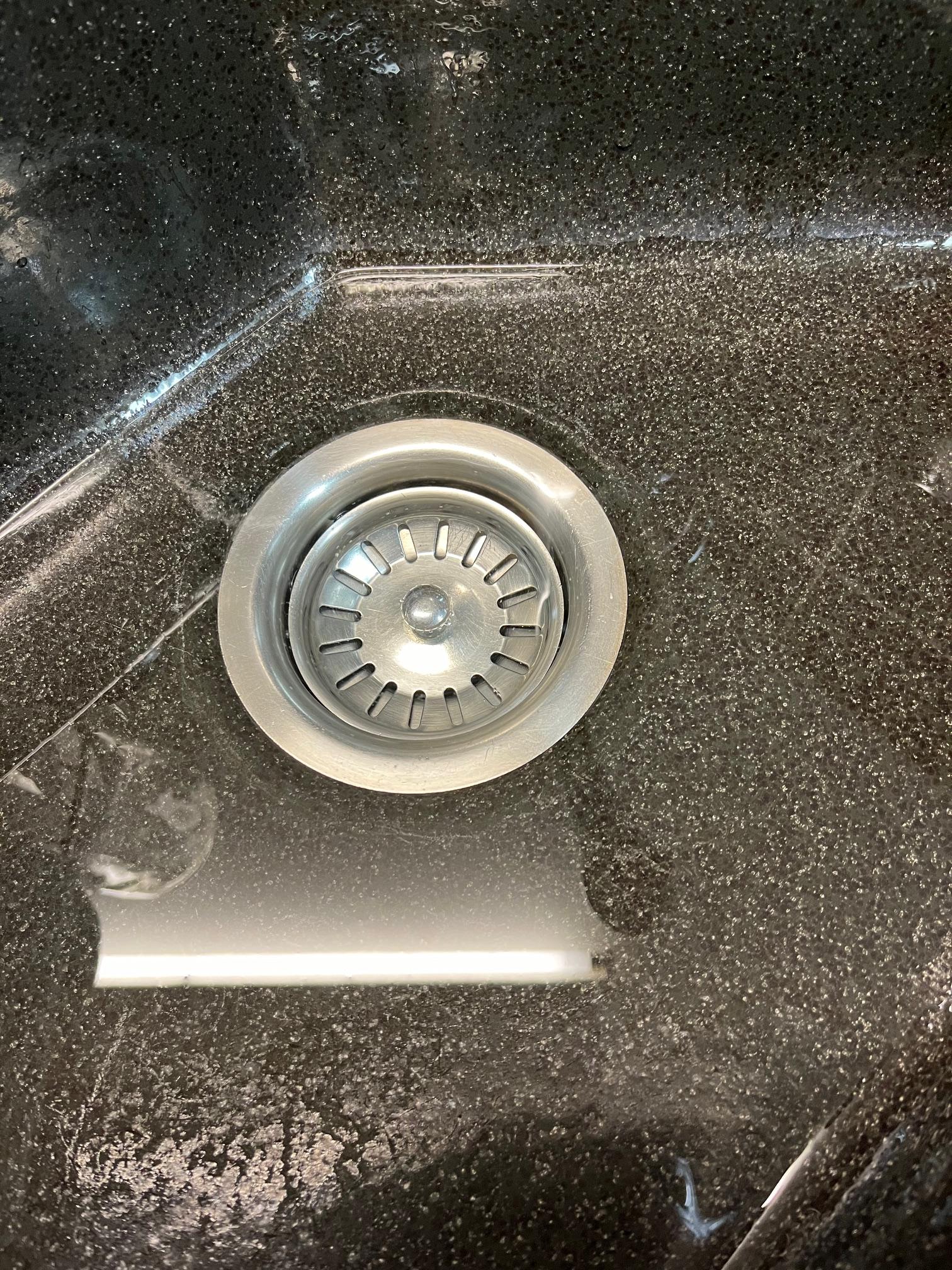
Done
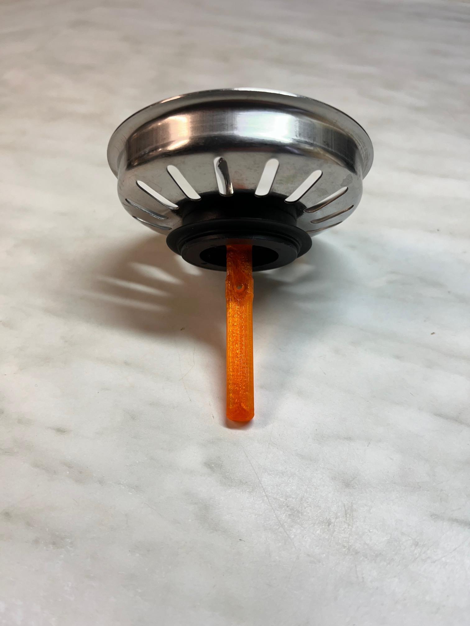
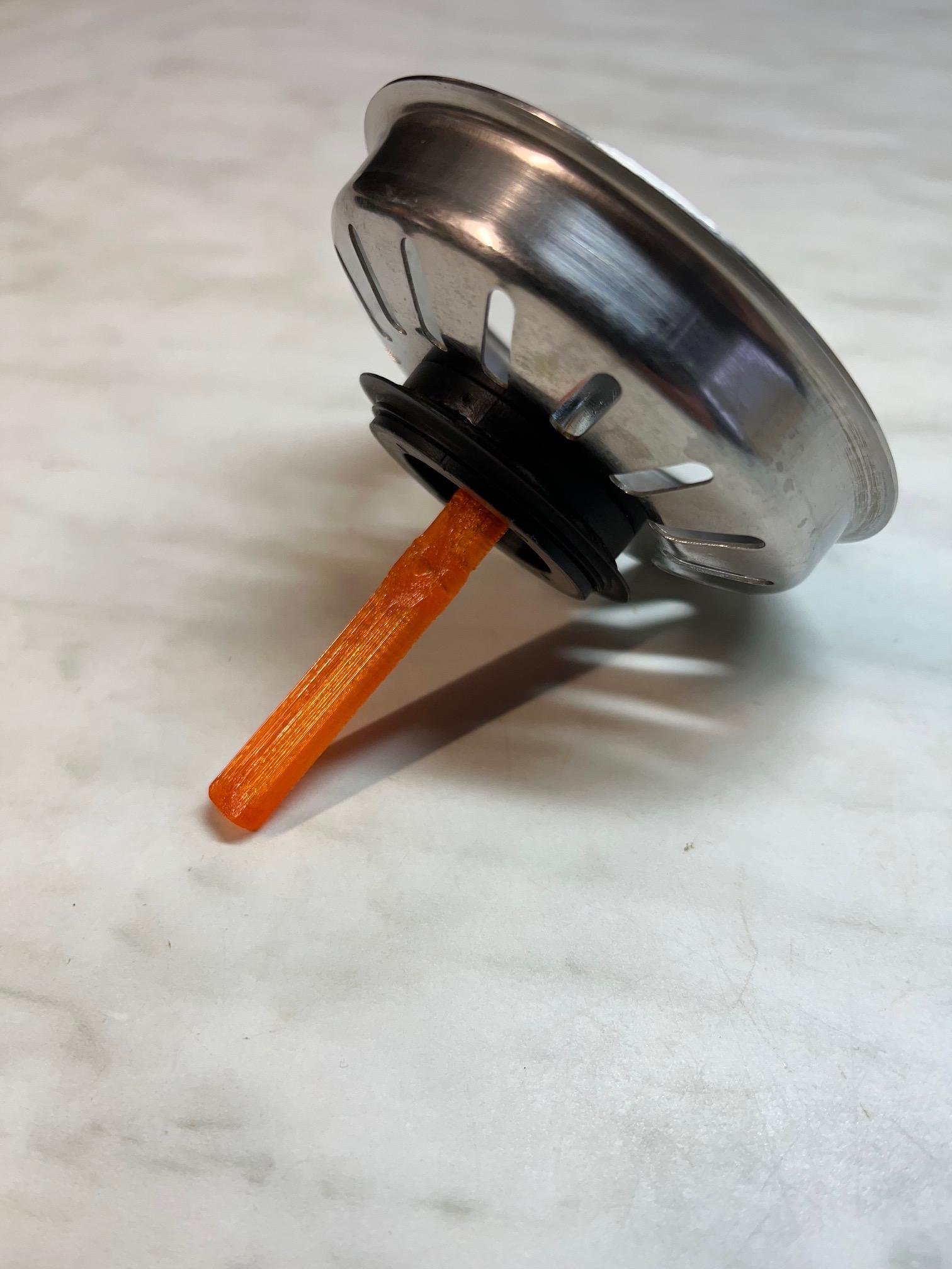
You're done!