Sinilink WiFi Switch Modification With INA219 Voltage/Current Sensor
by mmrx in Circuits > Electronics
3232 Views, 4 Favorites, 0 Comments
Sinilink WiFi Switch Modification With INA219 Voltage/Current Sensor

The Sinilink XY-WFUSB WIFI USB switch is a nice little device to remotely turn on/off an attached USB device. Sadly it's lacking the ability to measure the supply Voltage or used Current of the attached device.
This instructable shows you how I modified my USB switch with an INA219 Voltage/Current sensor. With this modification you can monitor an attached device's power consumption, e.g. a smartphone, ebook reader etc., during charging and automate to turn off power to the attached device before it is charged to 100% to (maybe) extend the life of the integrated LiPo battery.
Be aware that in the end this modification results in a slight voltage drop of the 5V input to the output of the module.
Prerequisites/Parts
You will need the following parts:
- Sinilink XY-WFUSB WIFI USB switch
- INA219 Voltage/Current sensor module (a smaller one is better)
- 0.4mm diameter enameled wire
- thick wire, which can handle 2-3A of current
- heat shrink tube matching the thick wire
- 25.4mm diameter heat shrink tube
- The usual tools like solder iron, solder, flux
- PC where you can compile Tasmota with INA219 support
General Module Description
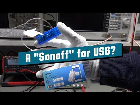)
A very good general description of the USB switch module, its parts and how to open it is done in the linked video from Andreas Spiess. This video inspired me to make the changes to my module with an INA219 sensor module.
ESP8285 Unused GPIOs
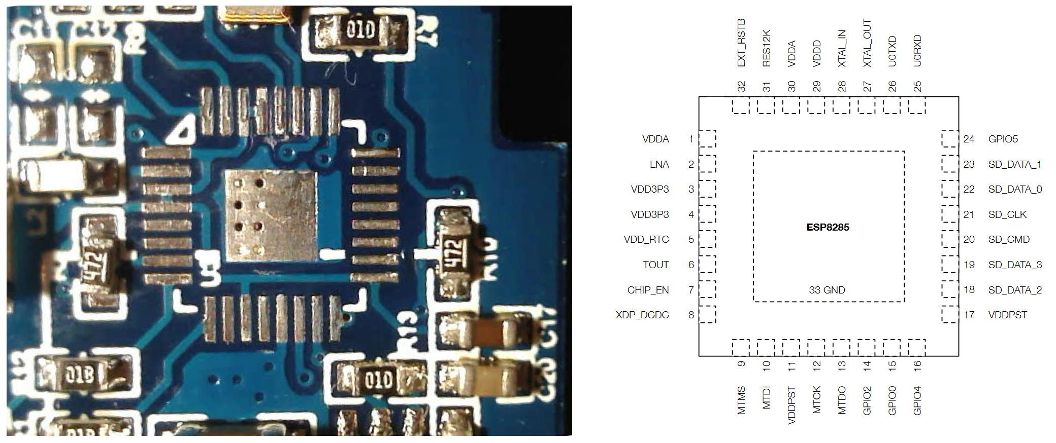
To figure out which Pins/GPIOs of the ESP8285 are not connected I removed the chip from the module. You do not need to do this, just look at the picture.
With the desoldered chip and the ESP8285 datasheet you can see that the following Pins/GPIOs are unused:
- PIN10 / GPIO12
- PIN12 / GPIO13
- PIN18 / GPIO9
- PIN19 / GPIO10
- ... and more ...
You need only two for the I2C connections (SDA + SCL) to the INA219 module. I first picked PIN18 + PIN19 but I destroyed the pads when soldering to it because I'm not (yet) skilled enough to solder two 0.4mm wires at that pin pitch when they are side by side.
Solder Current-carrying Wires to the PCB
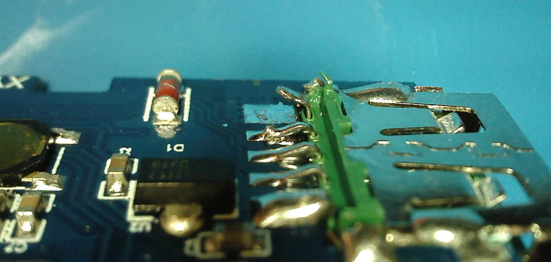
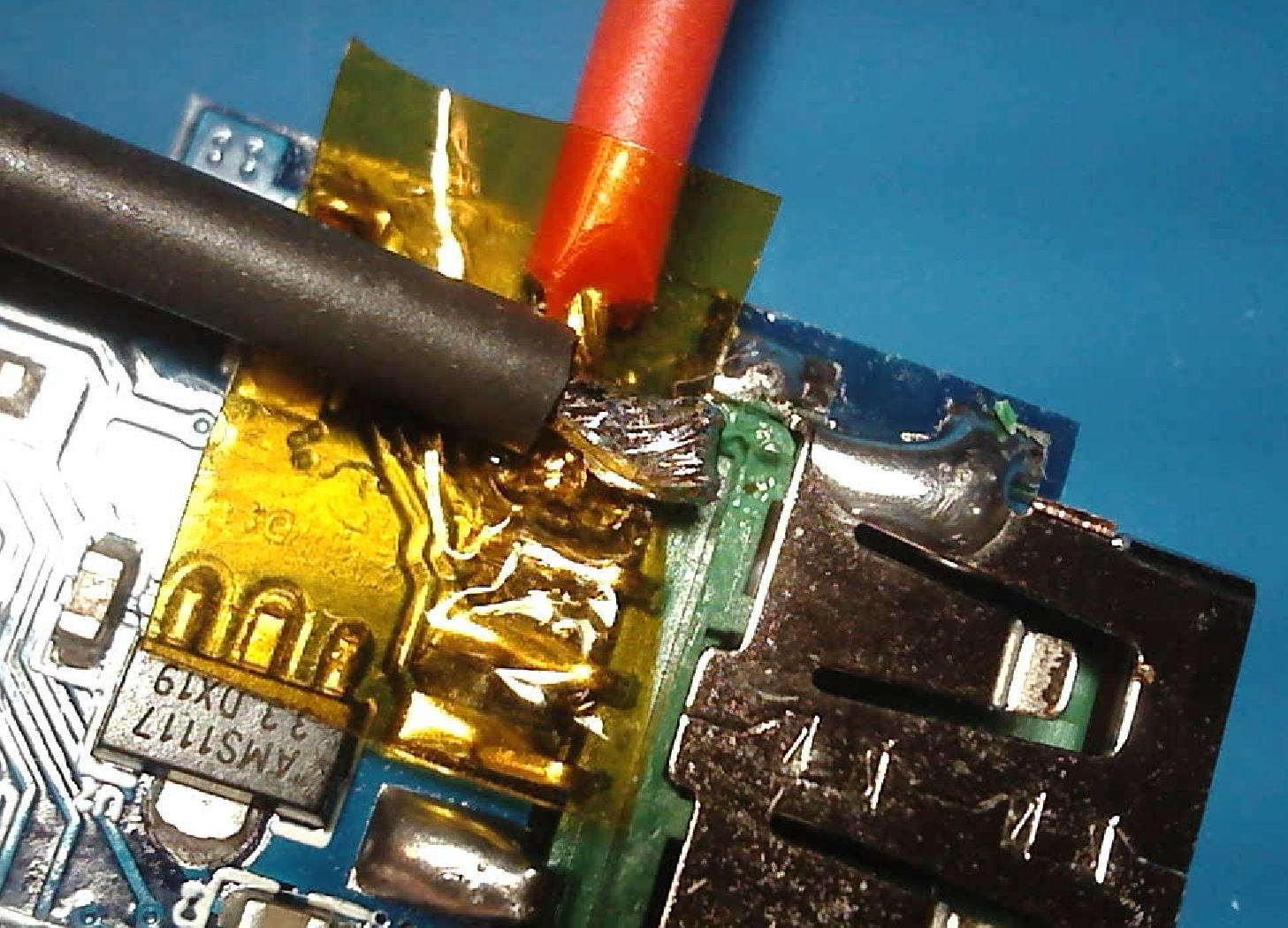
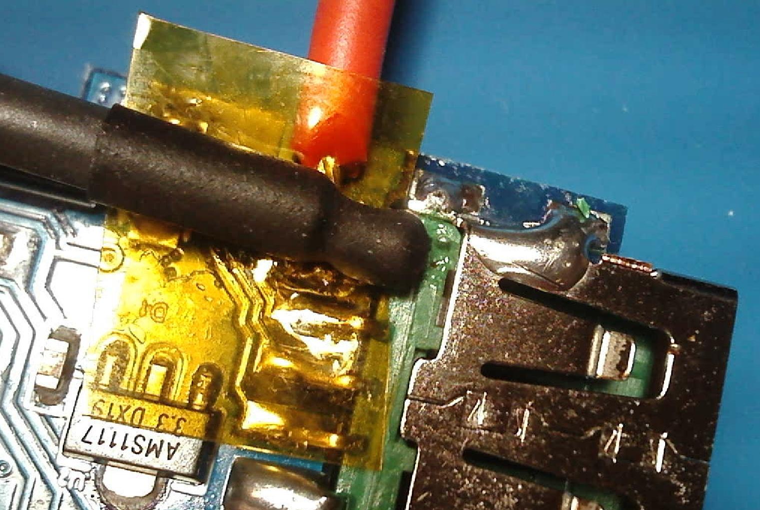
To measure the current the INA219 module needs to be inserted into the output +5V feed between the switching MOSFET and the USB output port.
First lift the leg of the USB socket.
Second solder a thick wire (red) to the pad on the PCB, which is the output of the MOSFET on the other side of the PCB, this wire will go to "Vin+" of the INA219.
Then solder a thick wire (black) to the Pin of the USB socket, this will go to "Vin-" of the INA219.
I put some heat resistant Kapton tape between them while soldering and afterwards added some heat shrink tubing around the black wire. I also left the Kapton tape in place.
Solder Data Wires to the ESP8285 Pins
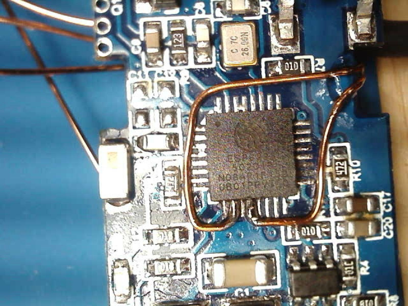
Pre-bend the wires before soldering them to the chip, you shouldn't put to much strain on the pads attached to the pins of the chip.
Solder two wires to pin 10 and 12 of the chip.
As you see on the picture I burned away the pins 18 and 19 on the right side of the chip, so try to keep the heat low and soldering duration short.
I also glued down both wires at the edge of the board to have a bit of strain relief.
Solder Vcc/Gnd Wires to 3V3 Regulator and USB Port
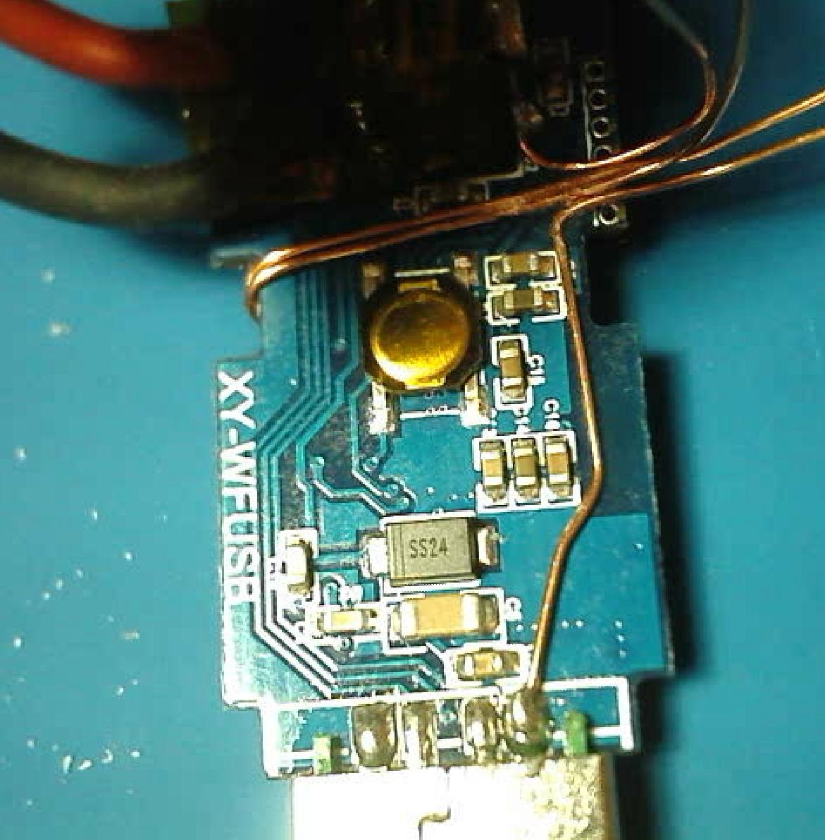
Solder a wire to the output of the AMS1117 3V3 voltage regulator, this will go to "Vcc" of the INA219 module. (Sorry for the bad picture)
Solder a wire to the Gnd pin of the USB male jack, this will go to "Gnd" of the INA219 module.
Solder Wires to INA219 Module
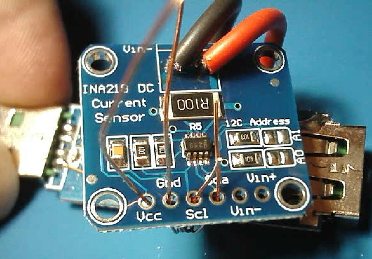
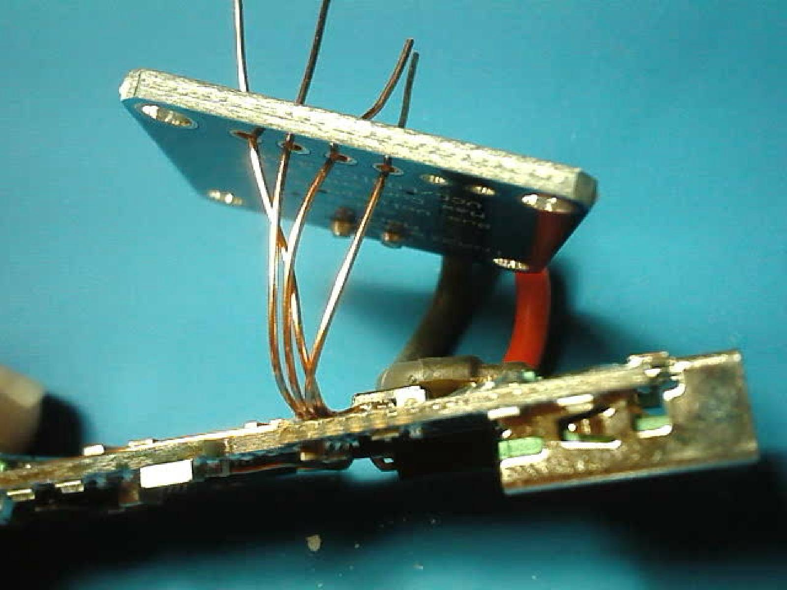
Solder the six wires to the INA219 module. Keep enough space between the main PCB and the module to insert the blue cover of the Sinilink device.
- Vin+ - (red) from pad on PCB
- Vin- - (black) from pin of USB output socket
- Vcc - from AMS1117 3V3 voltage regulator
- Gnd - from Gnd pin of the USB male jack
- SCL - from PIN12 / GPIO13 (SCL/SDA can be switched in Tasmota configuration)
- SDA - from PIN10 / GPIO12 (SCL/SDA can be switched in Tasmota configuration)
Assembly
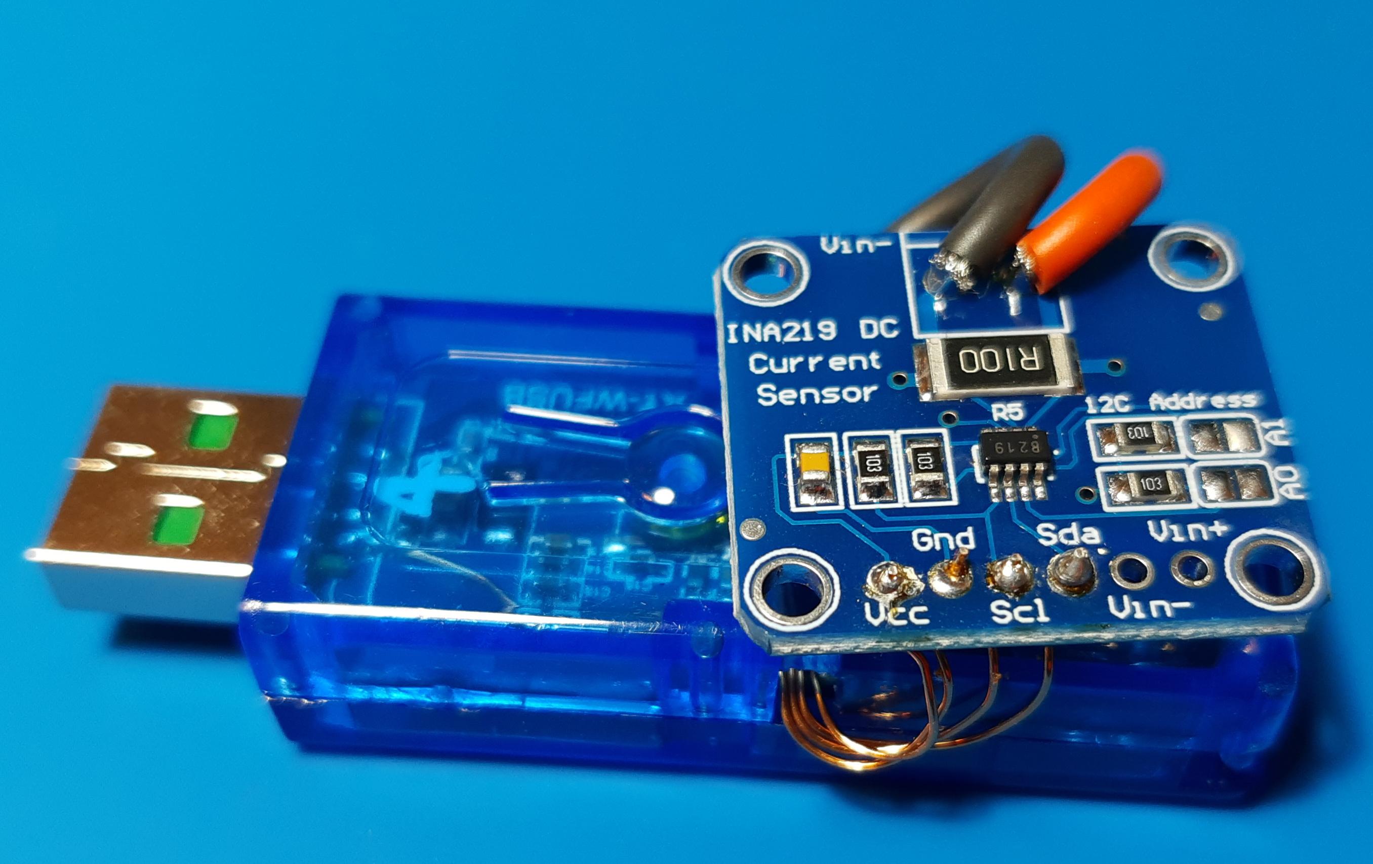
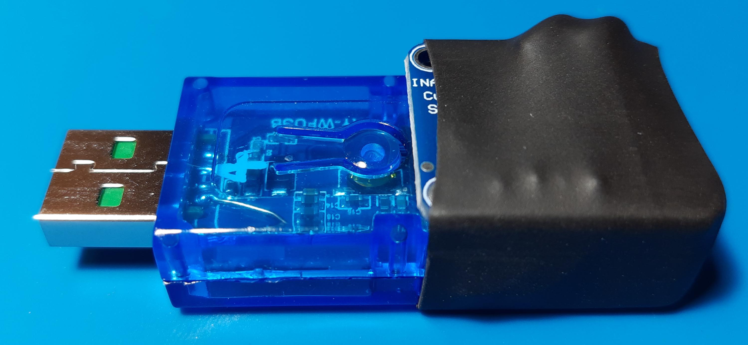
Cut some slots into the blue cover of the Sinilink device to pass through the cables you used.
Insert the cover between the Sinilink PCB and the INA219 module and bend the wires close to the case.
Use heat shrink tube around both modules.
Build Tasmota With INA219 Support
You need to compile Tasmota with INA219 support, the standard tasmota-sensors.bin, which contains INA219 support, is too large to fit into the ESP8285.
The following is a very brief explanation of the build process using docker, more details here.
Create a directory:
$ mkdir /opt/docker/tasmota-builder
Create docker-compose.yml
$ cat /opt/docker/tasmota-builder/docker-compose.yml
version: "3.7"
services:
    tasmota-builder:
        container_name: tasmota-builder
        hostname: tasmota-builder
        restart: "no"
        # source:  https://hub.docker.com/r/blakadder/docker-tasmota
        image: blakadder/docker-tasmota:latest
        user: "1000:1000"
        volumes:
            # docker container must be started by the same user who owns
            # the source code
            - ./tasmota_git:/tasmota
Clone git repository and switch to a specific tagged release of Tasmota:
/opt/docker/tasmota-builder $ git clone  https://github.com/arendst/Tasmota.git  tasmota_git
/opt/docker/tasmota-builder/tasmota_git (master) $ git checkout v8.5.1
Add an override file to include the INA219 support:
$ cat /opt/docker/tasmota-builder/tasmota_git/tasmota/user_config_override.h
#ifndef _USER_CONFIG_OVERRIDE_H_
#define _USER_CONFIG_OVERRIDE_H_
#warning **** user_config_override.h: Using Settings from this File ****
#ifndef USE_INA219
#define USE_INA219
#endif
Start the build:
"-e tasmota" means it's building only the tasmota.bin binary, nothing else.
/opt/docker/tasmota-builder $ docker-compose run tasmota-builder -e tasmota; docker-compose down
The resulting binary, tasmota.bin, will be located in:
/opt/docker/tasmota-builder/tasmota_git/build_output/firmware/
Setup the Sinilink device with Tasmota as explained by Andreas Spiess in his video. First flashing and then configuration of the template/usual GPIO setup for this device.
Either using your own compiled Tasmota binary or just use a standard release first, and then upgrade via webgui to your own compiled version.
Tasmota Configuration for INA219
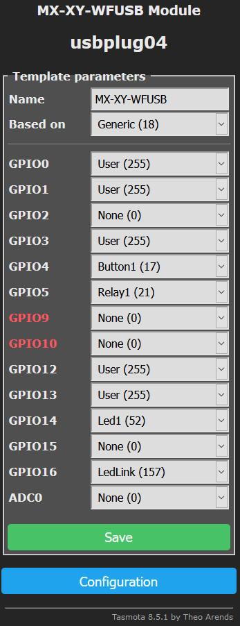
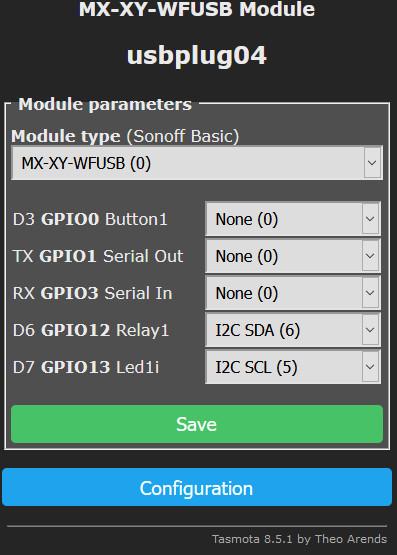
First step is to modify the template to match the modification.
Go to "Configuration" -> "Configure Template", select for GPIO12 and GPIO13 the "User (255)" value. Hit "Save".
After the reboot go to "Configuration" -> "Configure Template", select for GPIO12 -> "I2C SDA (6)" and for GPIO13 -> "I2C SCL (5)". Or swap those if you soldered the wires differently. Hit "Save".
Change the displayed/reported precision of the module. Change as you desire.
Go to "Console" and enter the following commands.
TelePeriod 30  # send MQTT sensor values every 30 seconds
VoltRes 3      # 3 digits precision on Voltage measurements
WattRes 3      # 3 digits precision on Watt calculations
AmpRes 3       # 3 digits precision on Current measurements
Final Result
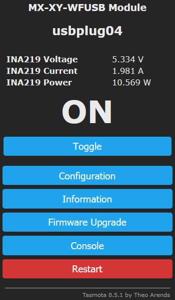
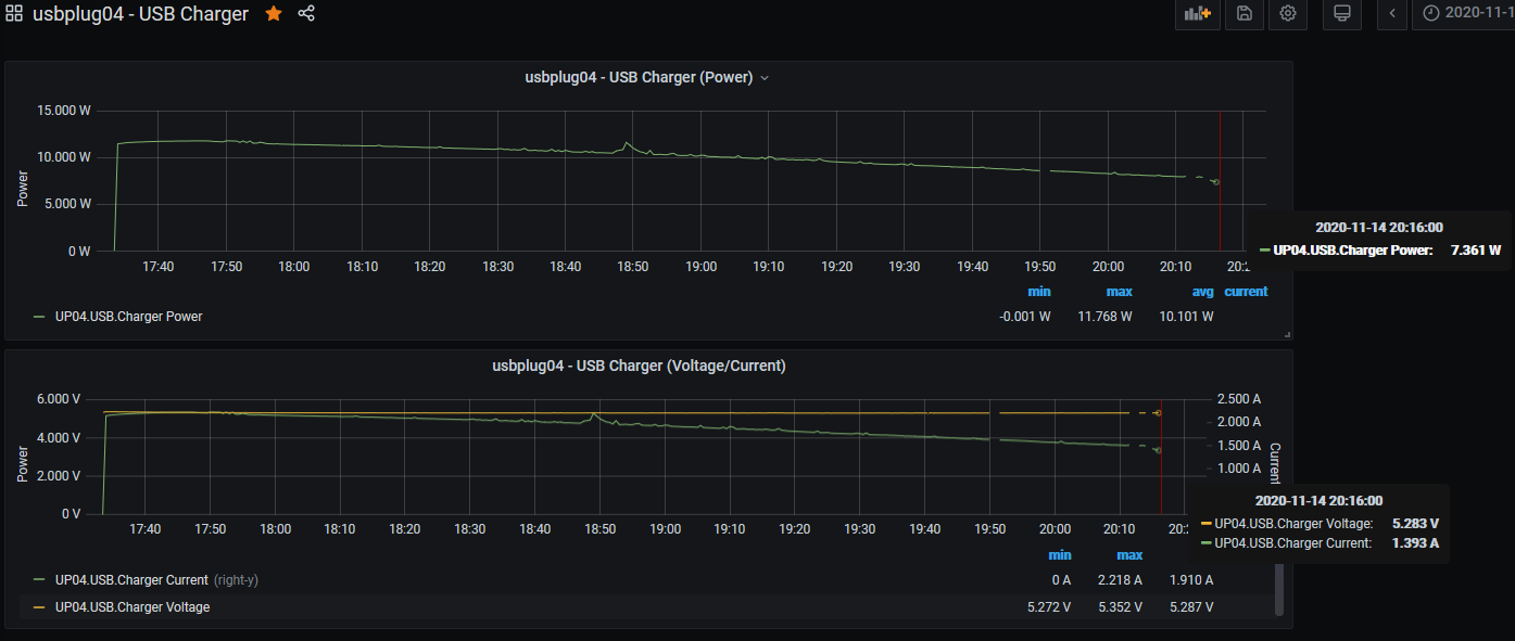
If everything was done correctly you can now monitor the Voltage and Current used by the attached USB device directly in the Tasmota Web GUI.
If you also have a setup for Tasmota to report the measurement via MQTT into an InfluxDB you can create graphs via Grafana to show charging current over time, here is an example of my smartphone charging from ~10% to ~85% capacity.
And following that setup you can use an automation tool like Node-RED to automatically turn off the USB switch when the current falls below a certain limit.
Be aware that since the INA219 uses a 0.1 Ohm resistor as a current shunt you'll get a voltage drop from the input to the output, depending on your power supply and the "intelligence" of the attached device it may charge slower than before.