Simplest Home Automation Using Bluetooth, Android Smartphone and Arduino.
by kksjunior in Circuits > Arduino
22451 Views, 253 Favorites, 0 Comments
Simplest Home Automation Using Bluetooth, Android Smartphone and Arduino.
Hello all,
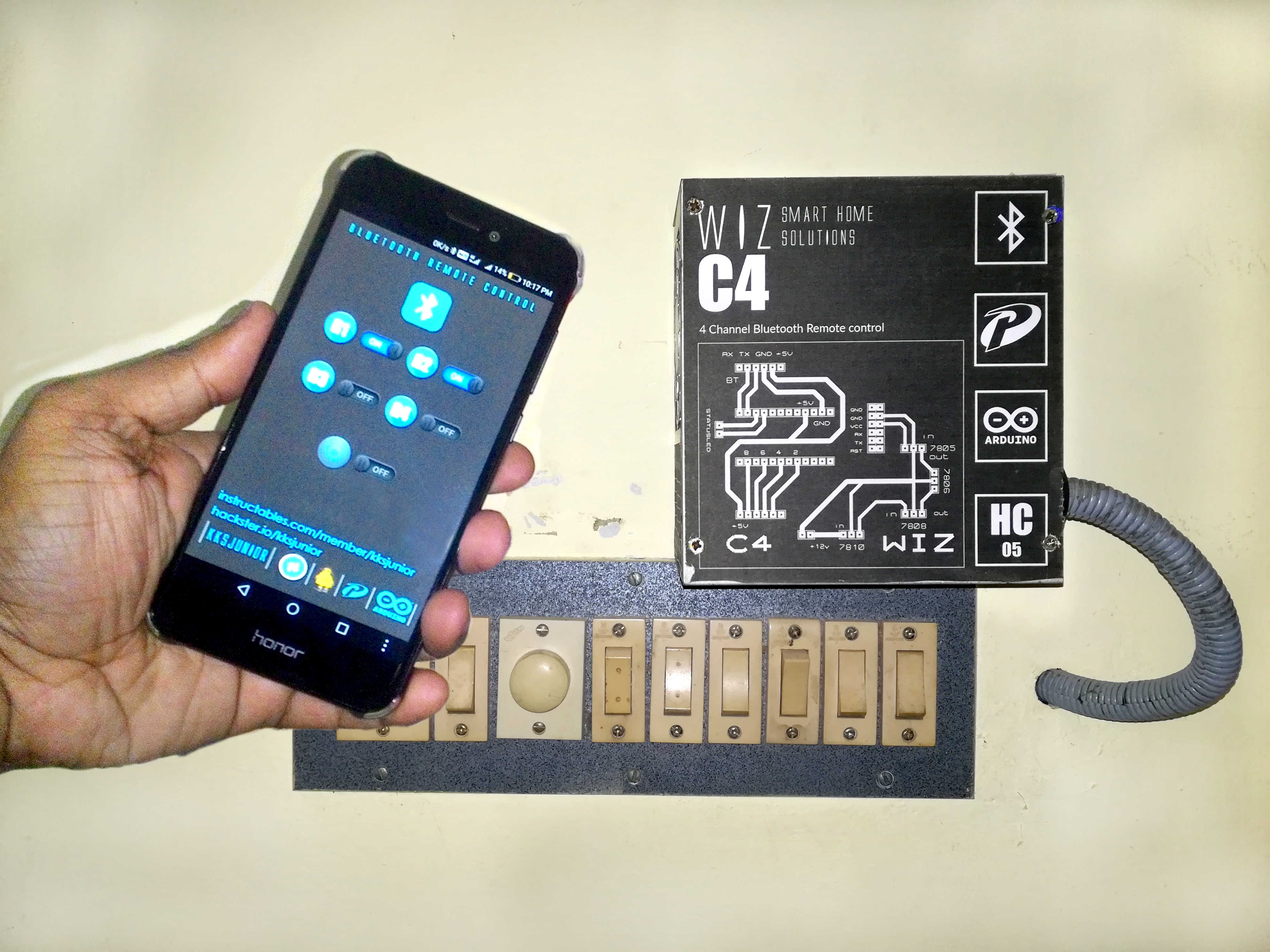
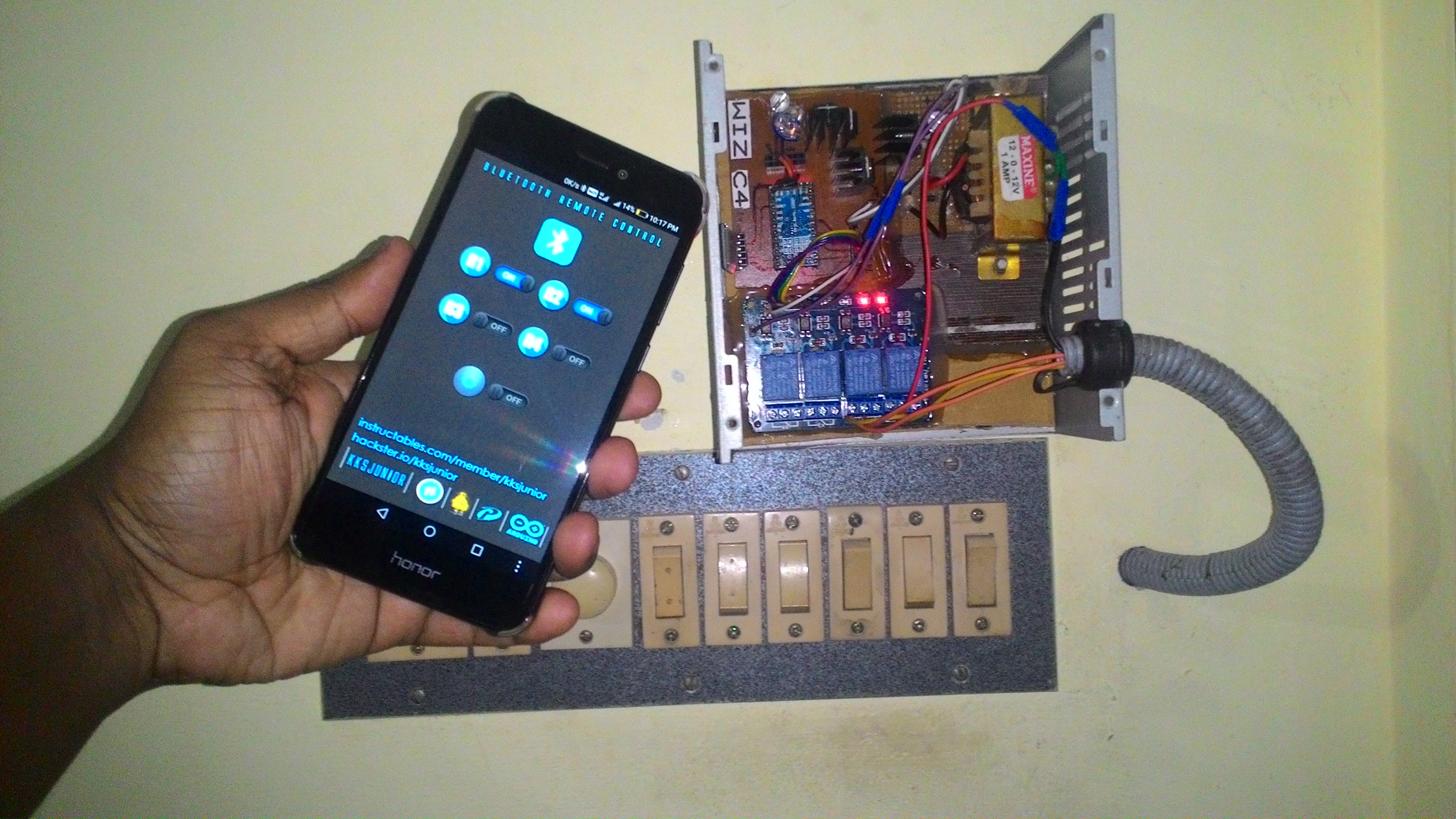
This project is all about building the most simplified home automation device using an arduino and a bluetooth module. This one is very easy to build and it can be built in a few hours. In my version which i'm explaining right here, i can control up to 4 home appliances using my Android smartphone. Let's have a look at the list of materials and tools you'll need.
Materials and Tools Required.
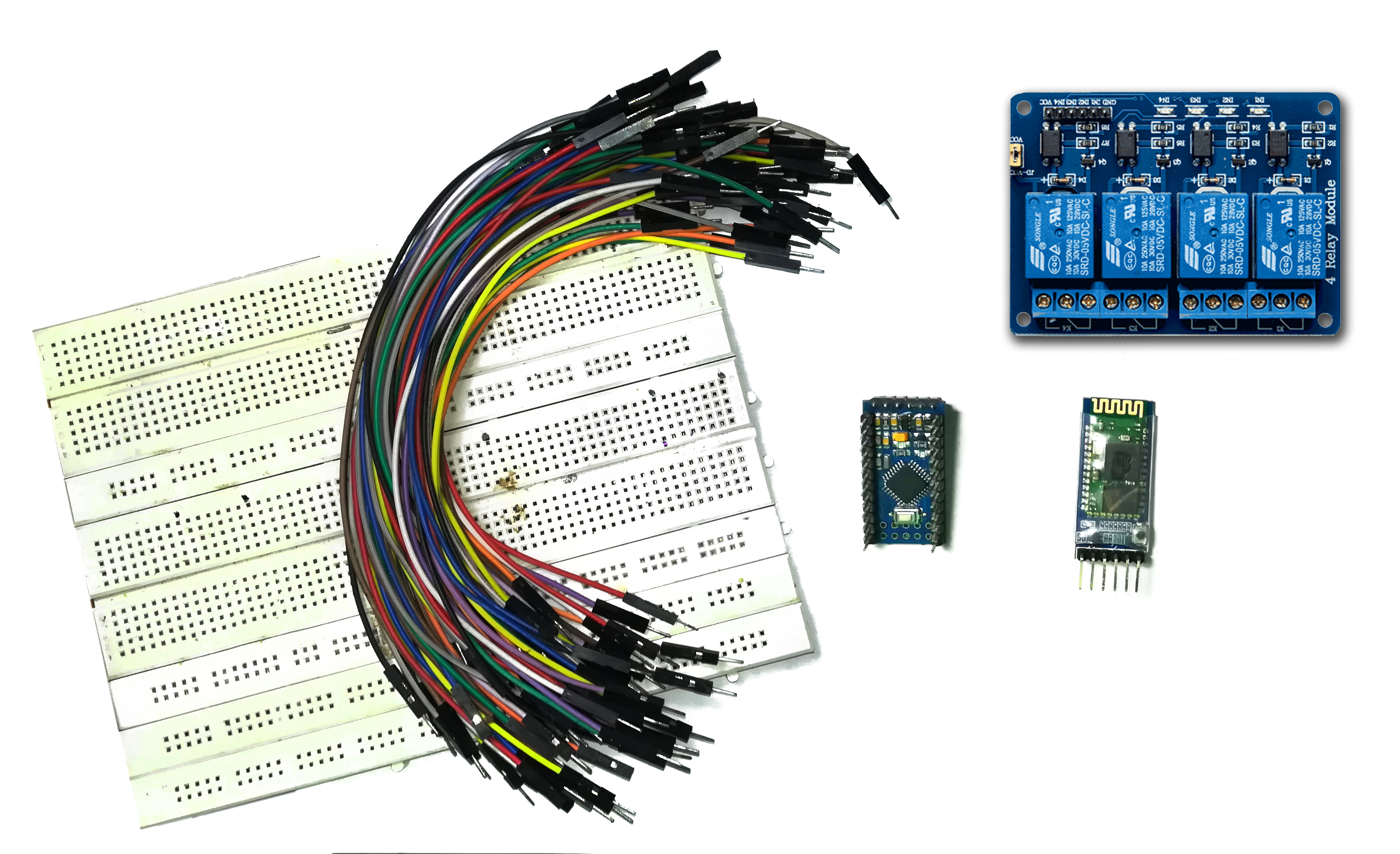
- 1. Arduino Pro Mini (Link to the store)
- 2. HC 05 Bluetooth module (Link to the store)
- 3. 5V 4 Channel Relay Module (Link to the store)
- 4. 5V power supply.
- 5. Male and Female headers
- 6. Perfboard ( i recommend making a PCB, but if you want to do it the easy way a perfboard is better)
List of Tools.
- 1. Soldering kit
- 2. Glue gun
- 3. Android Smartphone
- 4. Screwdrivers
- 5. Wire strippers etc:
That's all we need...
The Code
Download the Arduino IDE from here.
This code uses softwareserial.h to configure rx and tx pins in the Arduino. These rx and tx pins are connected to the tx and rx pins of the HC 05 Bluetooth module respectively.
The bluetooth module receives data from a paired android device and triggers the relays with respect to the data received.
For example, in my code if the received data is the character "A", the relay 1 will be triggered ON and if the received data is the character "B", the relay 1 will be turned OFF.
Similarly all the relays can be turned ON/OFF using bluetooth commands. Refer the code for detailed comments.
EEPROM
EEPROM is the acronym for Electronically Erasable Programmable Read Only Memory, which is used here to store the status of the relay (ON/OFF), so that in case of a power failure when the controller resets, all the relays which were kept ON will come back to their ON position after the power has come up. So whenever a relay is turned on, a variable stored in an address in the EEPROM changes it's value to 1 and whenever it's turned OFF the same variable changes to 0. Each relay has it's own variable assigned to store it's status in the EEPROM. So at the beginning of the code the first thing we did was to initialize the relays according to the values stored in the EEPROM.
If you're using an Arduino Pro mini you'll need a USB to TTL converter to dump the code in to the Arduino.
Downloads
The Android Application
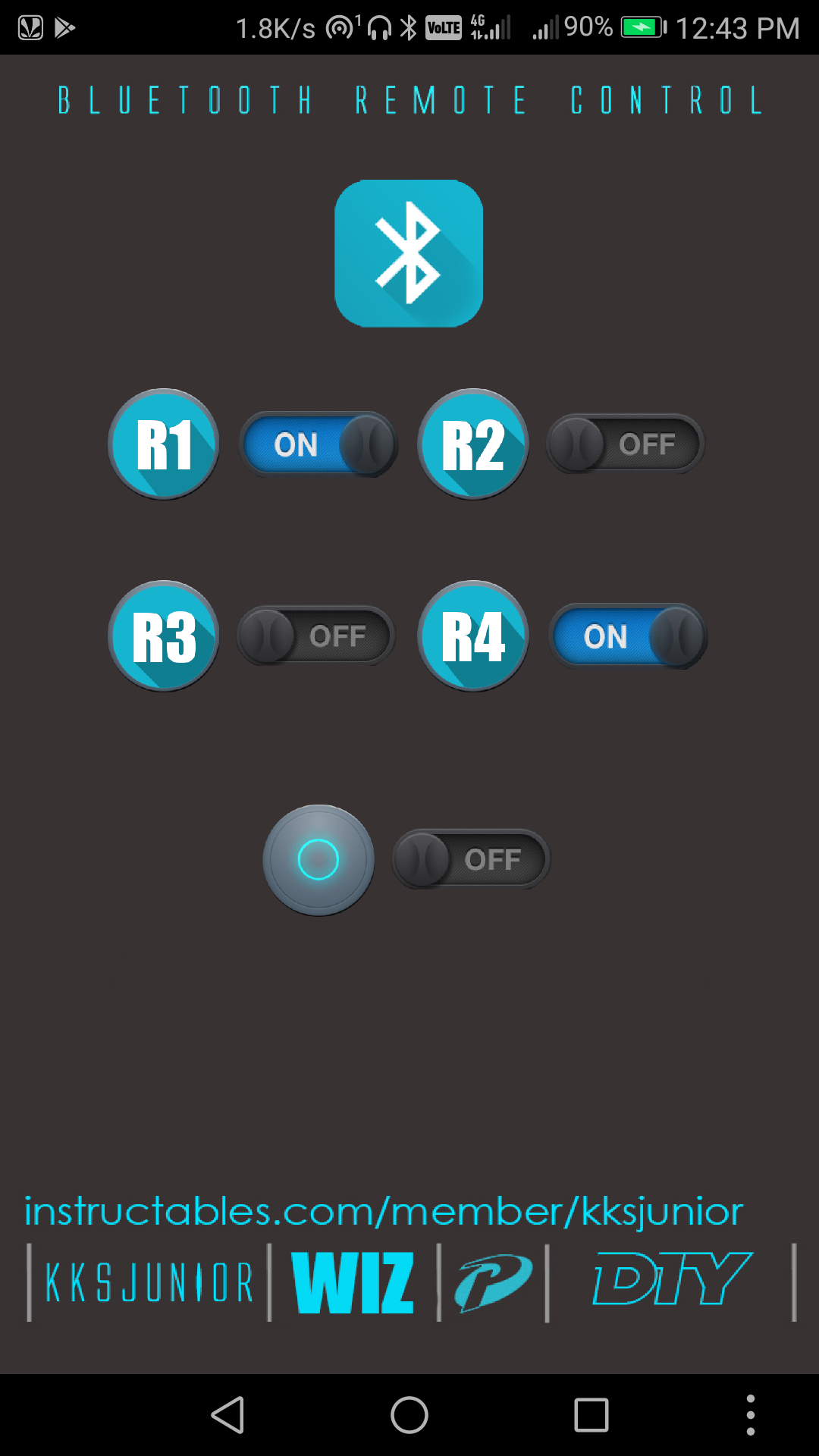
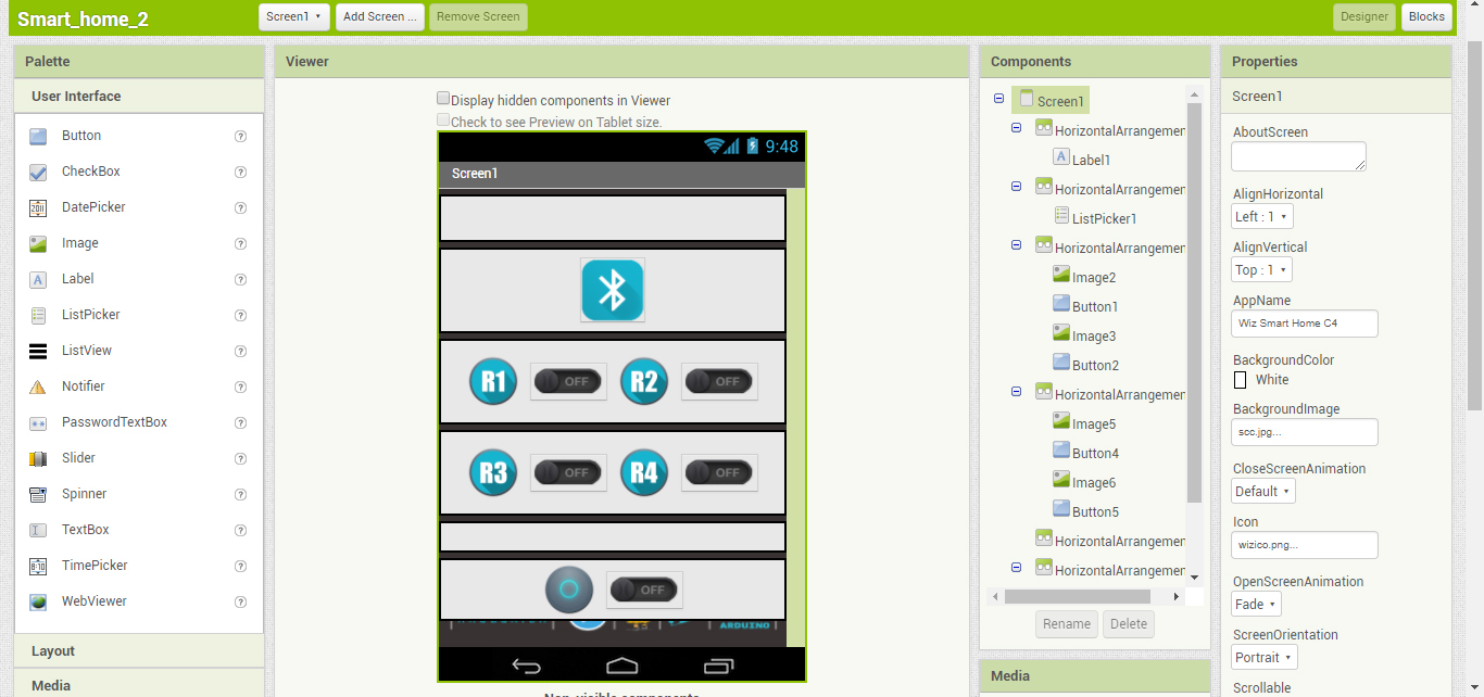
As mentioned above, the micro-controller triggers each relay according to the data it receives through the Bluetooth Module from an Android device. So we need an Android application to send these data to the HC 05.
I made a customized application using the MIT App inventor. I've attached the 'blocks layout' of my application as a PDF here for reference for those who are going to make their own app using the App Inventor.
If you don't want to bother making the app, you can just download the ready to use App (Only compatible with the code I've attached above) from the link below.
Instructions for the Android App
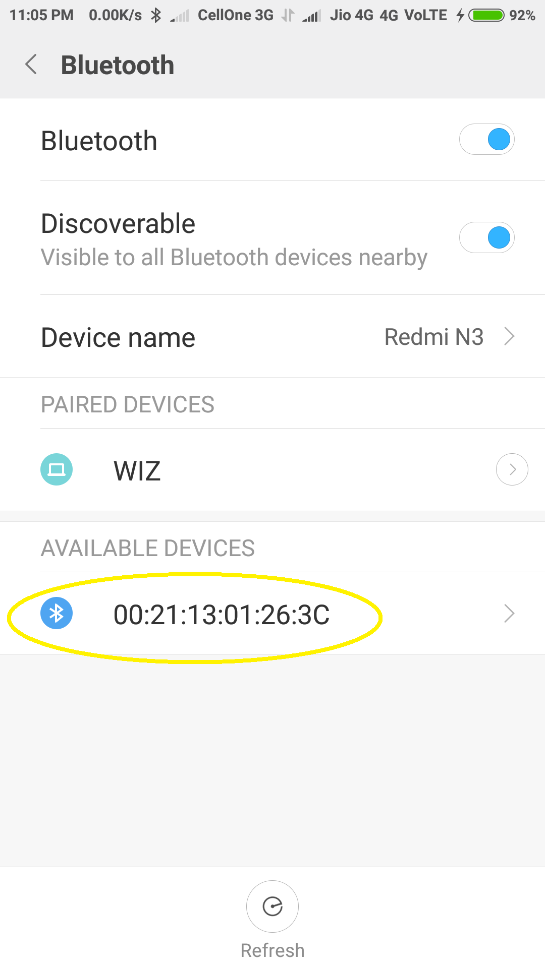
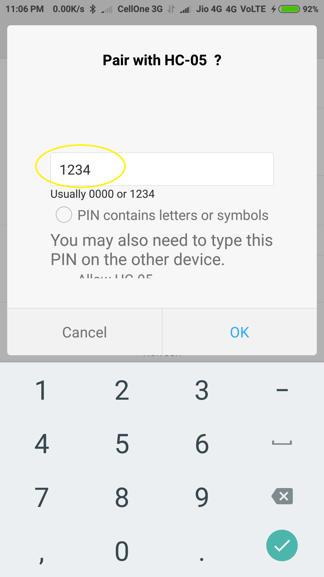
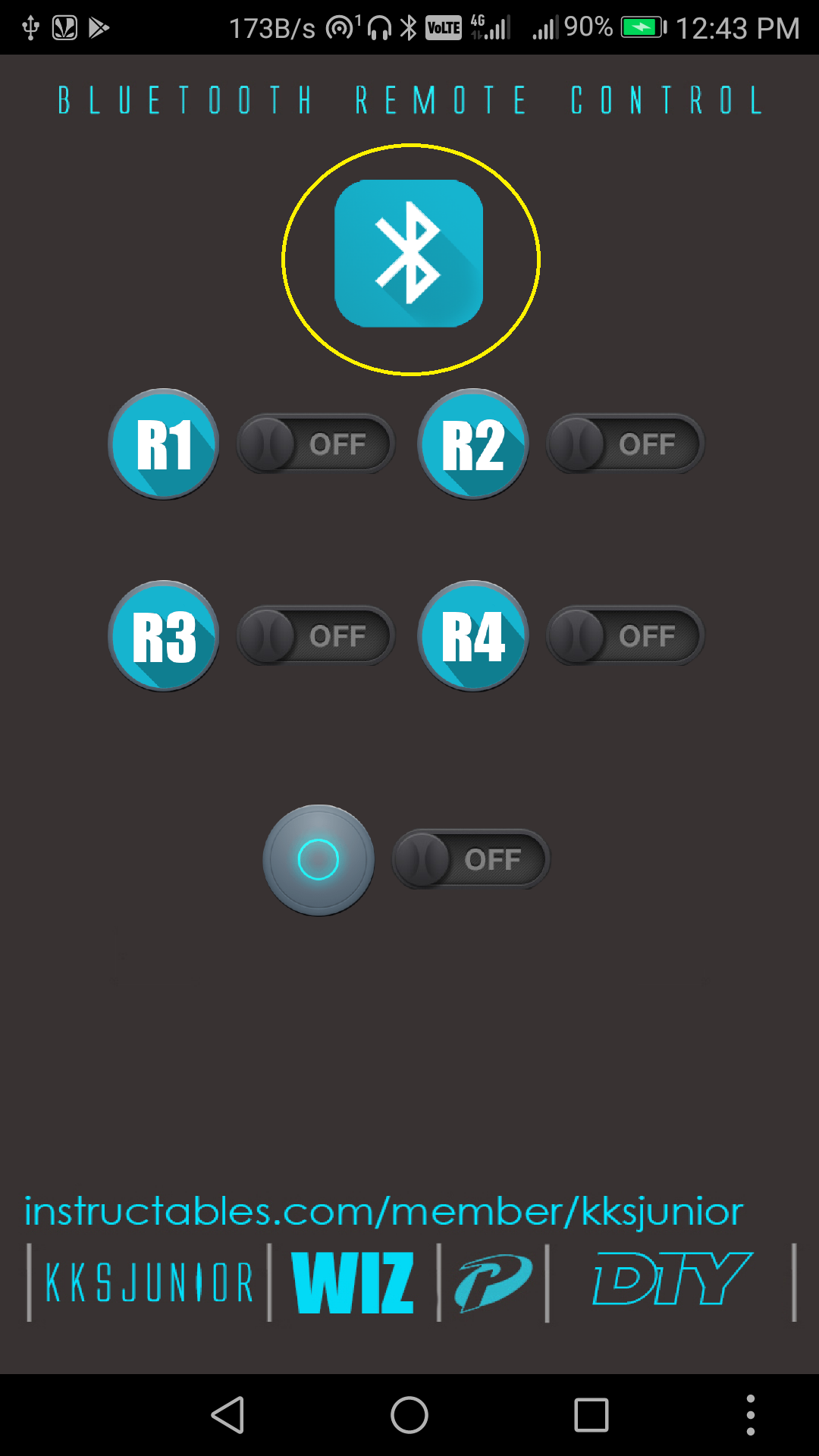
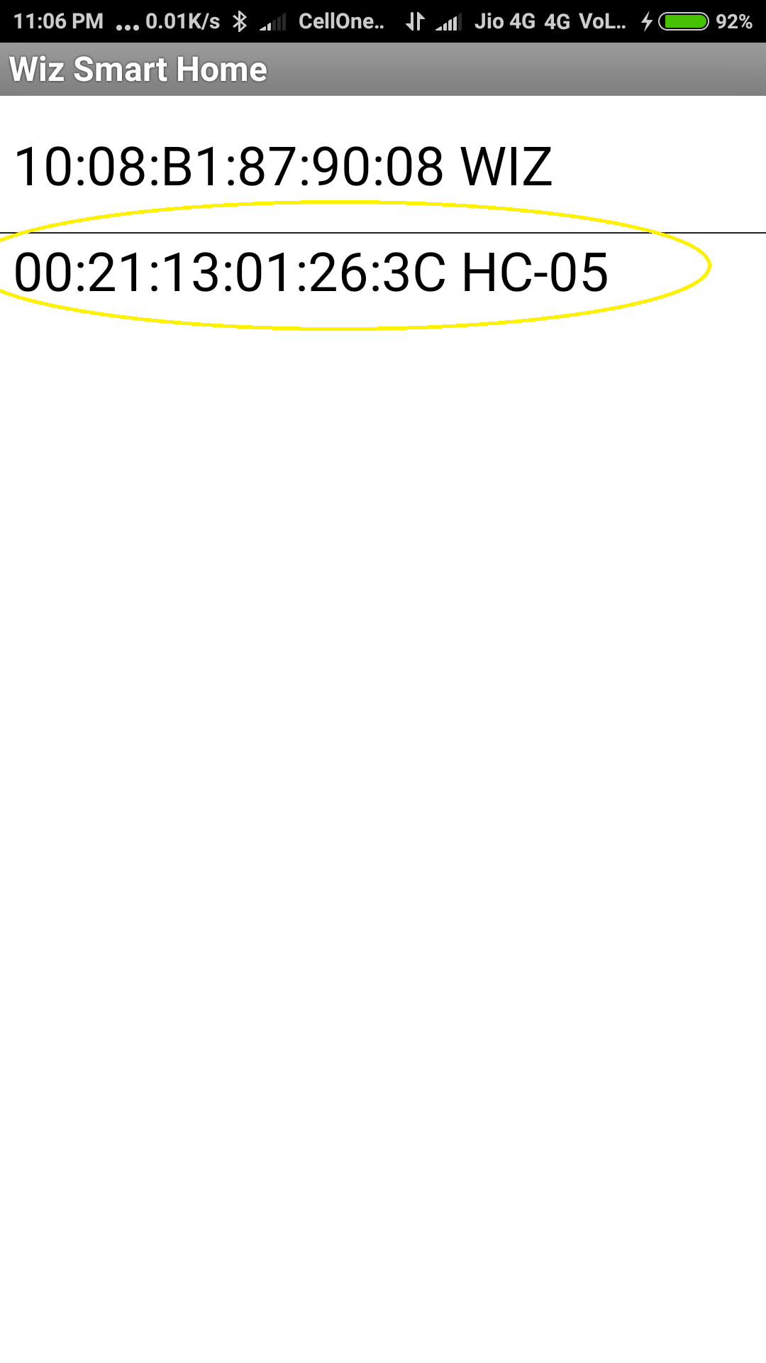
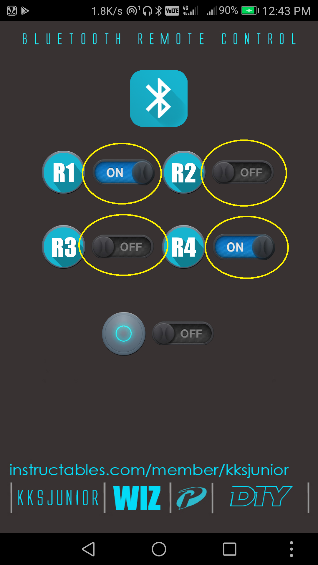
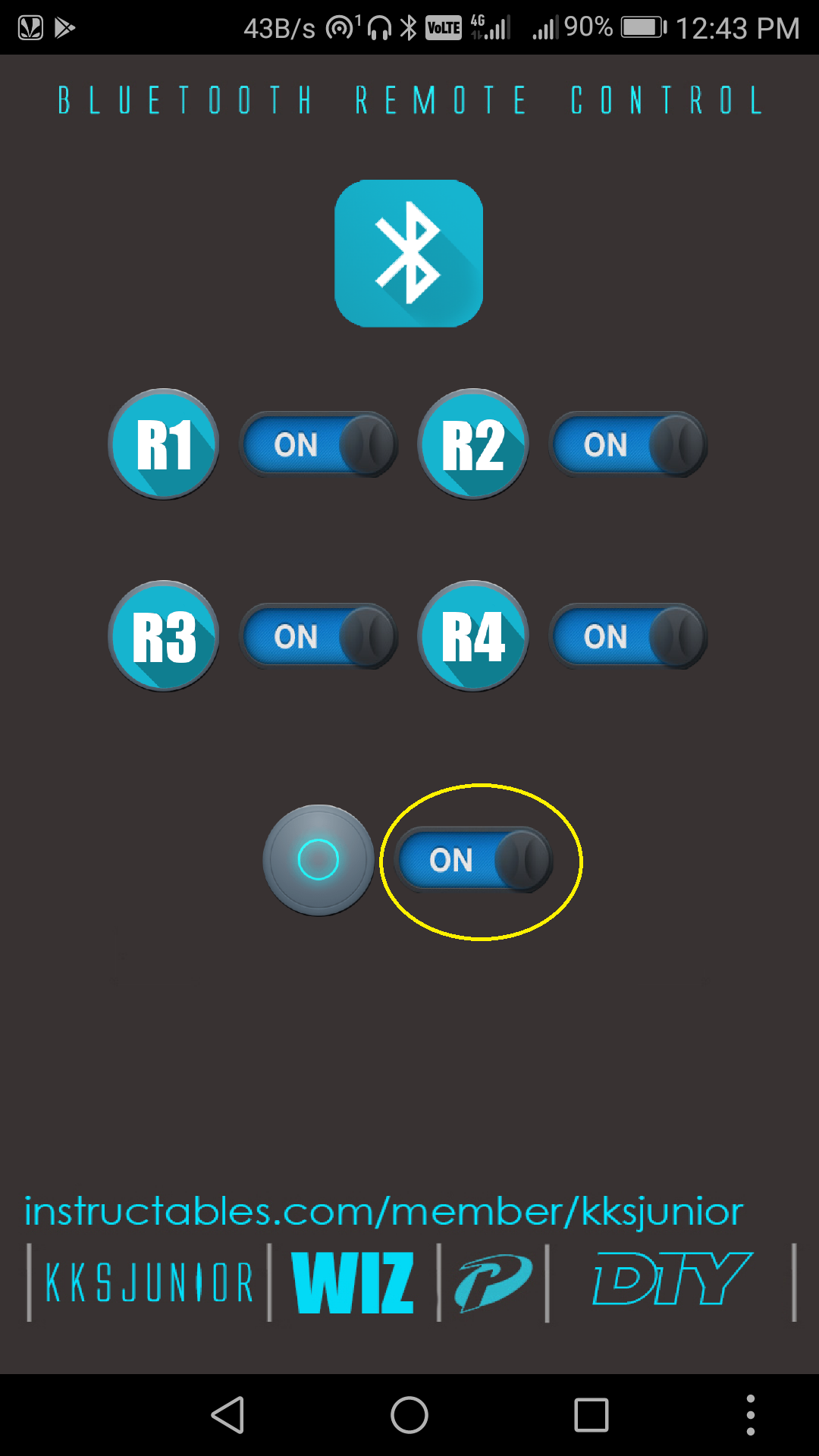
You have to pair the HC-05 Bluetooth module to your android device before you could use it in the app.
Step 1 : Open your device's bluetooth settings and search for new devices, make sure the led on HC05 module is blinking continuously (Pairing Mode).
Step 2 : Select HC 05 ( or you'll see an address ending with "C" as shown in the picture.)
Step 3 : Enter the PIN "1234" and press OK.
Step 4 : Open the "Wiz Smart Home" app and click the bluetooth button on the top of the screen.
Step 5 : Select "HC 05" from the list.
Step 6 : Use the respective switches to turn ON/OFF the relays 1,2,3,4.
Step 7 : Click the Master to turn all the relays ON/OFF in a single click.
Circuit.
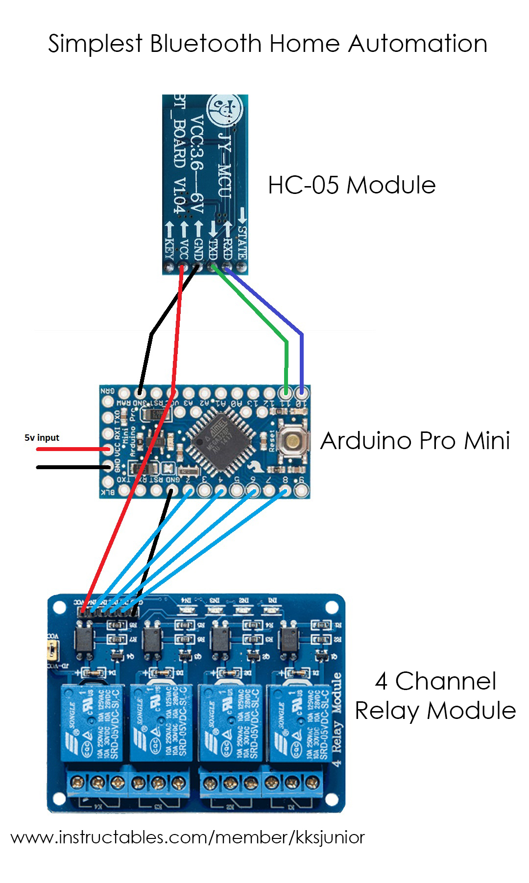
- Pin 11 of Arduino to TX Pin of HC-05 Module.
- Pin 10 of Arduino to RX Pin of HC-05 Module.
- GND of HC-05 to GND in Arduino.
- Vcc of HC-05 to Vcc (5v) in Arduino.
- Vcc of Relay Module to Vcc (5v) in Arduino.
- GND of Relay Module to GND in Arduino.
- Pin 2 of Arduino to R1 of Relay Module.
- Pin 4 of Arduino to R2 of Relay Module.
- Pin 6 of Arduino to R3 of Relay Module.
- Pin 8 of Arduino to R4 of Relay Module.
- Give 5-v power supply to the power pins of Arduino.
- Pin 12 and 13 are the Pins for the Power indication and the Bluetooth Status Indication LEDs respectively
That's it for the device.
In-order to control the mains, connect the "Normally Open" contacts of each relay across the respective switches of the home appliances you'd wish to control (or) loop the live wire through one contact of "NO" of all the relays and connect the leads of the appliances to the other contact of "NO" of their respective relays.
Downloads
PCB Design
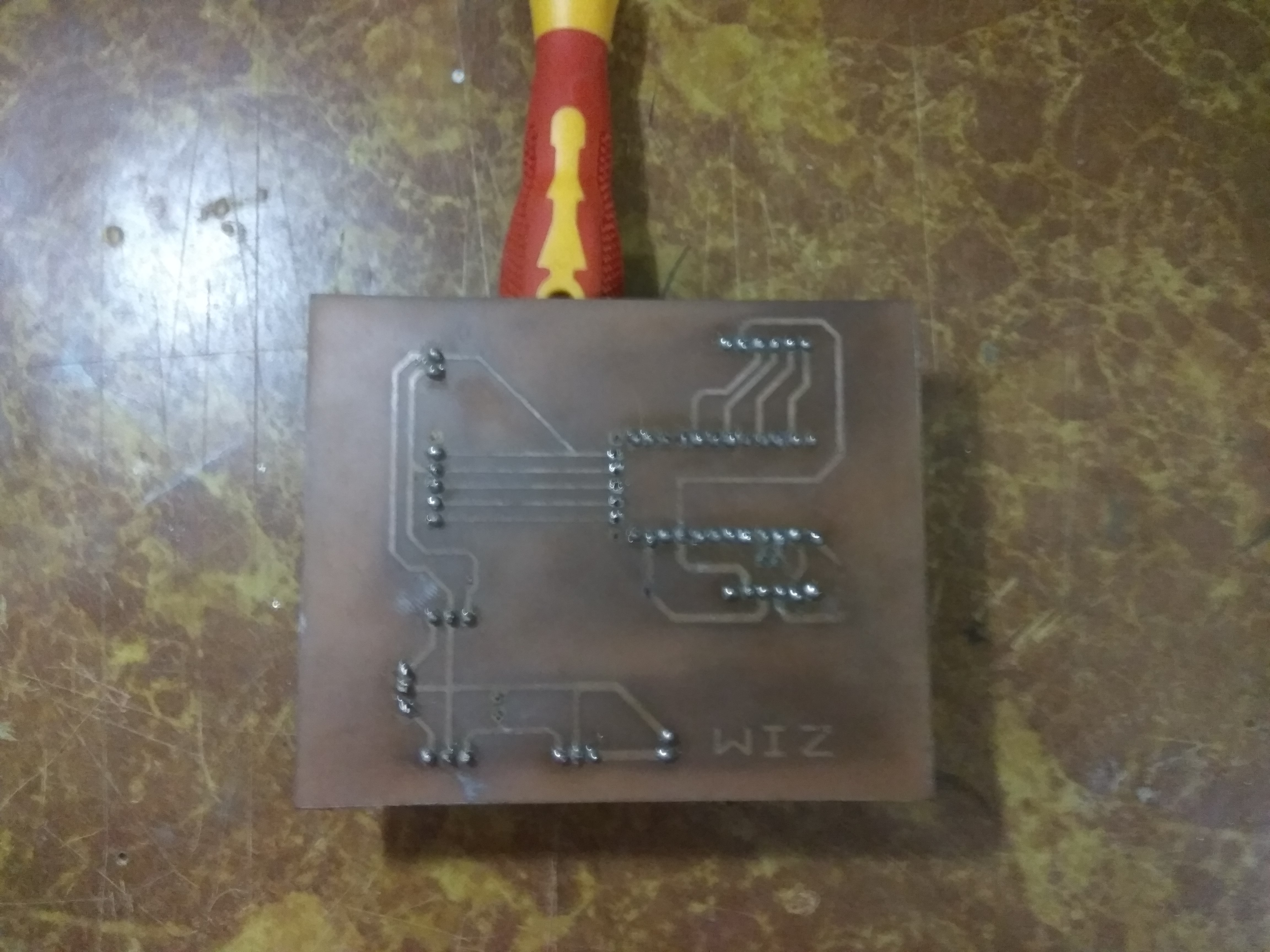
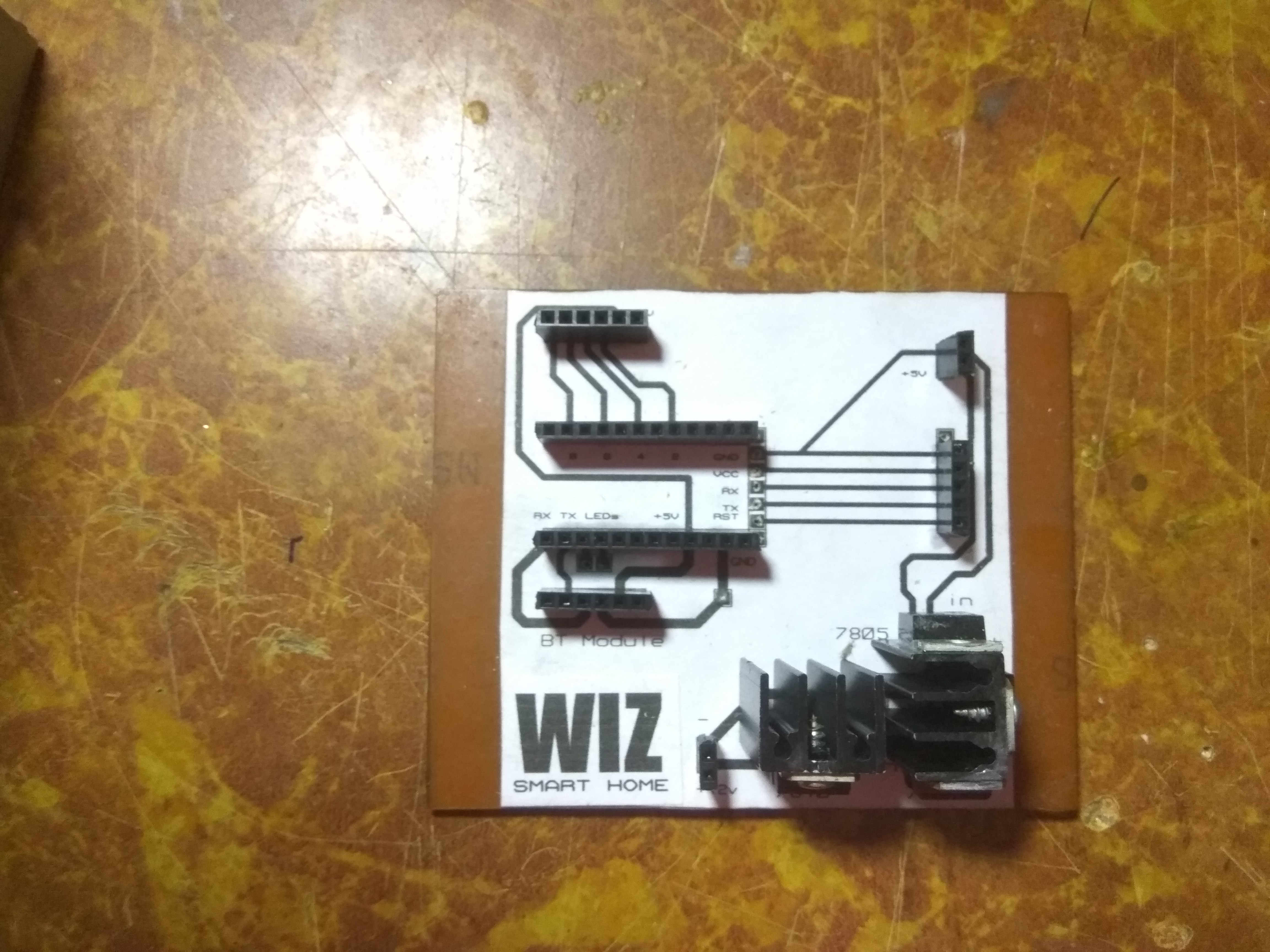
This is a very simple circuit. You can solder it on a perfboard in no time, but if you still wish to make a PCB, i'm attaching the PCB Design which I've made using Proteus 8 Pro. My version also had a series of voltage regulators as shown in the pictures.
Assembling the Components.
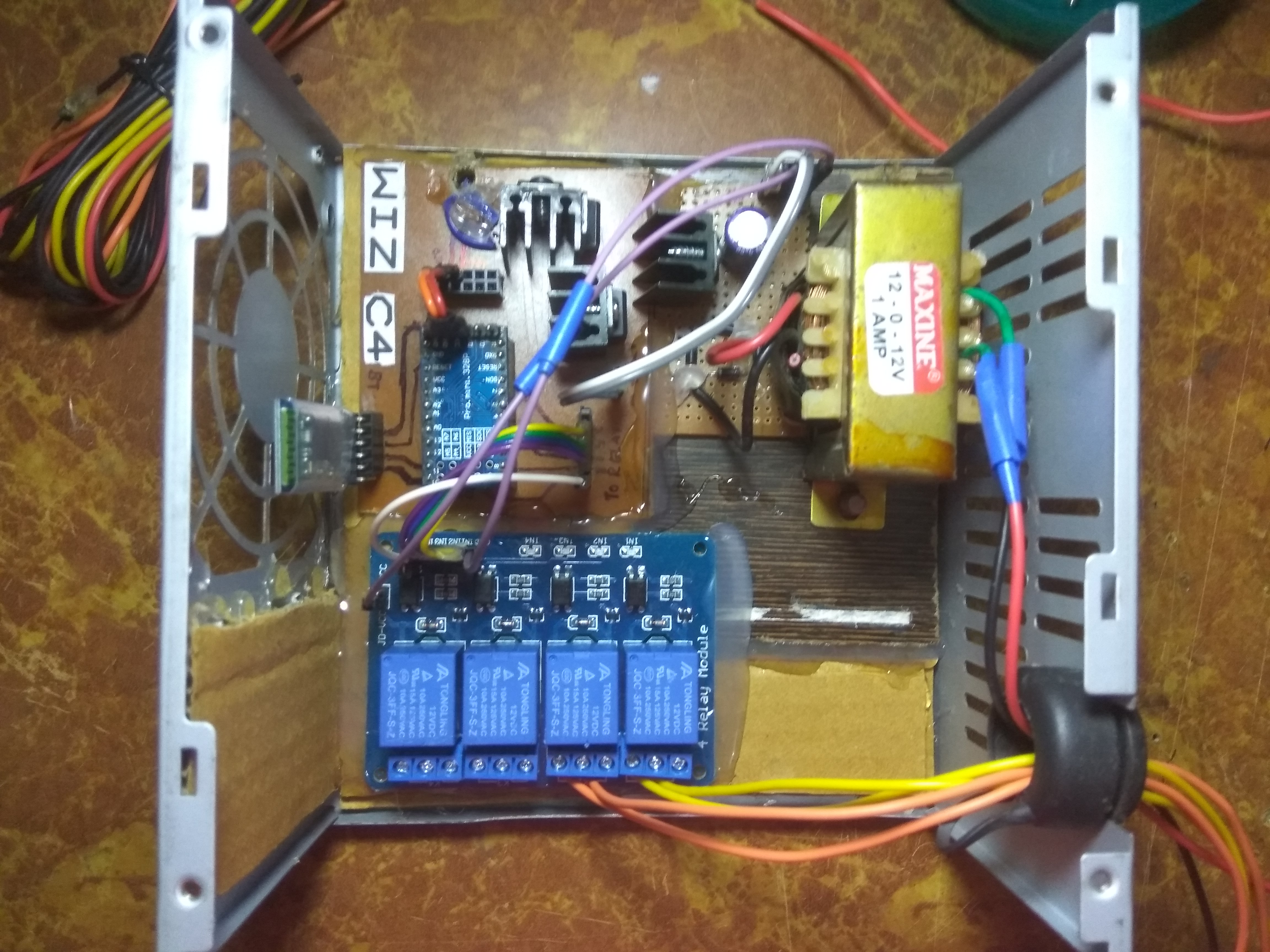
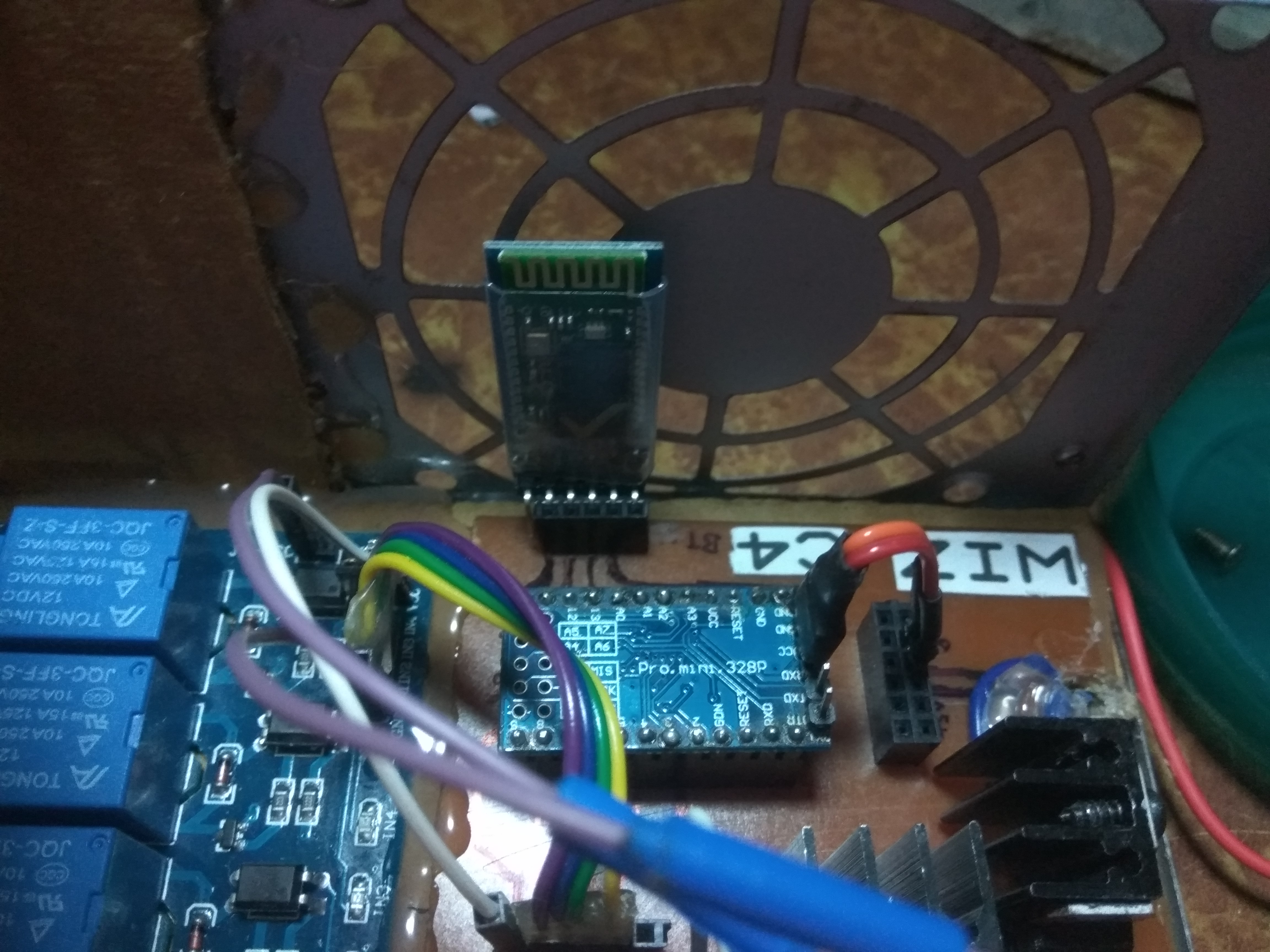
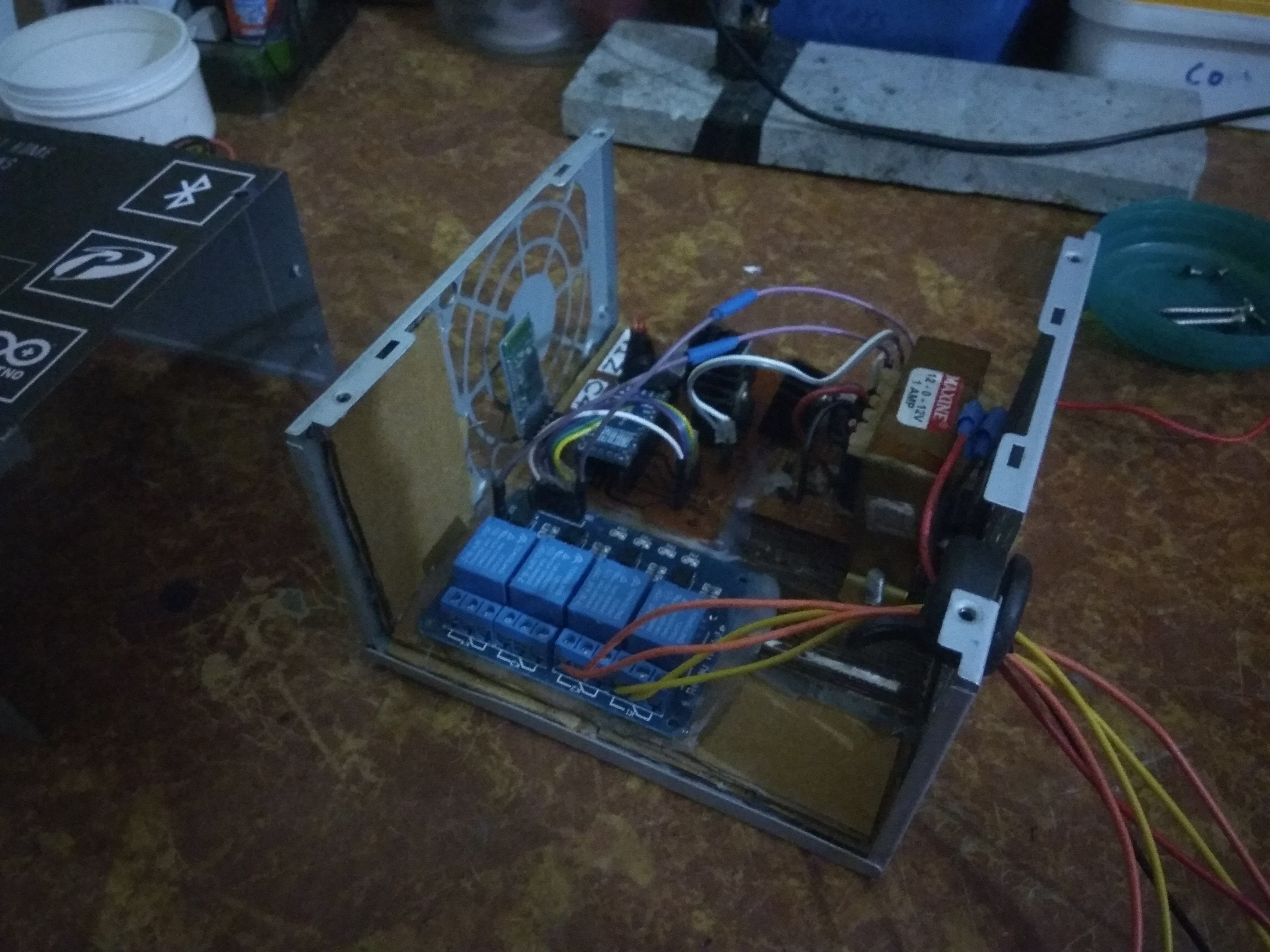
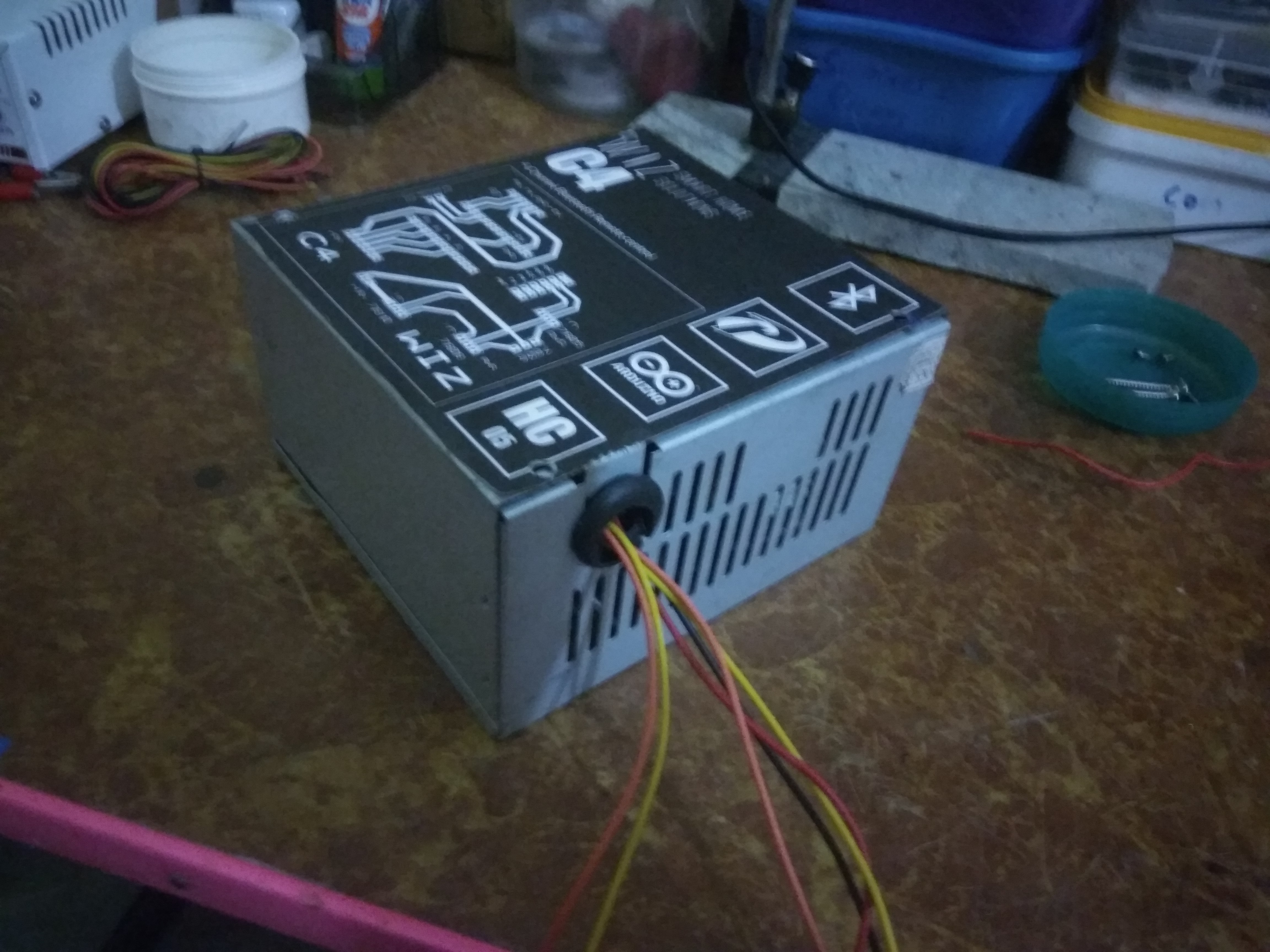
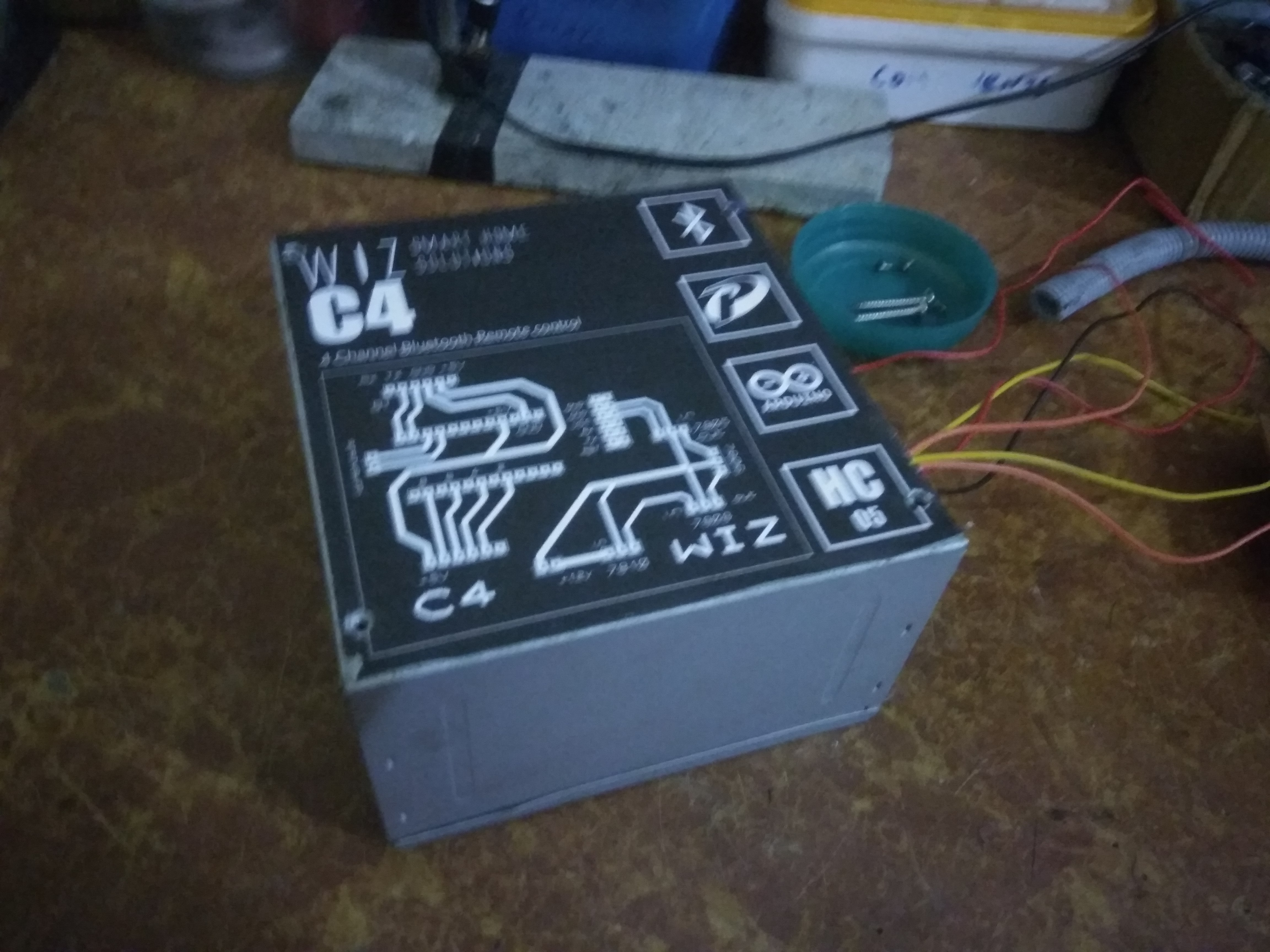
I used the enclosure of an old computer SMPS to make the case for my device. It'll be better to design a custom case according to your needs using Fusion 360 or any other 3D design software and 3D print the design to give your project a super-cool look. I printed some labels and pasted it on the SMPS enclosure to fill the empty look of it. I drilled some holes in it and fixed it on the wall next to the switch board.The wires were hidden using a small plastic pipe leading in to the switchboard.
The Result.

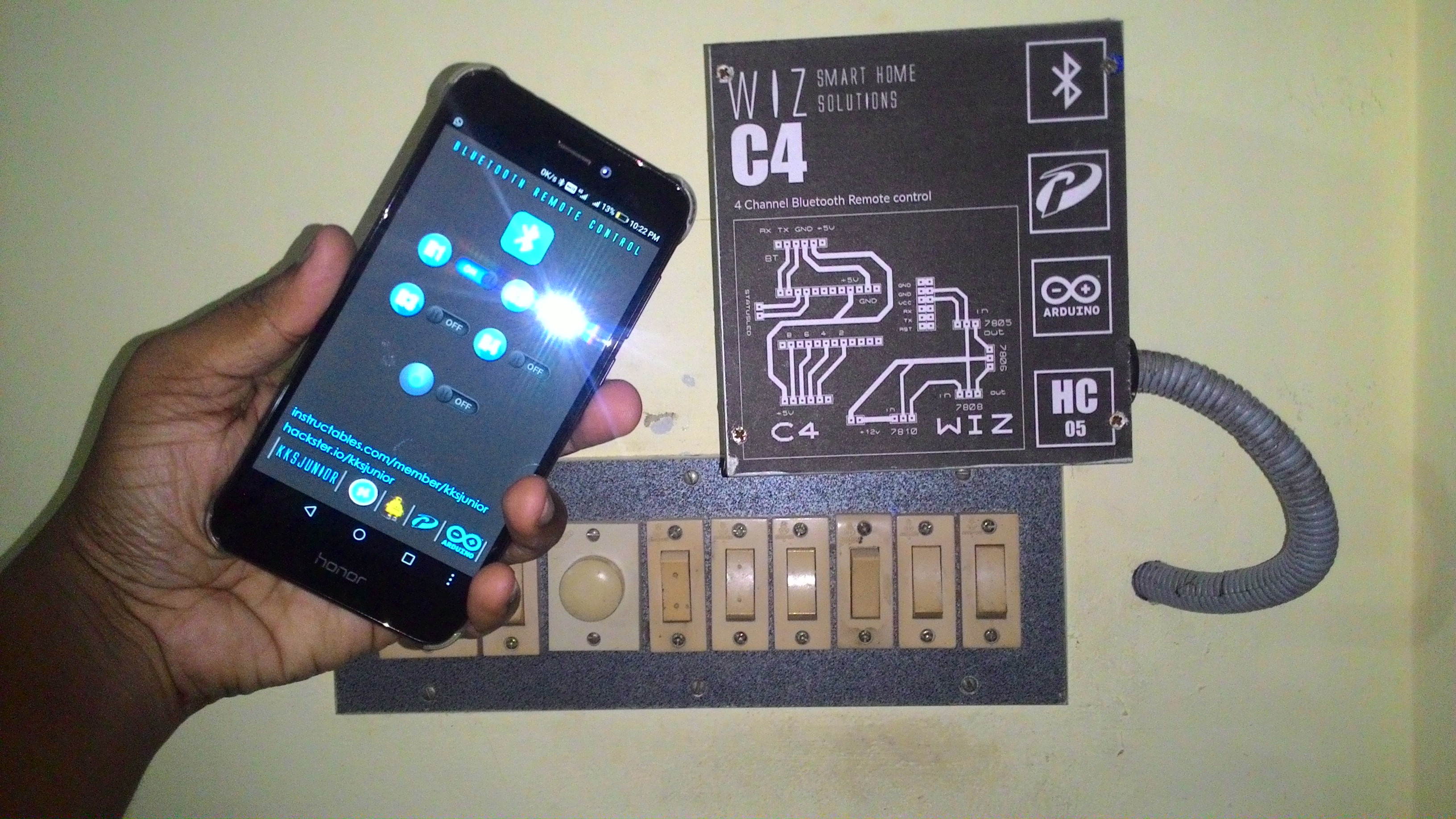
The video posted here shows the working of the device when you use it for the first time. You only need to pair the device once! After that, just turn on the Bluetooth, connect and go wireless!
Hope you enjoyed reading this instructable. If you've any questions, feel free to ask it here or send a mail to dream.code.make@gmail.com. I'll be happy to help you out.
Thank You...!!! :)