Simple Wheel and Wheel Cover Design With Solidworks for 3D Printing
by jbarv in Workshop > 3D Printing
814 Views, 0 Favorites, 0 Comments
Simple Wheel and Wheel Cover Design With Solidworks for 3D Printing
This is an easy way to make a wheel and an aerodynamic cover for it using solidworks and 3d printing. Whether you want to use the cover on a model, RC car, or just print it for fun, it is a great way for beginners in CAD and 3D printing to combine their hobby with a passion for cars.
Supplies
Solidworks, and a 3D printer, I use an Elegoo Neptune, and attached the PLA I used.
https://www.amazon.com/OVERTURE-Filament-Consumables-Dimensional-Accuracy/dp/B07PGZNM34/ref=sxts_rp_s_a_1_0?content-id=amzn1.sym.3432eb1a-1558-4445-9430-9bb3e7f7b9b7%3Aamzn1.sym.3432eb1a-1558-4445-9430-9bb3e7f7b9b7&crid=GSTSLVV2WZB&cv_ct_cx=pla&keywords=pla&pd_rd_i=B07PGZNM34&pd_rd_r=8c1864b8-7de4-4676-a3e8-f036e7500b1a&pd_rd_w=2tGS6&pd_rd_wg=lclqa&pf_rd_p=3432eb1a-1558-4445-9430-9bb3e7f7b9b7&pf_rd_r=35E0JHB07TMDZ7QP28ST&qid=1682032217&sbo=RZvfv%2F%2FHxDF%2BO5021pAnSA%3D%3D&sprefix=pla%2Caps%2C112&sr=1-1-5985efba-8948-4f09-9122-d605505c9d1e
2D Wheel Shape
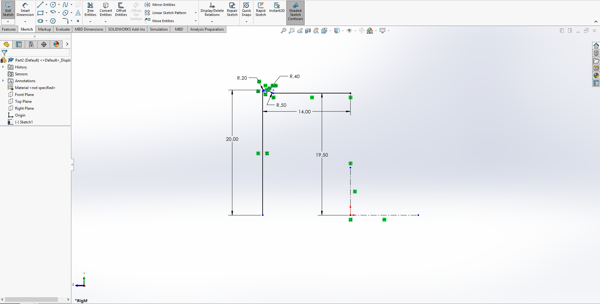
When revolving drawings, I prefer to begin on the right plane to keep the faces of my part on the front plane. Something similar to this sketch is what you want to recreate. We need the two construction lines so we can mirror around the vertical one, and extrude around the horizontal. The measurements are based off the size you're looking for. Keep in mind, the height of the outer lip, as well as the height of the inner edge, are going to be smaller than the opening for the spokes.
Mirror
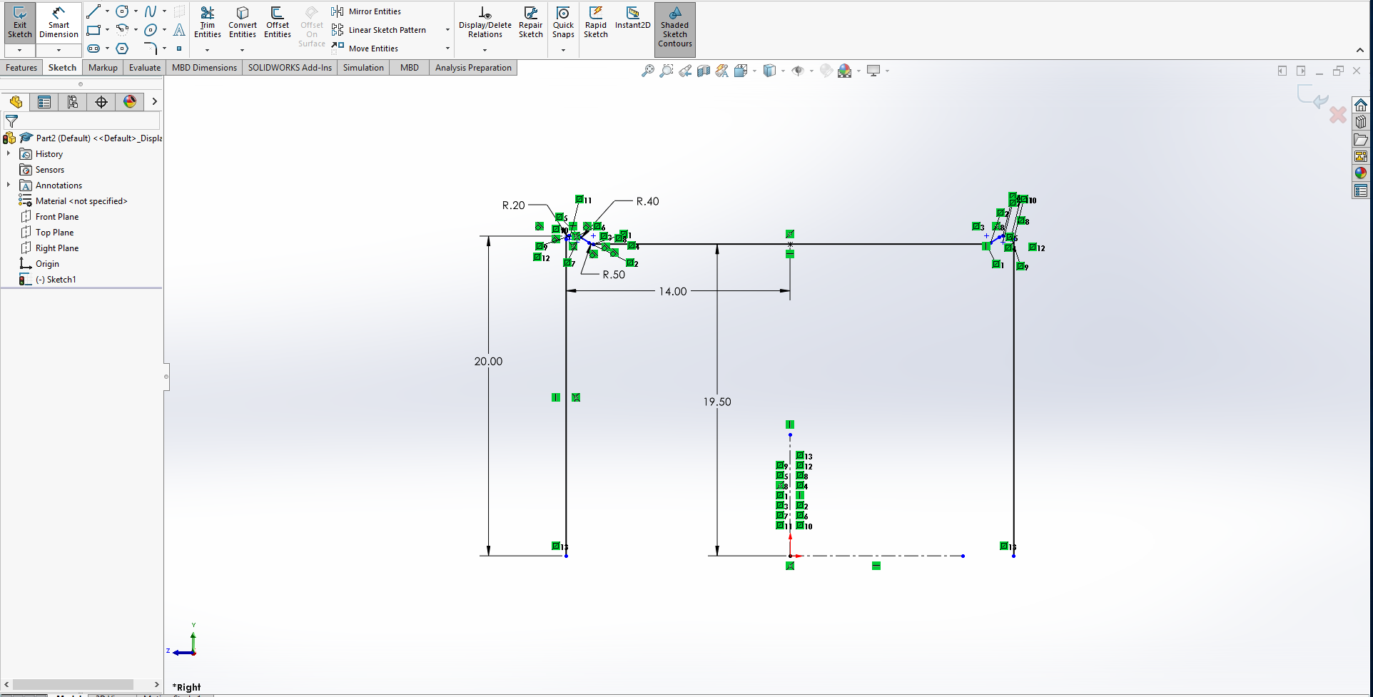
Using the mirror command, we can copy over our sketch to have a symmetrical outline. Time to extrude.
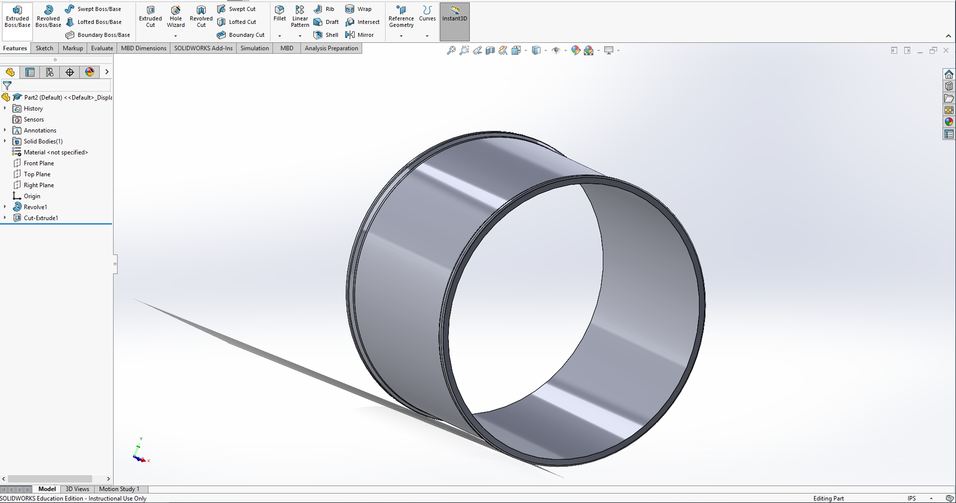
Extrude
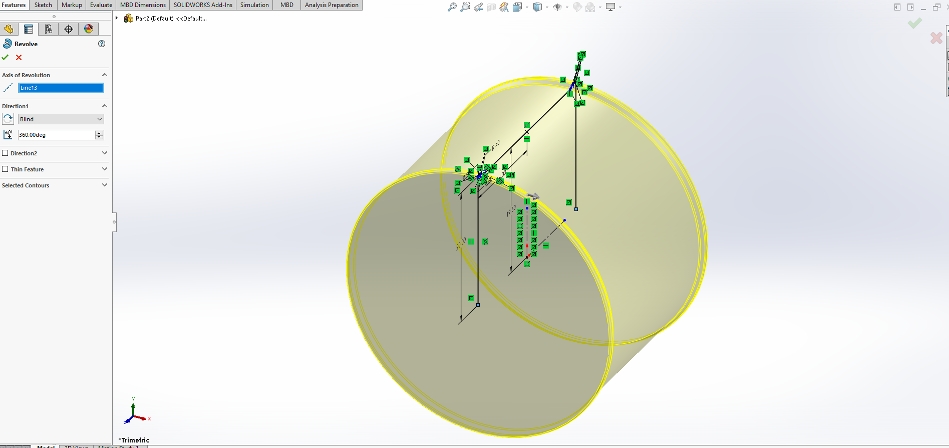
Using our horizontal construction line, we will do a revolved boss to make a wheel shape out of our drawing. If Solidworks tells you it needs to close the drawing, select okay, you will get the same result.
Cutting Out the Middle
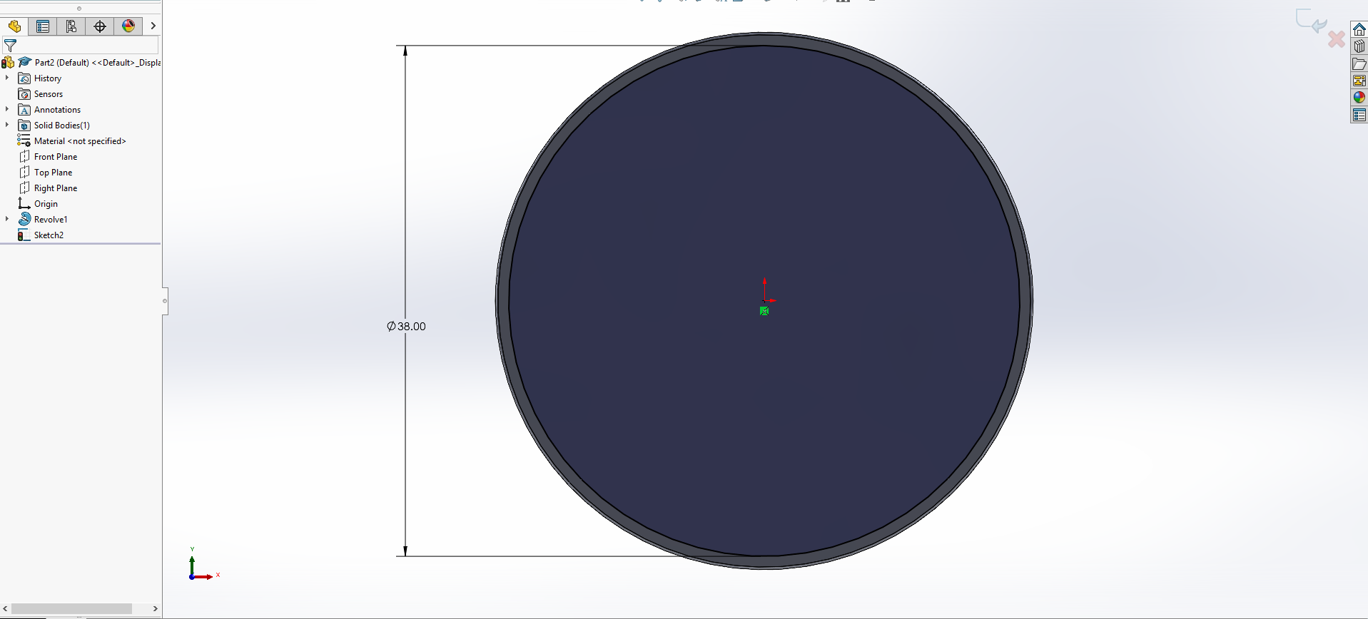
Next, we will select the face of our revolved wheel, so we can cut out the center. Keep in mind you will have to make the radius of your cut slightly smaller than the radius on your original sketch, otherwise there will be no structural integrity.
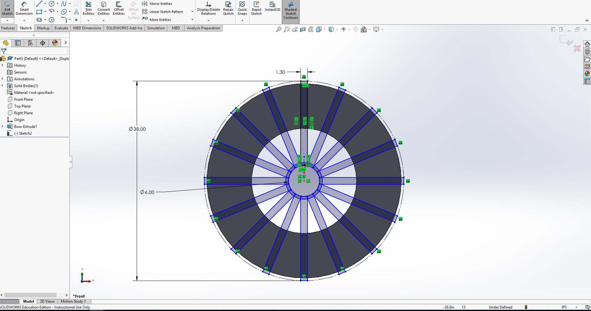
Making Spokes
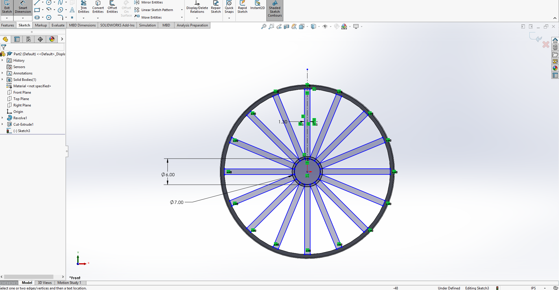
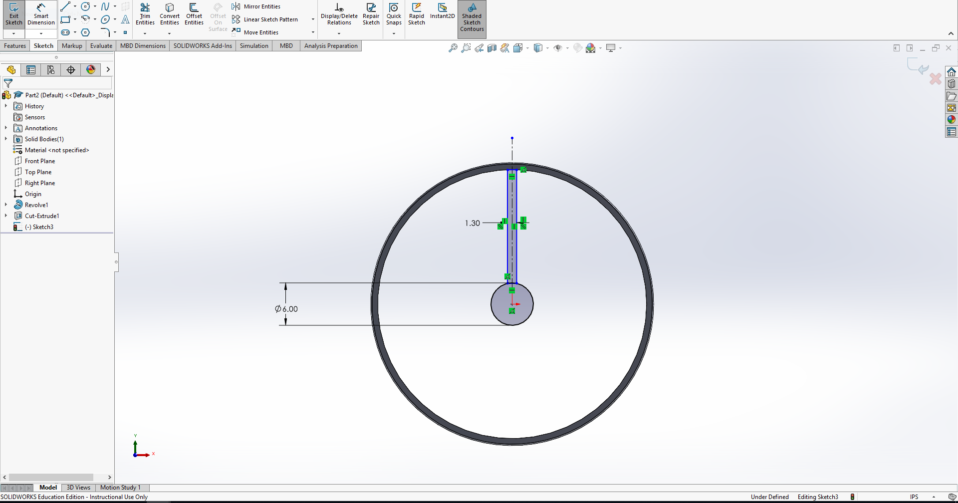
This is a relatively simple example of the spokes, but you can do it in anyway you'd like to. The steps will be the same. No matter what design you're going to use, we start by making a small circle, followed by a slightly larger circle. This allows us to create the hole in the center for the axle, but also giving our spokes a place to connect. Once you have a spoke design you like, use the circular pattern feature to copy the spoke around the center of your wheel.
Take note of the measurements of your spoke, as these will be important later.
Extruding Spokes
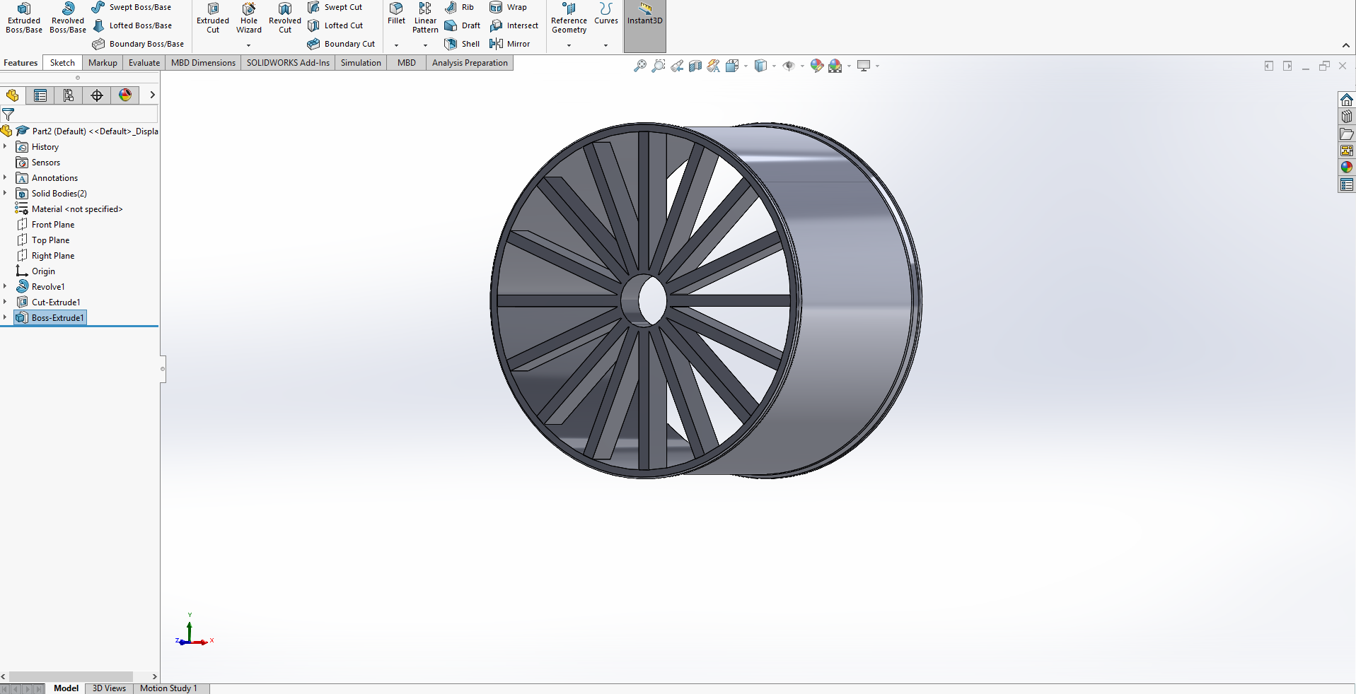
Using the Boss Extrude feature, we can select the contours of the spokes, and extrude them out. In this case, I went with 4mm, but this is about as thin as I would do, considering the width of my wheel.
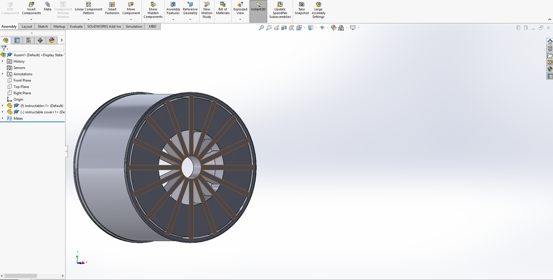
Starting the Cover
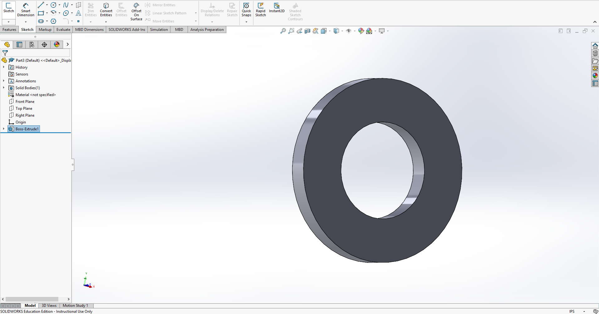
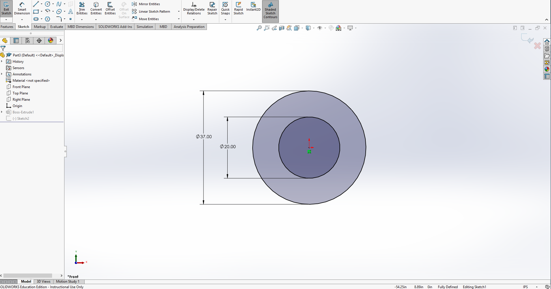
Make two circles, as we will be making a sort of donut shape. The outer circle should be almost as big as the radius of your spokes, leaving a little bit of room to fit it inside the wheel. We will then extrude it the same depth as the spokes, plus about a unit in order to give it strength.
Finishing the Cover
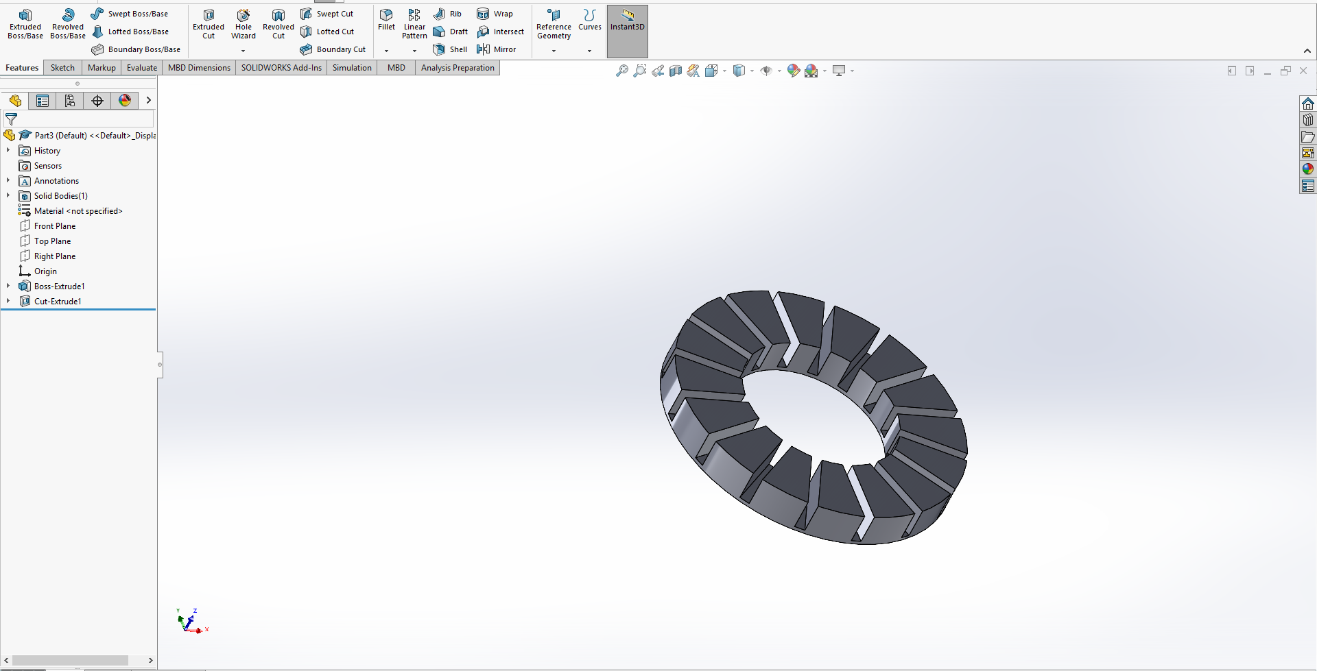
Using the measurements from the spokes of the wheel, we will recreate the design we used. However, this time, we will use the cut feature to give the spokes space to clip in. We will extrude the same amount as the spokes. If done correctly, pushing the cover in behind the spokes will cover the space in between them to reduce drag. This is of course more complicated with a more complicated rim design, but this technique will still work.