Reading Light Values From Witty by Serial Connection
by scanos in Circuits > Microcontrollers
1208 Views, 2 Favorites, 0 Comments
Reading Light Values From Witty by Serial Connection


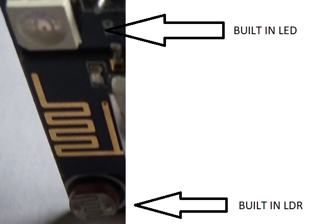
The Witty chip is a wifi board which includes a built in Light Dependent Resistor (LDR) - see attached photo - which enables you to measure light without using external sensors. This instructable shows how simple it is to read these light values and send them to A PC via a serial connection. I assume that you have some Arduino IDE experience.
You will need
- A Windows Device which runs Arduino IDE
- A Witty Cloud ESP8266 (https://www.aliexpress.com/item/32596702416.html?s...
- CP2104 USB 2.0 to TTL UART 6PIN Module Serial Converter
- 2 Dupont Cables
- Micro USB cable with data cables
Programming and set up
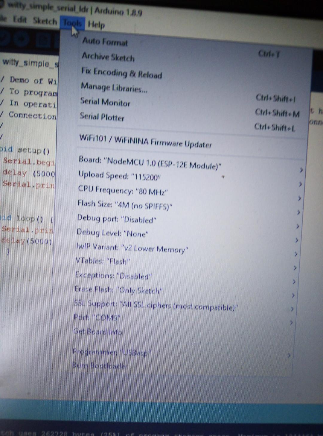
- Set up the Arduino IDE environment as shown in the above image. Ensure that you have the correct boards - (Check File / preferences and ensure that the following is added under Additional Boards Manager url - http://arduino.esp8266.com/stable/package_esp8266c...
- Load the attached Arduino INO file
- Connect the upper and lower sections of the Witty , and connect a micro usb with data pins between the lower Witty section and a Windows PC. Select Sketch / Upload and flash the code onto the Witty.
Downloads
Supplies
https://www.ebay.co.uk/i/173944044686?chn=ps&norover=1&mkevt=1&mkrid=710-134428-41853-0&mkcid=2&itemid=173944044686&targetid=521197490128&device=c&mktype=pla&googleloc=20341&poi=&campaignid=1782815748&mkgroupid=70885937642&rlsatarget=pla-521197490128&abcId=1139356&merchantid=137735224&gclid=CjwKCAjw1rnqBRAAEiwAr29II6gpVWBSjgqYMqw8PSbm-AqNidxra-yvXOgJYszy9vyQJ25rSPLfHxoCoIIQAvD_BwE
Operational Mode and Summary


Running the code
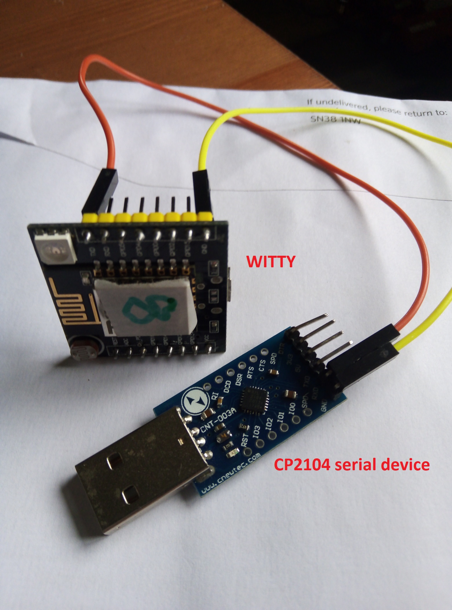
Remove the lower section of the Witty and connect the USB to a 3.3V power source. Don't switch on yet. Next, connect the CP2104 serial device to the usb port of the PC. Then connect as follows:
Connections between serial programmer and Witty as shown in the image above:
Witty TX pin <------> Serial programmer RX pin
Witty GND pin <------> Serial programmer GND pin
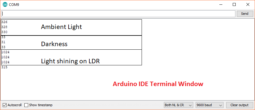
Next, open the Arduino IDE serial monitor and then switch on the 3.3v power source. You will see readings between 0 and 1024 which are proportionate to the light levels detected. See the attached image for typical readings.
Summary
This is a good and very cheap way of learning how to debug Witty programs using the built in TX pins. Of course, you can also connect the Witty RX pin and receive data via a serial connection.
Issues
The Witty appears only to have a single built in analogue port which is quite restrictive. I was able to connect another analogue device to the Witty but even with the LDR covered, there still appeared to be some interference. Another issue is that the Witty only has a single ground and VCC pin which makes life difficult when you want to use the serial debugger and an external analogue device.