Simple Pico Clock
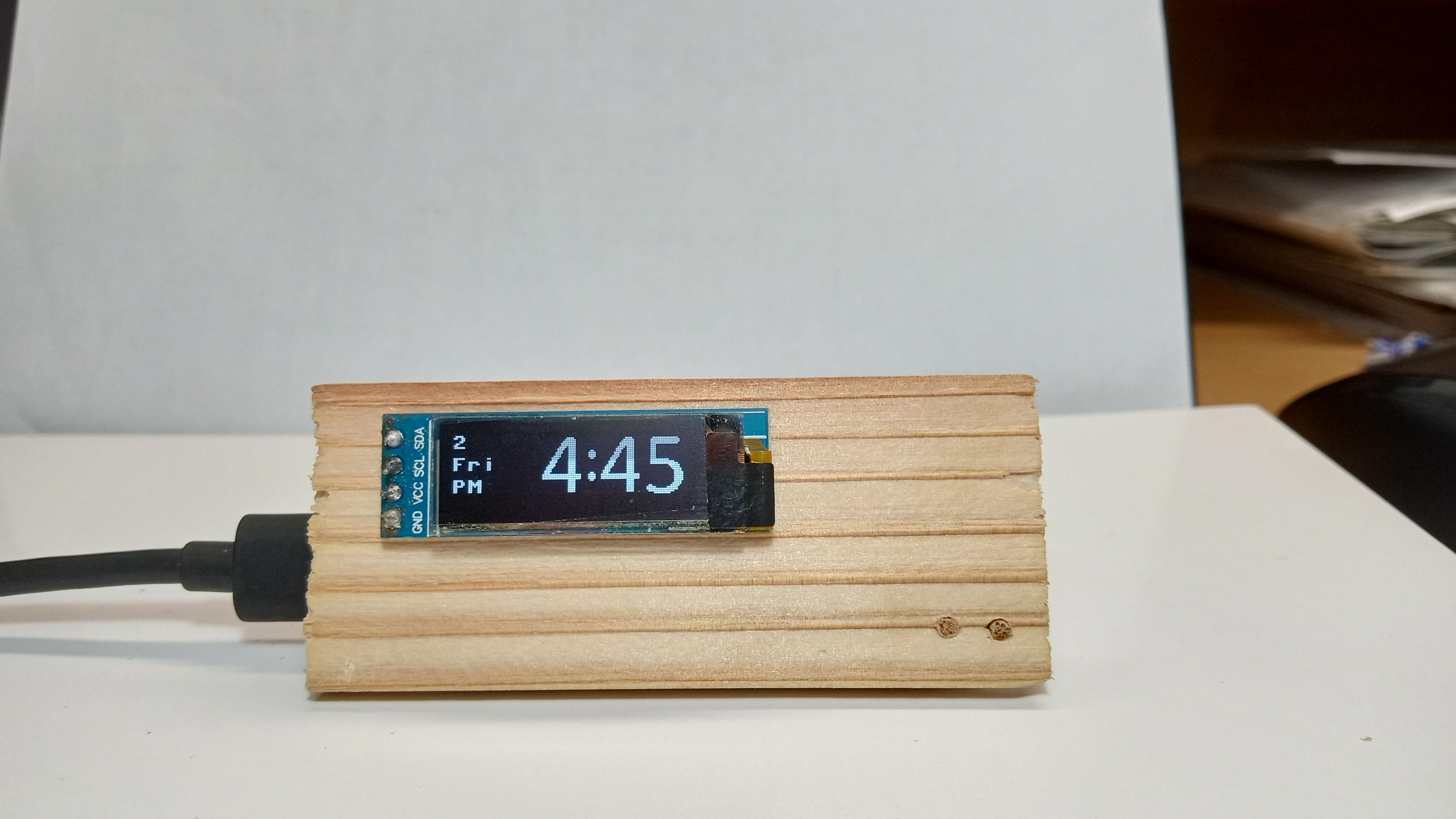
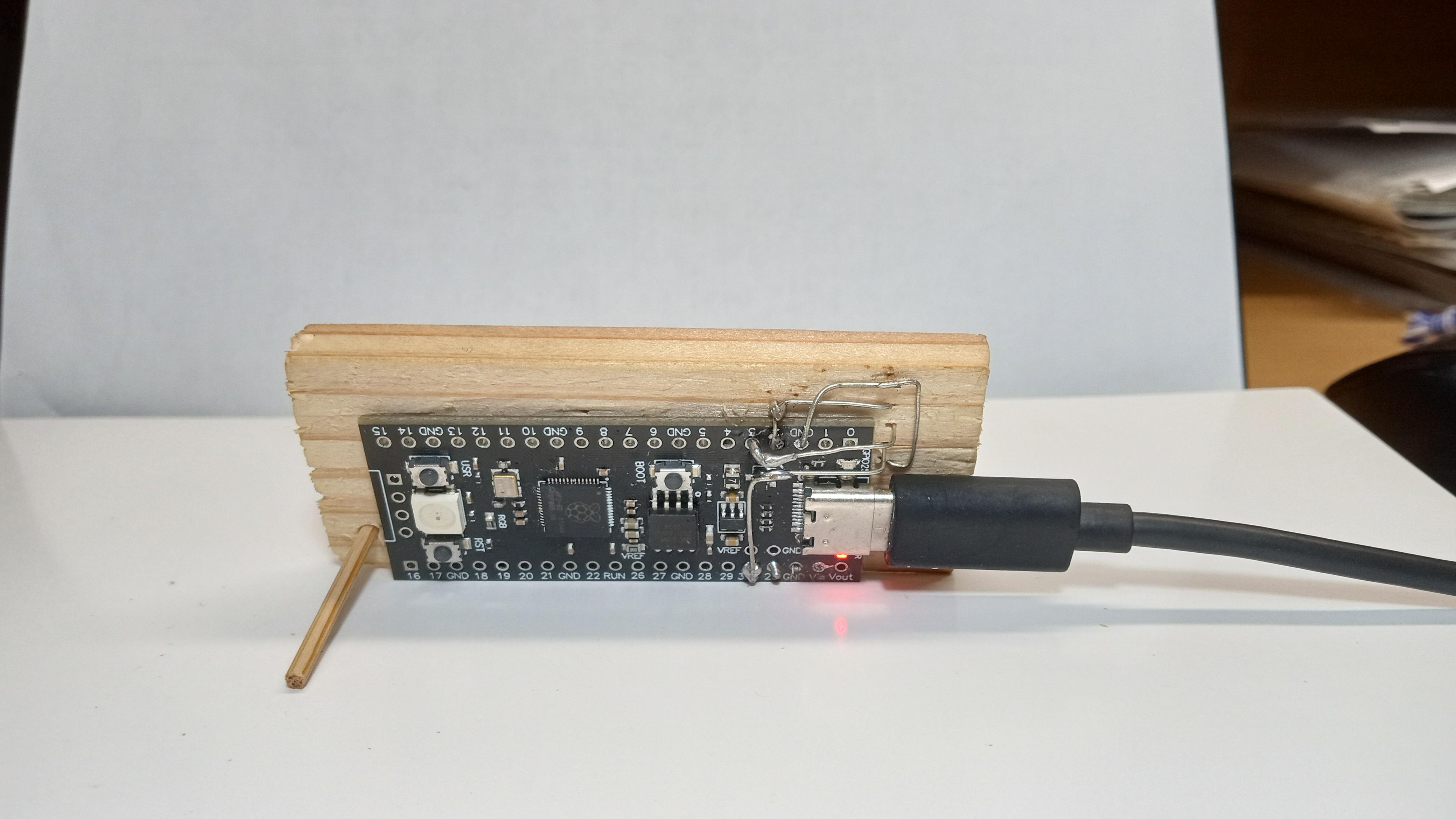
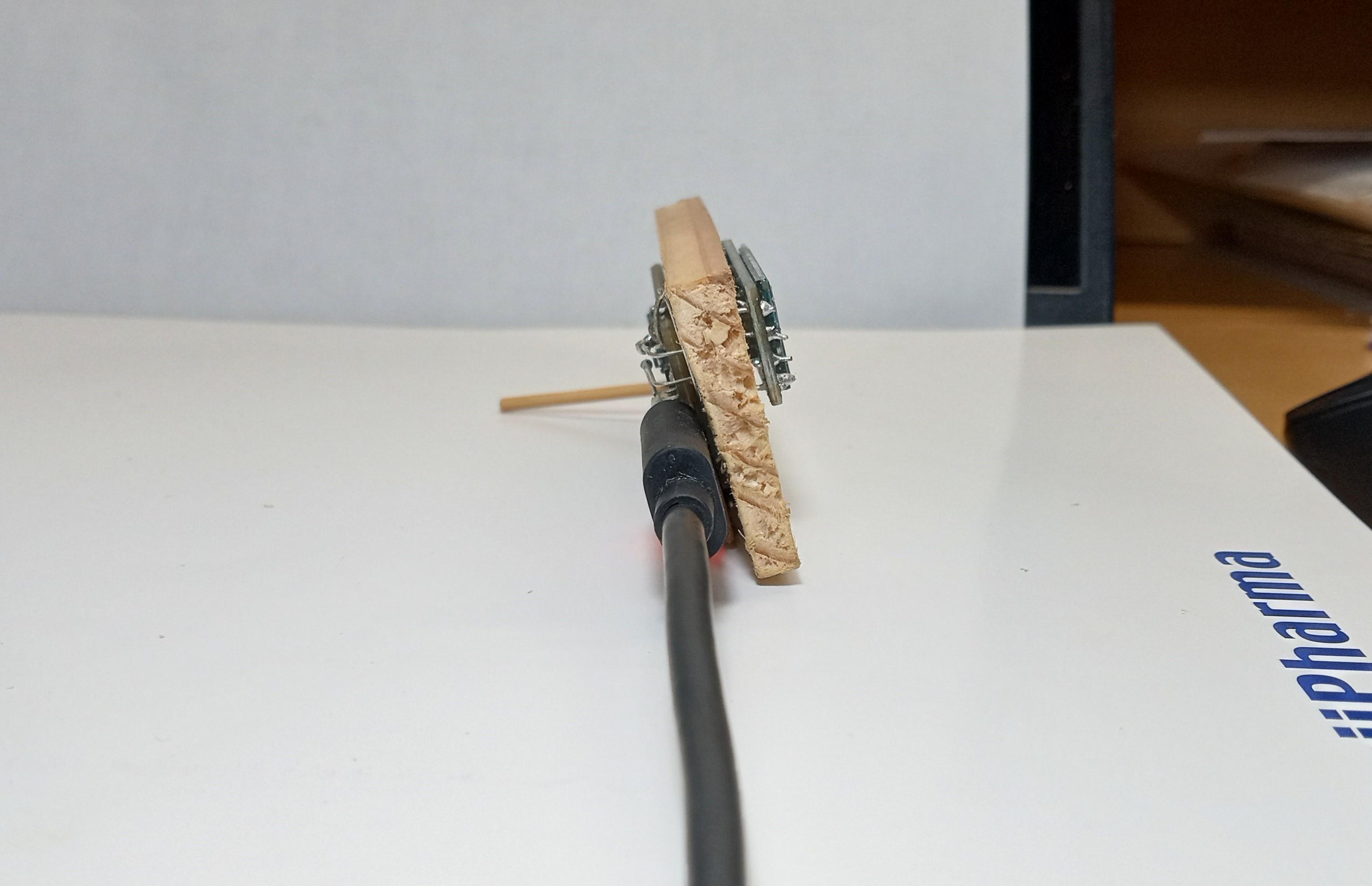
This instructable shows how to make a Raspberry Pi Pico-powered 128x32 OLED digital clock with custom digits coded in MicroPython. It is inspired by jandb86's OLED Digital Clock With Arduino Pro-mini, ElectroPoint4u's PicoClock, and Gokux's Tiny Internet Clock but differs from these project by the following points:
- Much simpler - only requires a 128x32 OLED display, a Raspberry Pi Pico, and a base plate
- Coded with Mycropython - has many of the luxuries of Python, including user-friendly Python syntax, interactive shell, and debugging
- Uses custom digits and icons - look nicer than simple standard fonts
- Powered via Pico's USB port
- Time initialization by coding (or using an optional push button)
The simplicity of the clock makes it a good project for those who have just started learning about microcontrollers (myself included). It's also good if you have a Pico and an OLED display module lying around and are looking for a practical use.
Notes before you begin:
- This project programs a Raspberry Pi Pico using Thony. If you are unfamiliar with how to do this, I recommend referring to the Raspberry Pi Foundation's official page for getting started with Pico.
Supplies
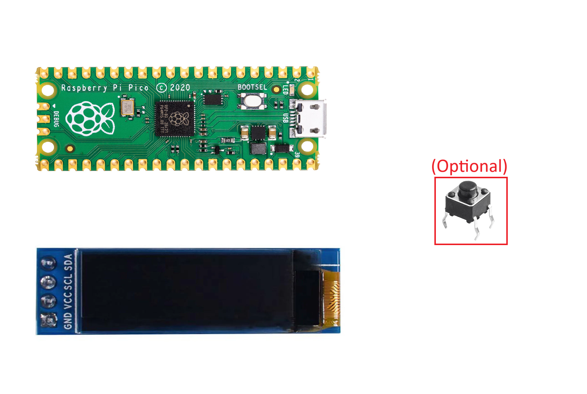
Materials
- A Raspberry Pi Pico - I used a $3 alternative RP2040 board with a user-configurable push button from AliExpress
- A 128x32 OLED display module with an I²C interface
- A base plate for attaching the display and Pico, slightly larger than the size of your Pico (about 3 cm x 8 cm or 1.2" x 3") - I used wood, but a plastic sheet would work too. Alternatively, you can 3D print the base plate using base_plate2.stl provided in Step 1.
- A short ( about 2.5 cm or 1") pin for a stand
- A USB power supply or a mobile battery for powering the clock in the long term
- Double-sided foam tape - for attaching the Pico and display to the base plate
- Some bare or insulated wire
- (Optional) a push button for time configuration - if you want a physical button for setting time, and your Pico does not have a user-configurable button (the official Pico doesn't)
Tools
- A soldering iron, solder, and solder cleaner
- A pin vice/hand drill with a bit of 1 mm (3/32") diameter, or a needle - for making four small holes in the base plate to pass wire from the Pico to the display
- A computer and a USB cable for coding
Make a Base Plate
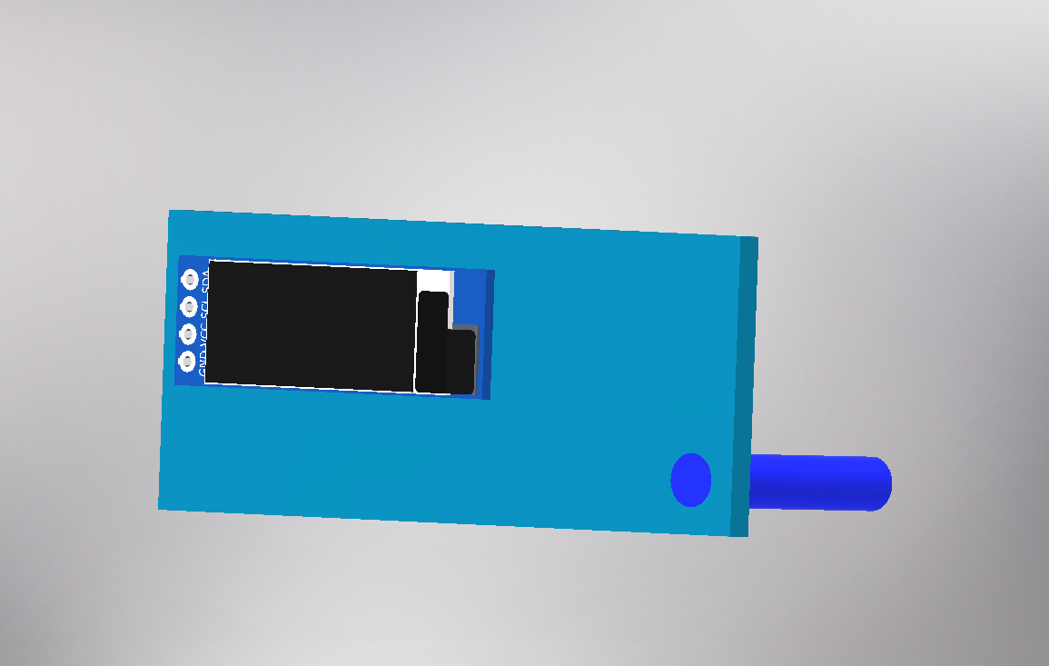
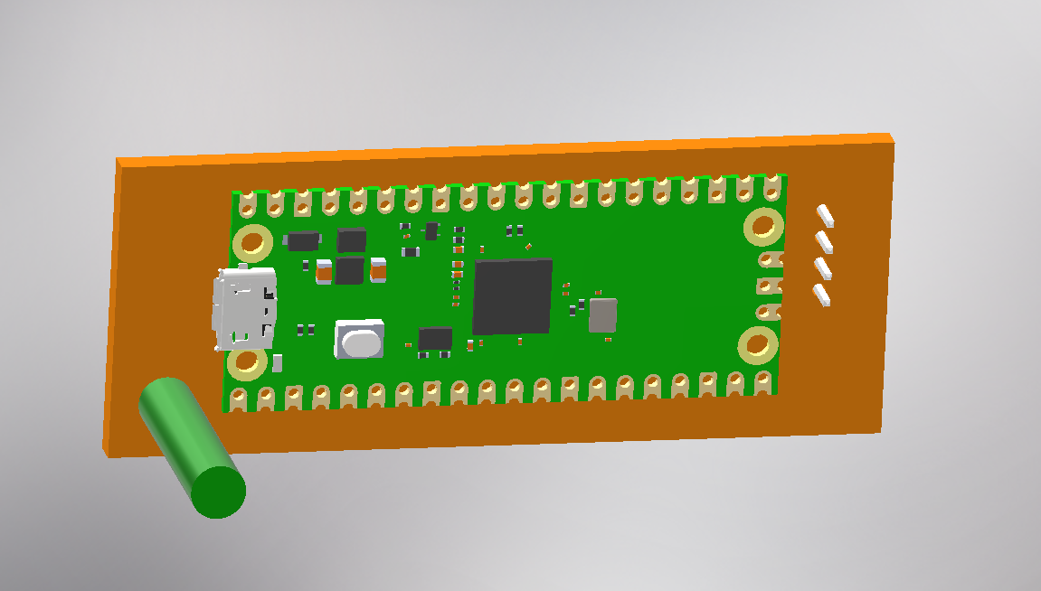
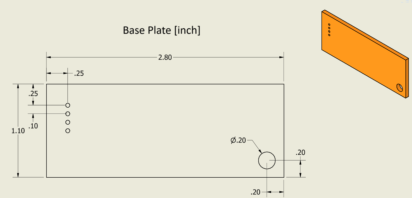
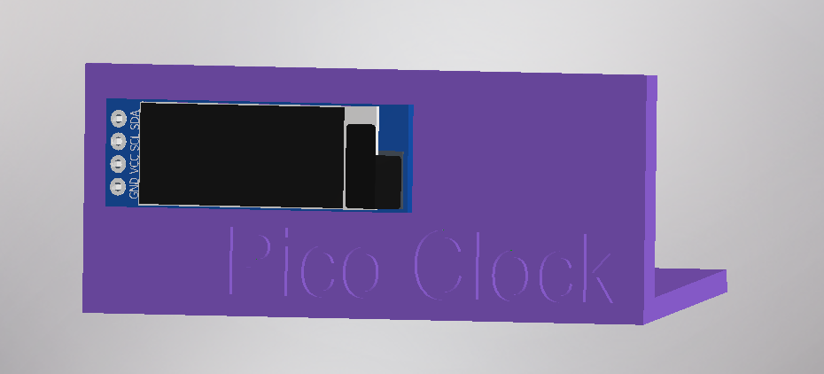
Cut out a base plate to about 3 cm x 8 cm (1.2" x 3"). Decide where to place an OLED module and drill four small holes spaced 0.1" (2.54 mm) apart directly beneath the hole patterns (SDA, SCL, VCC, and GND) on the OLED module. These holes allow wiring to pass through from the Pico on the back of the base plate to the OLED module on the front. Additionally, drill a hole at a corner and push a short (~ 1", 2.5 cm) pin to make a stand so that the base plate stands on its own. Alternatively, you can 3D print the base plate using the stl model base_plate2.stl provided below (place the front face down on the print bed when printing). clock_assembly2.stl below shows the assembled Simple Pico Clock with the OLED module and Pico attached.
Solder I²C Wires
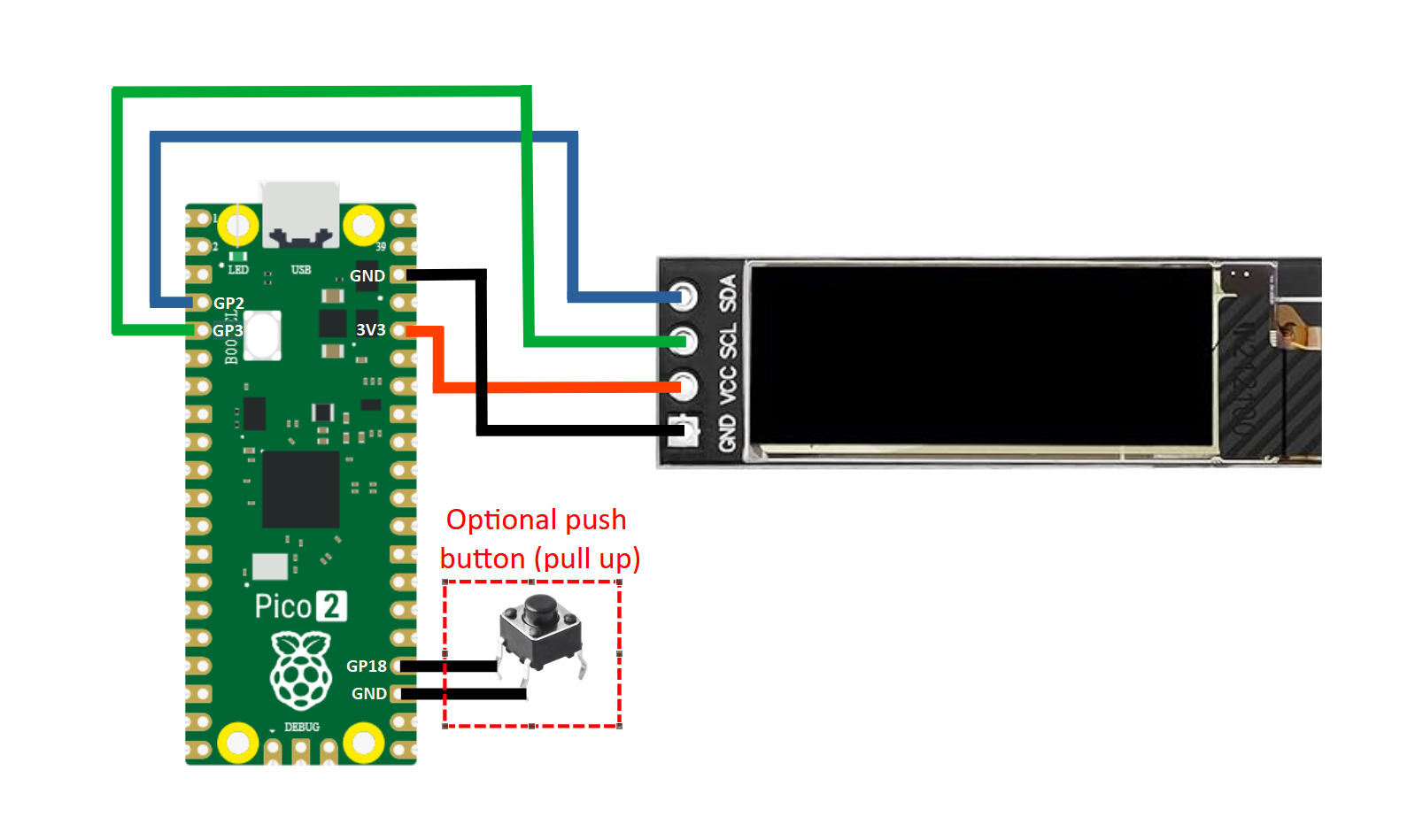
Using double-sided tape (preferably double-sided foam tape), attach the OLED module and Pico to the base plate. Make sure that you can still plug a USB cable to the Pico. Solder four wires from the OLED module to the Pico as shown in the diagram above. Note that your Pico (if it is an alternative RP2040 board) may have a different pinout, but as long as you connect the display's VCC to 3.3V (3V3), GND to GND, SCL to any I²C SCL pin, and SDA to any I²C SDA pin, it should work (don't forget to specify SCL and SDA pin numbers in the code in Step 3). As an option, you can add a pulled-up or pulled-down button for setting time. Some alternative (non-official) RP2040 boards have on-board buttons connected to GPIOs that you can use for this purpose.
Program the Pico
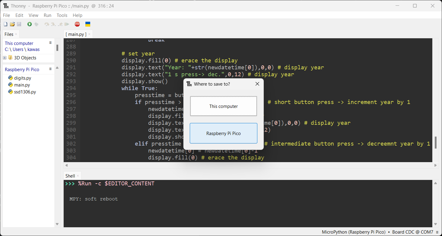
Connect the Pico to a computer using a USB cable and open Thonny. After starting a connection and installing a Mycropython firmware, copy the three scripts main.py, digits.py, and ssd1306.py provided below to the Pico by opening it in Thonny and clicking File > Save as > Raspberry Pi Pico (as shown in the image above). The codes are also hosted at my GitHub repo. The digits.py contains hexadecimal arrays that represent numeric fonts, which main.py takes and displays. The script ssd1306.py (taken from stlehmann's micropython-ssd1306 fork) is a library for ssd1306-based OLED modules that does the actual work of rendering digits on the display.
Before running the script, open main.py and edit entries in the "Parameters" section at the top. Particularly, make sure that the GPIO pin numbers of SCLpin, SDApin, and buttonpin (if you connected a push button) are correct. (If you connected the OLED module and button as shown in the circuit diagram, then you shouldn't need to change these, but it's a good practice to double-check.) You can set the button to be pull up or pull down by changing the buttontype variable. If you did not connect a button, then you need to set the time by editing the settime variable with the current time. I recommend setting this a few minutes ahead so that you have time to save the script and connect the Pico to whatever power source you will be using long-term. The script also has the capability to auto-correct summer/daylight saving time and to show a little cake icon on your birthday. For more details on the script, refer to my GitHub repo.
Setting Time Using a Button
If you connected a push button, you can use it to set the time. To do this, first enable the button by setting timesetbutton = True in main.py line 13. Then set the GP# for the button in buttonpin (line 18), and set buttontype = True if the button is pulled up, or buttontype = False if pulled down. Pull-up means the GPIO pin connected to the button normally receives high (3.3 V), and pull down means the GPIO pin is normally grounded. In the circuit diagram in Step 2, the button is connected between GP18 and GND, hence the GP18 pin needs to be pulled up to normally receive high (3.3 V) so that when the button closes, it receives 0V from GND. If you get confused, imagine there is a physical resistor between 3V3 and GP18 that "pulls-up" GP18 to 3.3 V (in fact, setting buttontype = False sets machine.Pin.PULL_UP when initializing the pin, which does the same thing as placing a pull-up resistor.)
To set time, first press and hold the button for more than 1 sec. This will bring the description screen "<1s press-> inc., >2s press-> next, Press to start'', meaning pressing the button for less than 1 sec increments the entry by 1, and pressing and holding the button for more than 1 sec proceeds to the next entry. From this screen, pressing the button shortly proceeds to the date setting Date: 2. Pressing the button shortly increments date to Date: 3. Pressing the button shortly at Date: 31 brings date back to Date: 1. When date is set, pressing and holding the button for more than 2 sec proceeds to month setting, followed by year, weekday, hour and minute. Note that the date and year can be decremented by pressing and holding the button for more than 1 sec and less than 2 sec. The same button event increases minutes by 10.
(Optional) Make Custom Digits
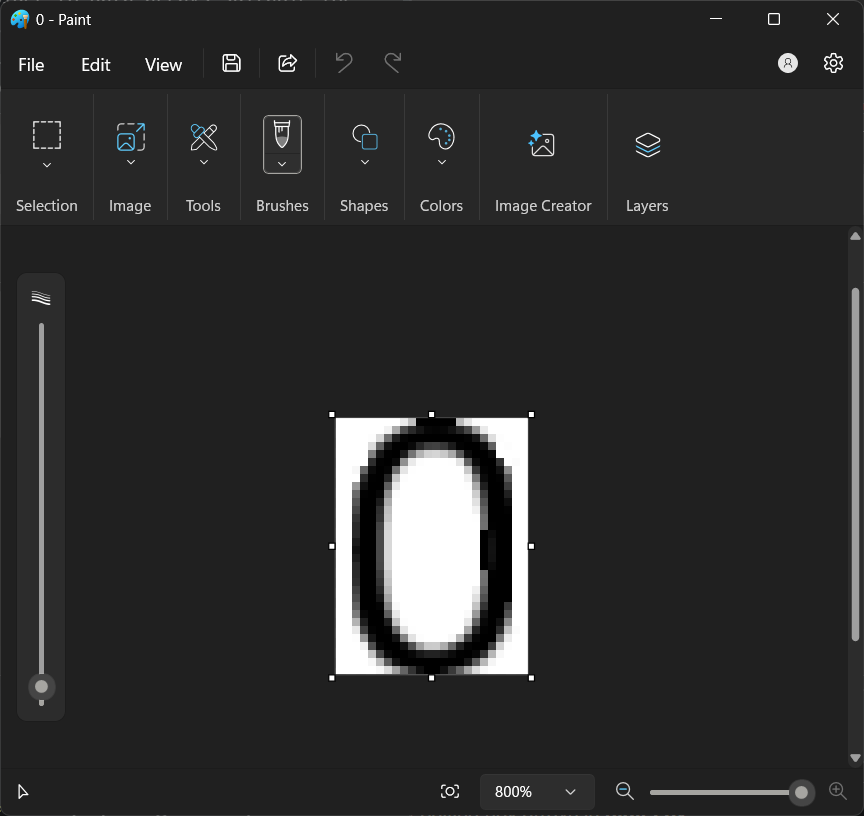
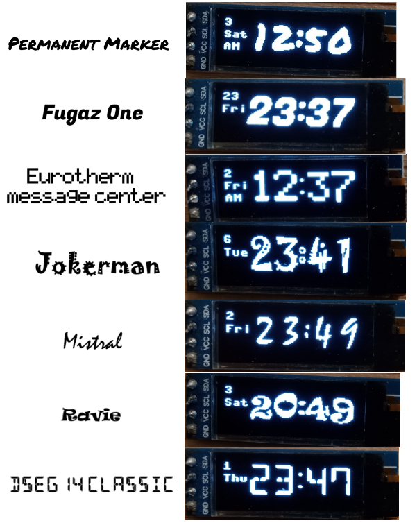
As an option, you can customize the digits displayed on the OLED module by editing the hex arrays in digits.py. Scripts and descriptions for this are available in my GitHub repo. Also, some digits.py files for different fonts I made are available here.