Simple Line Follower Using Arduino
by jithinsanal1610 in Circuits > Arduino
1868 Views, 0 Favorites, 0 Comments
Simple Line Follower Using Arduino

Arduino Line Follower Robot
In this tutorial, we will discuss the working of an Arduino line following robot which will follow a black line in white background and take the correct turn whenever it reaches curves in its path.
Arduino Line Follower Components
- Arduino
- IR Sensor (Array Sensor or 2 Individual Sensors)
- DC Motor
- LIPO Battery
- Robot Chasis
- Arduino IDE
Arduino
You all might be familiar with Arduino; which is the most widely used and fastly evolving electronic platform with so many microcontroller boards and software. For our line following robot, I will be using Arduino UNO which is the most commonly used board.
The Arduino Nano is the best option to get started with electronics and coding if this is your first experience with Arduino Platform. You can use any Arduino Board for this project.
IR Sensor
As mentioned earlier, our line following robot will be following a black line in a white background. So we need something that will ‘see’ the line and tell the line follower to follow the line or to turn around if it is going away from the line. For this purpose, we will be using an IR (Infra Red) Sensor.
Getting Started With PCB
.png)
.png)
Getting the PCB from JLCPCB
EasyEDA is an easier but powerful online PCB design tool which allows electronics engineers, hackers, educators, hobbyists, makers, and enthusiasts to design and share their projects’ schematics as well as PCB layout. This is a design tool integrated LCSC components catalog and JLCPCB PCB service that helps users to save time to make their ideas into real products.
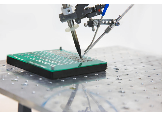
Simply speaking, PCB layout is kind of like a map. A map that connects all components to each other using conducting tracks. It is this design we imprint on a copper cladded board which is then developed to a PCB. Surface Mount Technology is the technique of assembling PCBs by mounting the components on the surface of the board. Unlike the traditional method of placing the components through holes and soldering them on the other side, in SMT, the components are placed over the board and the leads are soldered on the same side.
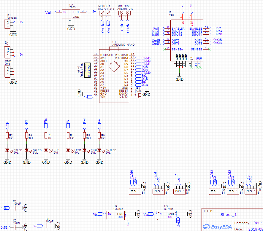
The Circuit
.png)
.png)
To get Started, First Go to EasyEDA website and create a free account. Go to “Editor” and create a new project. For now, JLCPCB have 689 Basic components and 30k+ Extended components at your disposal. See the complete list of components here. Make sure you add the components from this list while drawing the schematics in EasyEDA. You can even search for the components and check its availability.
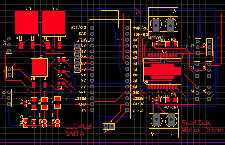
Now you can get your layout done using inbuilt tools in EasyEDA. You can now download the Gerber file and use it to manufacture your PCB from JLCPCB.
Gerber File contains information about your PCB such as PCB layout information, Layer information, spacing information, tracks to name a few. BOM File or Bill Of Material contains the list of all components in the Layout. CPL file(Component Placement List / Pick & Place File (PNP) file), it is used by automated SMT Assembly machines to determine where each part should be located on the board.
Ordering the PCB
.png)
.png)
.png)
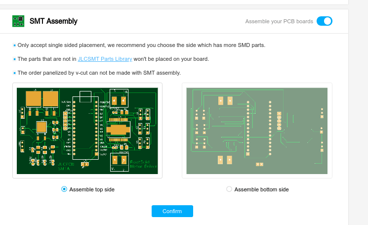
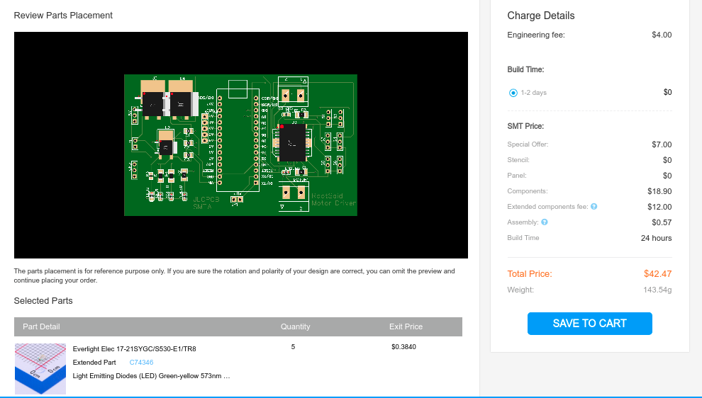
Go to JLCPCBs website and Click on “Quote Now” and upload your Gerber File. Once the Gerber file is uploaded, it will show you a preview of your circuit board. Make sure this is the PCB Layout of the board you want. Below the PCB preview, you will see so many options such as PCB Quantity, Texture, Thickness, Color etc. Choose all that are necessary for you.
Click on “Assemble your PCB boards”.
Now, you will have to upload the BOM and CPL file that we downloaded earlier. Select all the components you want JLCPCB to assemble in your PCB. Simply click on the confirm box to select the components.
In this page, you can review your order. You can check the layout, see all the components and if there is any problem, you can click on “Go Back” to edit your order.
Once everything is done, click on “Save To Cart”. In the next page, you can choose a shipping and payment option and Check Out Securely. You can either use Paypal or Credit/Debit Card to pay.
The PCB will be manufactured and shipped within days and will be delivered to your doorstep within the mentioned time period.
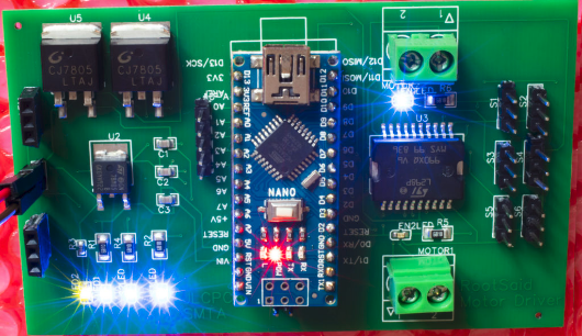
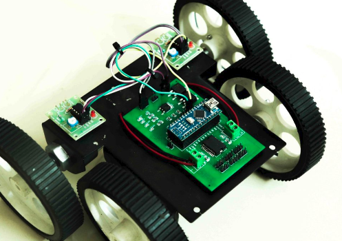
Assembling the Robot
Now let us start building the Robot of our Arduino Line Follower. Here we are going to build a 4 wheeled robot, with 2 DC Motors connected on either side (front) and two dummy wheels on the back side. As mentioed earlier, we will be using Arduino UNO board to get input from the sensors, process them and send signals to L293D motor driver IC to drive the DC motor motor of Line Following Robot Arduino.
L293D
Below you can pin out diagram of the L293D IC. As you can see it has two pins for inputting voltage. One of them is for powering the internal circuit of the IC and the other for driving the motor.
Pin 8 – Driving the Motors – 4.5 V to 33 V Pin 16 – Working of the IC– 5V If you happen to reverse this connection accidentally, you may burn off the chip. This IC have two H Bridge circuits and so it is capable of controlling two motors individually at the same time. One side of this IC controls one motor and the other side controls the second motor. For the motor to work, the Enable pin of that side should be High.
The enable pins can also be used to control the speed of the motor using PWM (Pulse Width Modulation). If you want to know more about L293D and working of H-Bridge, follow the link below. Click Here to Learn the working of an H Bridge Motor Driver So we have two wheels.
How does this line follower goes forward, backward, left or right?
The logic is pretty simple. When both motors rotate the same direction (clock wise or anti clock wise), the arduino line follower will move forward or backward. If both moves in opposite direction, the line following robot will turn left or right.
You will get complete connection diagram here - > Line Follower Complete Tutorial
Uploading Code and First Run
The code is really easy to understand and if you have any queries regarding the codes, feel free ask it in the comments or in our community. You will get complete code from here.
Upload the code, power up, and place your Arduino Line Follower Robot in black line and see the robot in action.
Had fun? In the next chapter, I will show you how to include PID Algorithm in our Arduino Line Follower to make our robot more smooth and fast by controlling the speed of the motor. Subscribe RootSaid for more awesome projects.