Simple LED Thermometer

This page is meant as a final design review for an introductory circuits class. While this Instructable does not follow the typical format, we hope that you may find this as an interesting application of op amp comparators and thermistors in a practical application.
Preliminary Design Review
This project is designing a sensor that will measure the ambient temperature in a room and use a series of LEDs to communicate the recorded temperature. To do this we will be using a NXFT15WF104FA2B100 thermistor. This thermistor will be designed to read temperatures between 60°F and 85°F so, we will be able to calibrate the thermistor in this range by determining exactly what resistance it has at these temperatures. Since our sensor is a variable resistor, there is no input or excitation voltage required, instead, we will use a resistive divider to read the change in voltage. We will measure the voltage over the thermistor which will allow us to observe a change in voltage as the resistance of the thermistor changes. Although the resistive divider will allow us to get the voltage into the range we need, the signal will likely be noisy. So, we will use an MCP601 Op-amp as a unity gain buffer to filter the signal.
Since the purpose of our sensor is to communicate the ambient temperature, we will be using a series of LEDs to show what temperature it is. We will have 4 LEDs and the more LEDs that are on, the hotter the temperature. When the temperature is below 65°F no LEDs will be on, when it is between 65-70°F, 1 LED will be on, when it is between 70-75°F 2 LEDs will be on, when it is between 75-80°F 3 LEDs will be on, and finally if the temperature is hotter than 80°F, 4 LEDs will be on. To achieve this we will use the resistive divider to get the conditioned output voltage to be less than 1V at 65°F and roughly 5V at 80°F. To determine the resistance of the thermistor at various temperatures, we created a plot of the resistance of the thermistor vs temperature (°C). The plot is shown below
The sensor will work by employing a set of diodes in parallel. As the temperature increases resistance of the thermistor will decrease and the voltage at Vout will increase. Since our parallel LEDs are connected between Vout and ground, as the temperature increases the voltage between the 2 rails of our parallel circuit will increase. In series with each LED will be a resistor to limit the current as well as a diode to increase the forward operating voltage of each leg of the parallel circuit. Since each leg of the parallel circuit will have different forward operating voltages, the LEDs in each leg will turn on at different temperatures. A block diagram of the system is below.
To build the sensor we will need: 1 thermistor, 1 op amp, 5 resistors, 4 LEDs and 4 diodes. First, we will make a resistive divider with the thermistor and a resistor such that when powered by 9V we will have a usable voltage range of 1V to 5V. This will allow us to have an output voltage as the resistance of the thermistor changes. The voltage over the thermistor will be our output voltage. Then we will filter the output voltage of the resistive divider using the MCP601. The output of this op amp will be a lot cleaner for use in our LED circuit. To make a different number of LEDs turn on at various voltages, we will use 4 LEDs in parallel. In each branch there will also be a current limiting resistor to prevent LED burnout and an additional diode that will change the forward operating voltage for each branch. Each branch will have a different forward operating voltage so that as the output voltage increases and surpasses each of the branch forward operating voltages, the associated LEDs will turn on.
The timeline for this project is as follows:
Week of 11/13-11/18
Determine the resistor and Diode values
Weekend of 11/18-11/20
Calibrate thermistor
Build first prototype of circuit
Thanksgiving Break
Weeks of 11/28-12/06
Troubleshoot, iterate, write up final report
The sensor we are making will be a fairly safe circuit. Electricity always has the potential to be dangerous, but to avoid danger and risk, we are working with low voltage (9V). The biggest safety hazard that we forsee is that too much current goes into the diodes and causes them to get dangerously hot or burnout. To avoid this, we will use resistors in each branch to reduce the current and mitigate the risk of the diodes burning.
Critical Design Review
After reviewing our previous design with Tau Beta Pi tutors, we decided to pivot from our initial plan of using 4 parallel LEDs each in series with additional diodes. We found that this required us to rely too heavily on our voltage divider with the thermistor, required lots of diodes in series, and after performing some tests we found that the LED turned on very gradually, rather than all at once as we desired. So, we decided to switch our design to using 4 op-amps as comparators. The thermistor will be in a voltage divider and Vout will be the voltage over the thermistor. Vout will go into the V- terminal of each comparator and a calibrated reference voltage will go into V+. When V->V+ the output of the op-amp will rail to Vcc-. When V+>V-, the output will rail to Vcc+. We are supplying our op amp with Vcc- = 0V and Vcc+ = 5V. So as the temperature increases, Vout will decrease and the V- terminal of each comparator will decrease. When it goes below the reference voltage, the op-amp will rail out, powering each LED. The reference voltage of each comparator was selected based on the thermistor data so that each op-amp powers the LED when a temperature threshold is crossed. For our comparators, we are using the MCP6004 and for our thermistor, we had to change to thermistor to the NXFT15XH103FA2B025 based on availability.
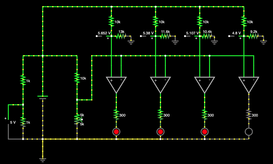
Our full circuit diagram is given by:

When designing our circuit we needed to know what values to pick for each of our resistive dividers so that the voltage divider with the thermistor outputted the ideal voltages and each of the comparators had the proper reference voltages. Using the data sheet of the thermistor, we were able to create a curve that models the resistance of the thermistor as a function of temperature. The equation for that curve is given by:
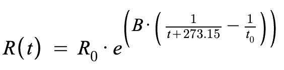
Where R0=10kOhms, for our temperature range, B = 3428K, and t0 = 298.15K. Using this equation we can determine the expected voltage that the voltage divider will output at each of the temperature thresholds. We found that at 65°F Vout = 5.65V, at 70°F Vout = 5.38V, at 75°F Vout = 5.1V, and at 80°F Vout = 4.84V. To create these threshold voltages at each of our comparators while only requiring 1 power supply, we employed 4 resistive dividers. Selecting R1 arbitrarily we were able to determine each value of R2 such that all of the comparators had the proper reference voltage. These values can be seen in the full circuit diagram pictures above. All of the voltage ranges for powering our op-amps as well as the values for V+ and V- are well within the appropriate range for the MCP6002. The op-amps will power each LED with 5V and a max current of 23mA. Our LEDs have a max allowable current of 20mA so to condition the voltage, we added a 300 Ohm current limiting resistor to limit the current to a safe 11.33mA.
Finally, the circuit will be powered with DC voltage and thus we do not need to worry about the frequency response of the circuit. Additionally, our circuit does not require a substantial amount of power, so no modifications need to be made.
To make sure that our input sensor, a thermistor, would behave correctly, we tested the thermistor at various temperatures in the expected temperature range (18.33°C and 26.67°C) to see how it compared to our theoretical model. We measured the resistance of the thermistor as well as the output of the thermistor in the planned 10kOhm voltage divider. The results of the testing are below.

The results of the testing show that the theoretical model of our thermistor gives a very good approximation for our actual thermistor, however, the voltage output of our voltage divider consistently varies by 0.1V, equivalent to about 1°C. Although this difference is very small it is not negligible and needs to be accounted for. Before we prototype the full circuit, we will retest our thermistor at exactly the boundary temperatures and adjust the threshold temperature of each comparator accordingly. It is likely however that the selection of resistor we have to make the comparator reference voltage dividers is not comprehensive enough to capture the difference, but we will try regardless. Despite the small difference in resistance of the thermistor, the testing proved that our modeling and assumptions regarding the thermistor were correct and we do not need to overhaul our circuit design, just change a few resistor values.
On top of testing the input stage of the sensor, we also simulated the entire circuit in the Falstad circuit simulator. We simulated it with the theoretically found voltages since we have not yet performed comprehensive sensor testing. The op-amps in the simulator are powered by Vcc- = 0v and Vcc+ = 5v although it is not displayed on the simulation screen. The voltage divider on the left side of the circuit demonstrates how we will acquire the 5v power source. Additionally, we used a potentiometer to demonstrate the variable resistance thermistor. A screenshot of the simulation at 77°F is shown below. We can see that 3 of the LEDs are on and 1 of them is off as we would expect from this configuration. Additionally, all the currents and voltages are well within safe ranges for all of our components. All of the comparators and reference voltages work so far in the simulation and there are a few scope probes to measure the reference voltages. We expect that when we build the actual circuit we will get slightly different results due to resistor tolerances and loading and thus we may need to tweak a few resistor values in the prototyping and iteration phases.
Final Design Review
After analyzing the data we collected in our testing, we decided that the theoretical thermistor voltage divider output was not close enough to the measured output voltage to use that. Instead, we used the data we collected during week 3 to create a voltage curve for the voltage output of the thermistor voltage divider. The equation for the voltage curve we determined experimentally was:
Vout = 7.7827e-0.019T
Where T is the temperature in Celsius. Using this equation we determined that for our 4 comparator voltage dividers the resistors for the 4 comparators needed to be: 12192.6 Ω, 10881.2 Ω, 9774.57 Ω, and 8828.846 Ω. These resistor values are highly irregular and would be incredibly challenging to recreate using resistors from the lab. So, we decided that instead of a series of resistors each comparator would have a input from a voltage divider that uses a 10kΩ resistor and a 25kΩ potentiometer to get the appropriate voltage. This would also allow us to change the resistance of the potentiometer based on the results of testing to take into account resistor tolerances, parasitic elements, and loading.
The other design change that we made was adjusting the current limiting resistors in each LED circuit. We found during testing that using equivalent resistors for each LED caused 2 of the LEDs to shine much brighter than the other two. To make it so that all LEDs were visible and fairly equally lit, we changed the resistance of the current limiting resistor in each branch. Originally all of the LEDs had a 330Ω resistor. Now 2 branches have a 1kΩ resistor, 1 branch has a 150Ω resistor, and one branch has a 330Ω resistor. These values were determined experimentally and which branch each resistor is in can be seen in the annotated image of the circuit below.
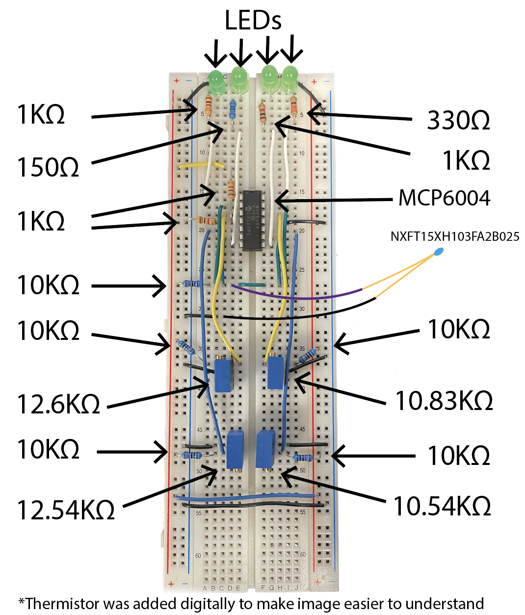
Image of Annotated Circuit Diagram
After completing our circuit, we tested the circuit at the exact temperature barriers we specified to make sure that the circuit performed as expected. Unfortunately, with the resistance values we had determined, the circuit did not quite perform correctly. The LEDs turned on and off a couple of degrees away from the desired temperature ranges. To fix this, we created temperature baths at the temperature we were interested in using as our barrier and adjusted the potentiometers accordingly. After adjusting the potentiometers tNow the circuit works as expected. When the temperature is less than 65° F, no LEDs turn on, when the temperature is between 65° F and 70° F, one LED turns on. Similarly, when the temperature range is from 70°F to 75°F, two LEDs turn on, and when the temperature range is from 75° F to 80°, three LEDs turn on. Finally, when the temperature is above 80° F, all four LEDs turn on. The resistance values of each potentiometer are now 12.6kΩ, 12.54kΩ, 10.54kΩ and 10.83kΩ respectively. All of these values are different from the analytic calculations due to resistive error propagation throughout the circuit, which validates our choice of using potentiometers to adjust resistances experimentally. A video of the circuit behaving correctly can be seen here - https://youtu.be/h4ws8FJxgLg