Simple IoT Power Outlet Using Standalone ESP8266 and Cayenne
by Kuncono in Circuits > Microcontrollers
10161 Views, 49 Favorites, 0 Comments
Simple IoT Power Outlet Using Standalone ESP8266 and Cayenne
Hi, I'm newbie to programming and this is my simple project to create smart switch (power outlet) for the bulb using ESP8266 as standalone with a little modification.
I'm sorry for my bad english. I'm Indonesian. I didn't expect that ESP8266 could work with Cayenne.
I choose ESP as main unit because it's realy cheap, only need one GPIO, and the size is very small that fit to my ex timer case.
WARNING : THIS IS ELECTRICIAN MAY SHOCK YOU. BE CAREFULL !!!
Bill of Materials

- Hardware
- ESP8266 ESP-12F
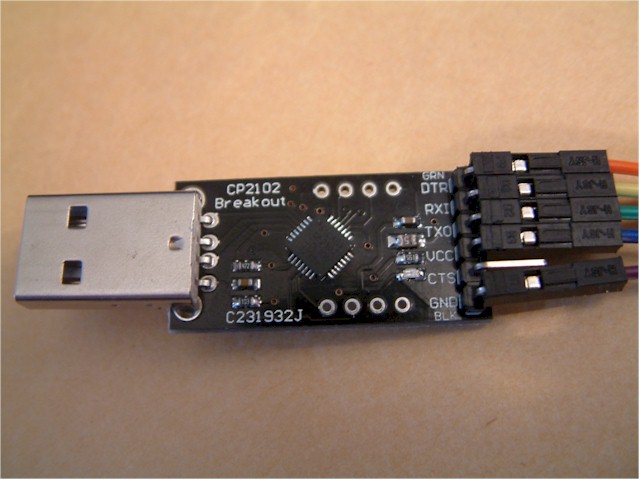
- CP210x USB to UART
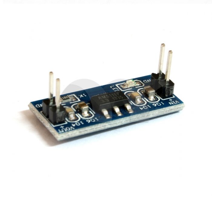
- 5V to 3.3V Step Down Converter
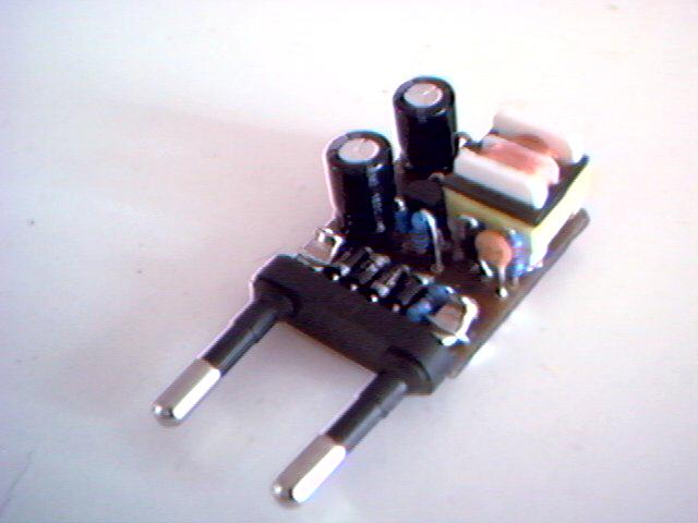
- 5V Generic Power Supply
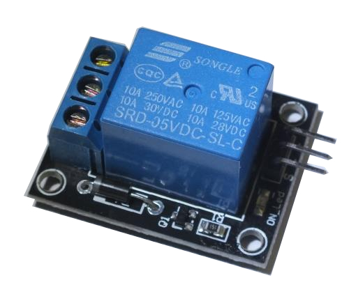
- 1 Ch 5V Relay
- Cables
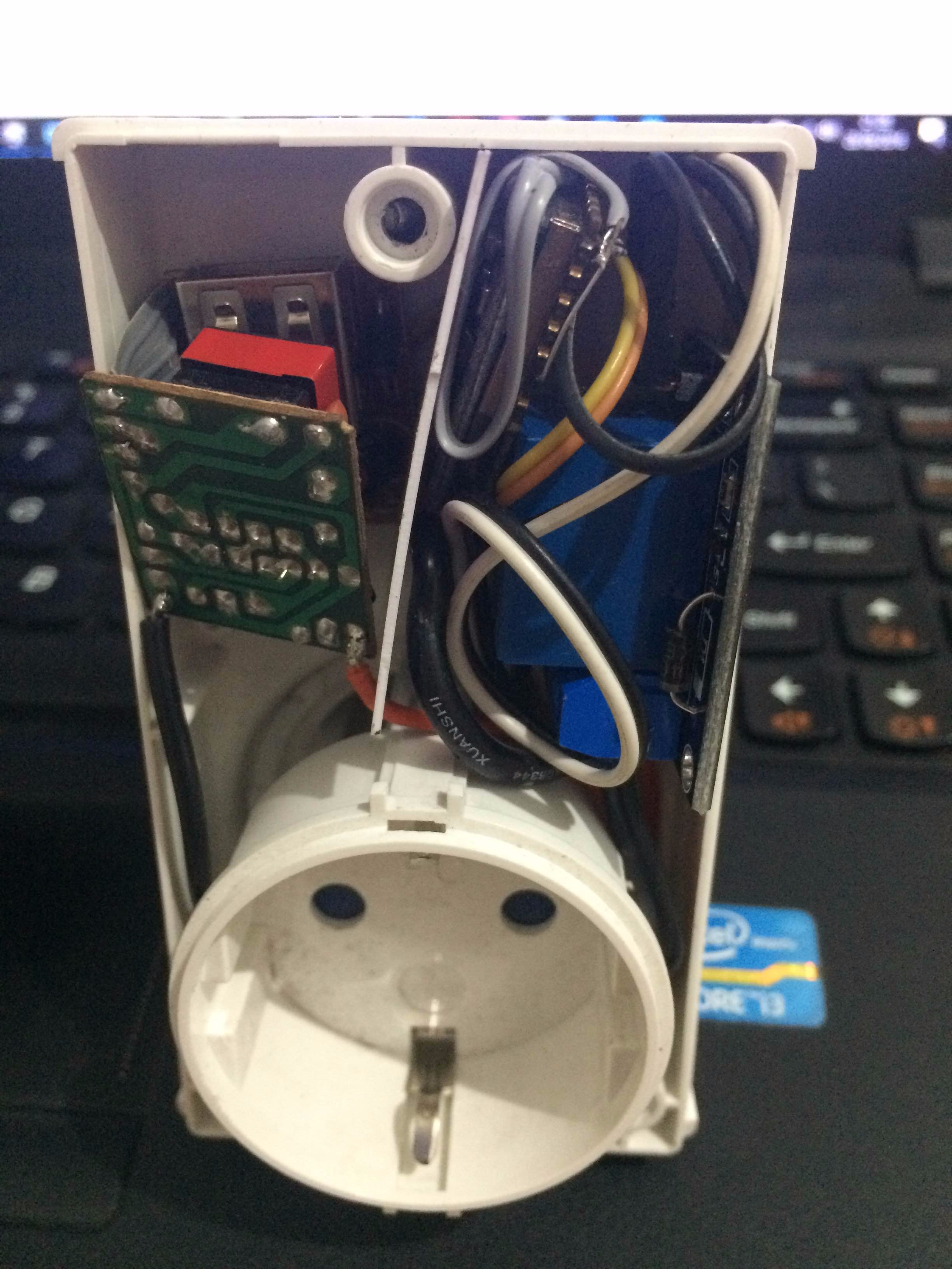
- Case (I use ex timer power outlet)
- Software
- Arduino IDE
- Cayenne Library for Arduino
- Cayenne for iOS or Android or Cayenne Website
- Register to Cayenne and get your token
Connect and Upload Code to ESP Via USB UART
Connection Map :
USB UART ESP
3.3V VCC & EN/CH_PD
GND GND & GPIO0 & GPIO15
TX RX
RX TX
On Arduino IDE :
- Import Cayenne library from here
- Select Generic ESP8266 Module from Tools -> Boards
- Select Port which connected from Tools -> Port
- Upload code to ESP Board
Downloads
Connect ESP to Relay Module and Ready to Use
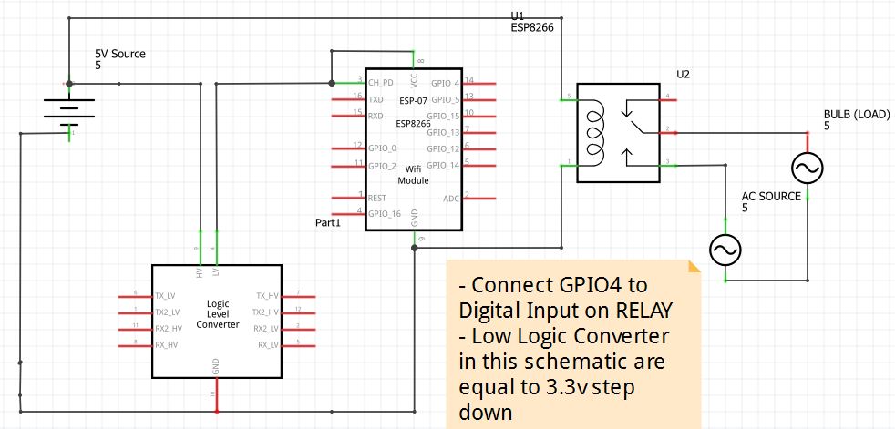
- Release the GPIO0 from GND
- Connect GPIO4 to Relay digital signal
- Connect 5V Power Supply to VIN 3.3V Step Down Converter and VCC&GND Relay VIN
- Connect 3.3V VOUT to VCC and GND
- Connect GPIO15 to GND
- Connect L AC Power Source to middle relay switch and connect NO to the power output
- Connect N AC Power Source directly to power output
- Open Cayenne on your device, add new Arduino device, add new light switch, select virtual pin 1, and save
- Your plug is now connected as IoT
I'm sorry for the bad instruction, I'm very new comer.