Simple Gyroscopic Motion Visualizer
by TechMartian in Circuits > Sensors
3512 Views, 21 Favorites, 0 Comments
Simple Gyroscopic Motion Visualizer
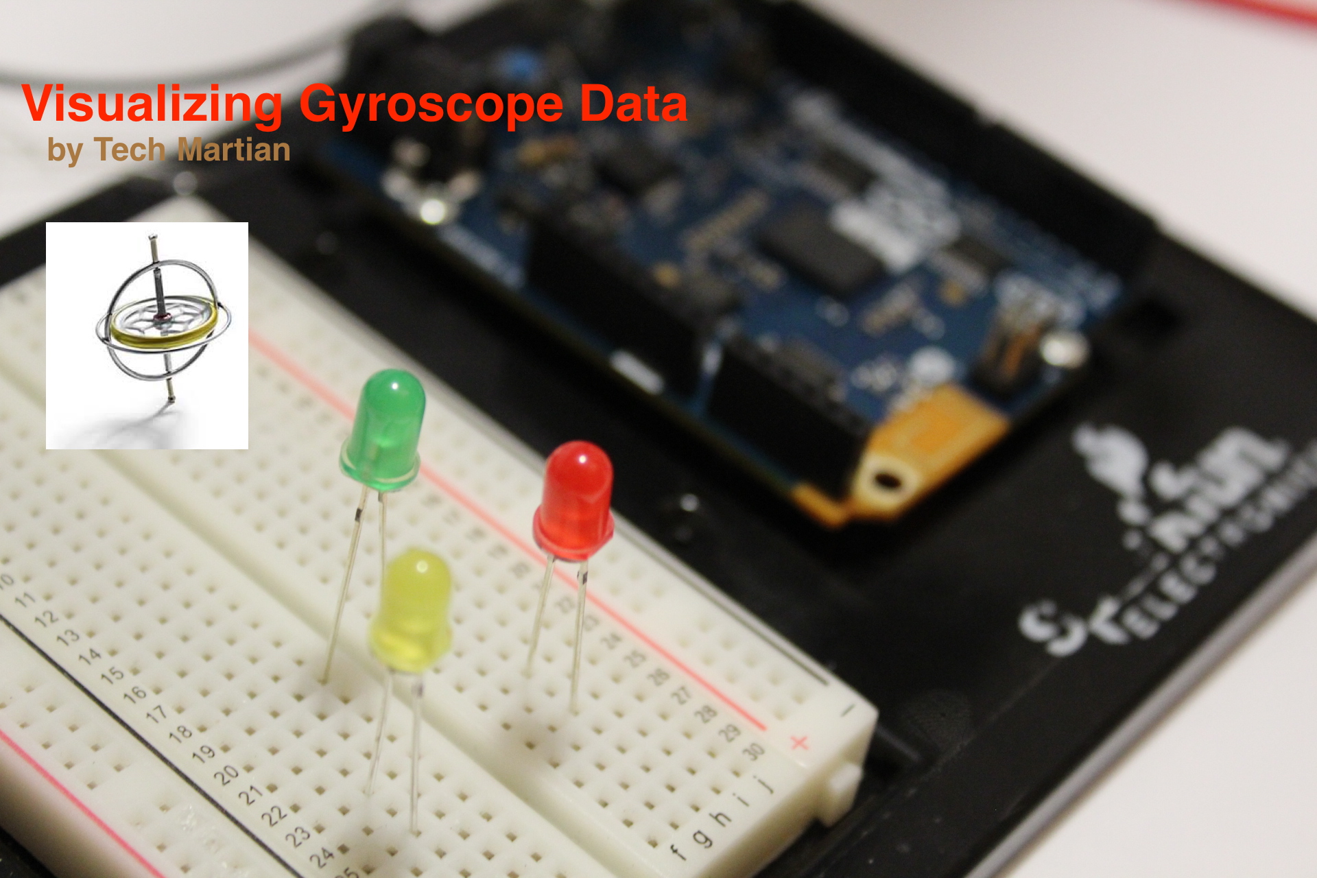
This uses 3 LEDs to represent each of the axes of the gyroscope. While the values of the gyroscopic tilt are represented visually by a change in brightness of the LEDs.
Gyroscope motions is not intuitive to visualize and it is more difficult to have an intuitive grasp of the values outputted by a gryroscope. Nevertheless, the gyroscope is one of the three main important sensors for an Inertial Measuring Unit (IMU).
My goal is to have a solid intuitive understanding of the nature of the gyroscope data from the Arduino such that I may apply it to future projects with ease. With this quick and easy setup, I can easily visualize the motion, as well as debug applications!
BoM
- Arduino 101
- 5mm Green LED
- 5mm Red LED
- 5mm Yellow LED
- 3 pieces of 100Ω resistors
- Jumper Wires
How It Works?
The Arduino 101 has a built-in sensor which the Curie chip on the Arduino 101 can process. Since the chip is manufacturedfy Intel instead of Atmel, we have access to the Intel-built Curie libraries which will make the gyroscope raw value readings much simpler. The gyroscope raw readings are gotten using the CurieIMU library which is then used to find the relative output of the LEDs by mapping.
The LED brightness can be controlled using PWM pins on the Arduino board which simulates analog-like signal from changes in the duty cycle. By using the specially marked digital PWM pins as output, we can control he brightness of each of the three LEDs that are each associated with a cartesian axis with respect to the the gyroscope data.
Seeing the Numbers
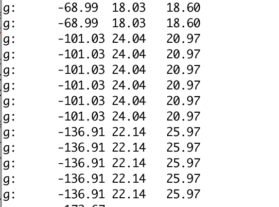
To get an appreciation of visualizing the gyroscope motion, we'll first have a look at raw data. The following code will output raw data of the Gyroscope onto Serial Monitor.
#include <CurieIMU.h>
void setup() {
  Serial.begin(9600); // initialize Serial communication
  while (!Serial);    // wait for the serial port to open
// initialize device
Serial.println("Initializing IMU device...");
CurieIMU.begin(); // Set the accelerometer range to 250 degrees/second CurieIMU.setGyroRange(250); }
void loop() {
  float gx, gy, gz; //scaled Gyro values
// read gyro measurements from device, scaled to the configured range CurieIMU.readGyroScaled(gx, gy, gz);
  // display tab-separated gyro x/y/z values
  Serial.print("g:\t");
  Serial.print(gx);
  Serial.print("\t");
  Serial.print(gy);
  Serial.print("\t");
  Serial.print(gz);
  Serial.println();
}
Downloads
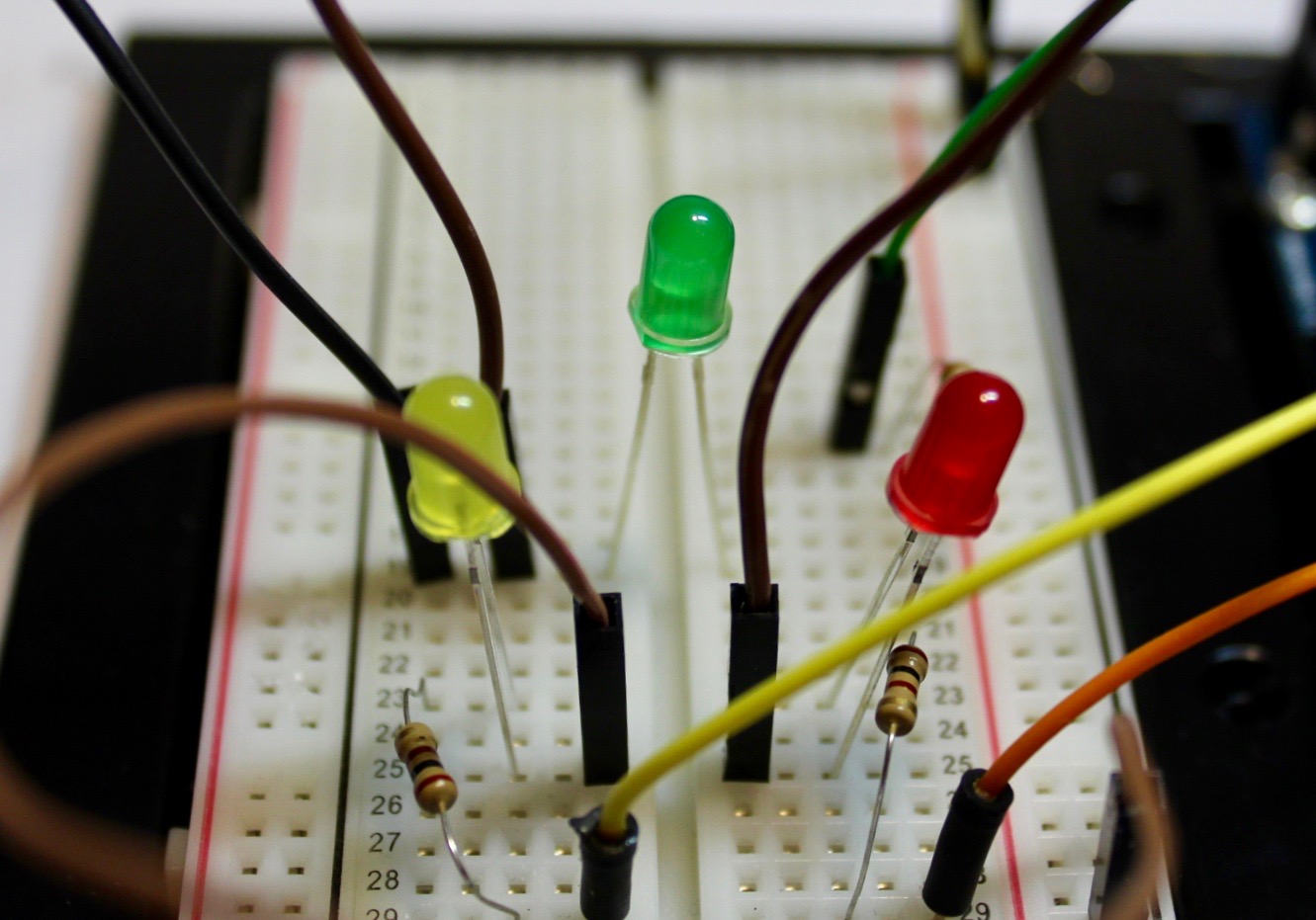
Connecting the LEDs
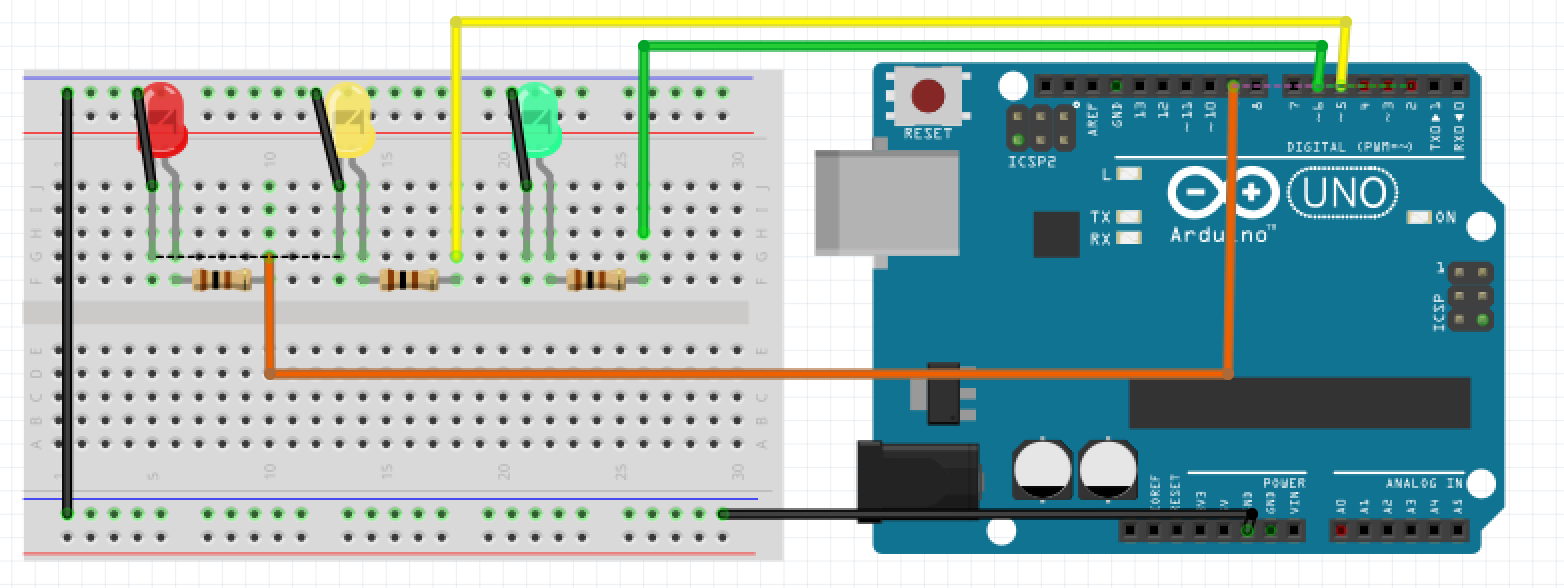
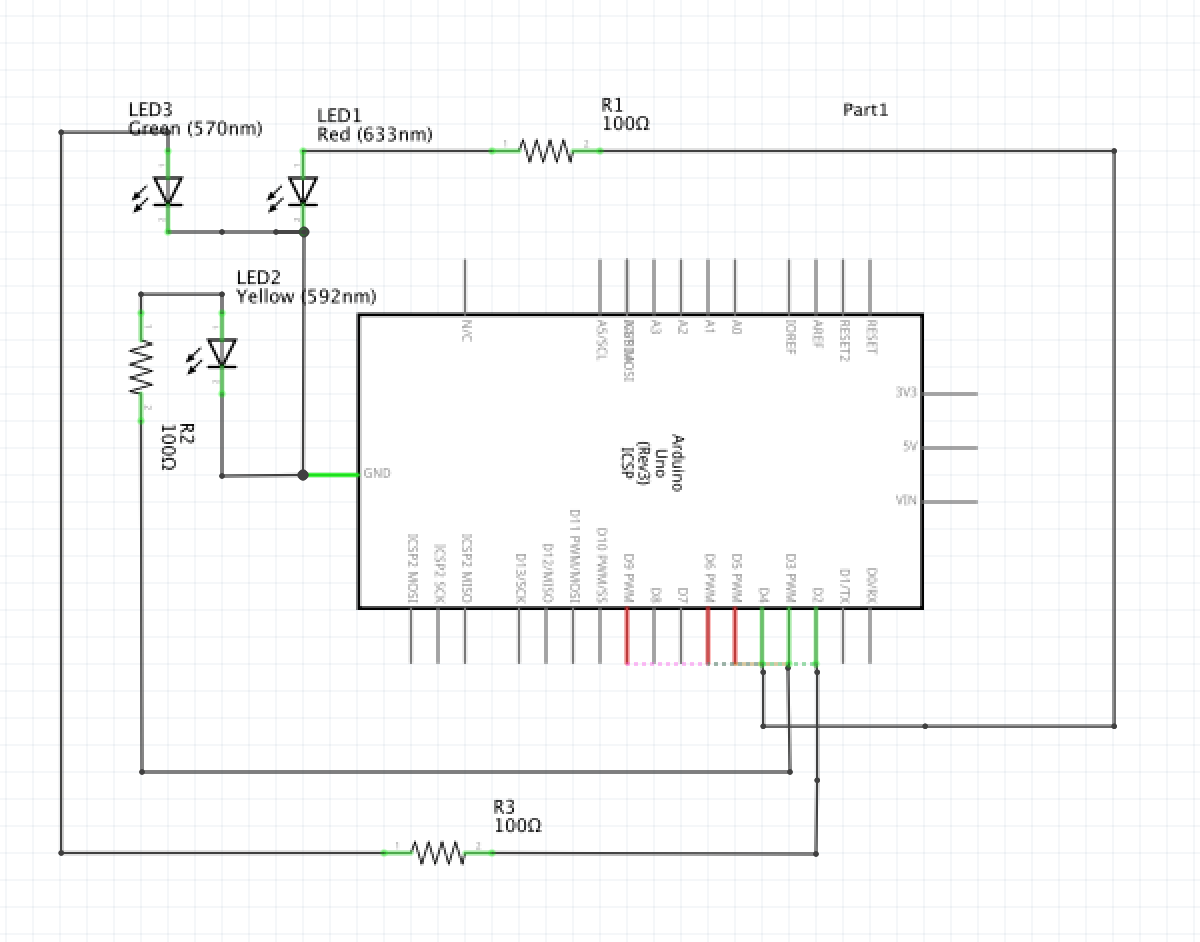
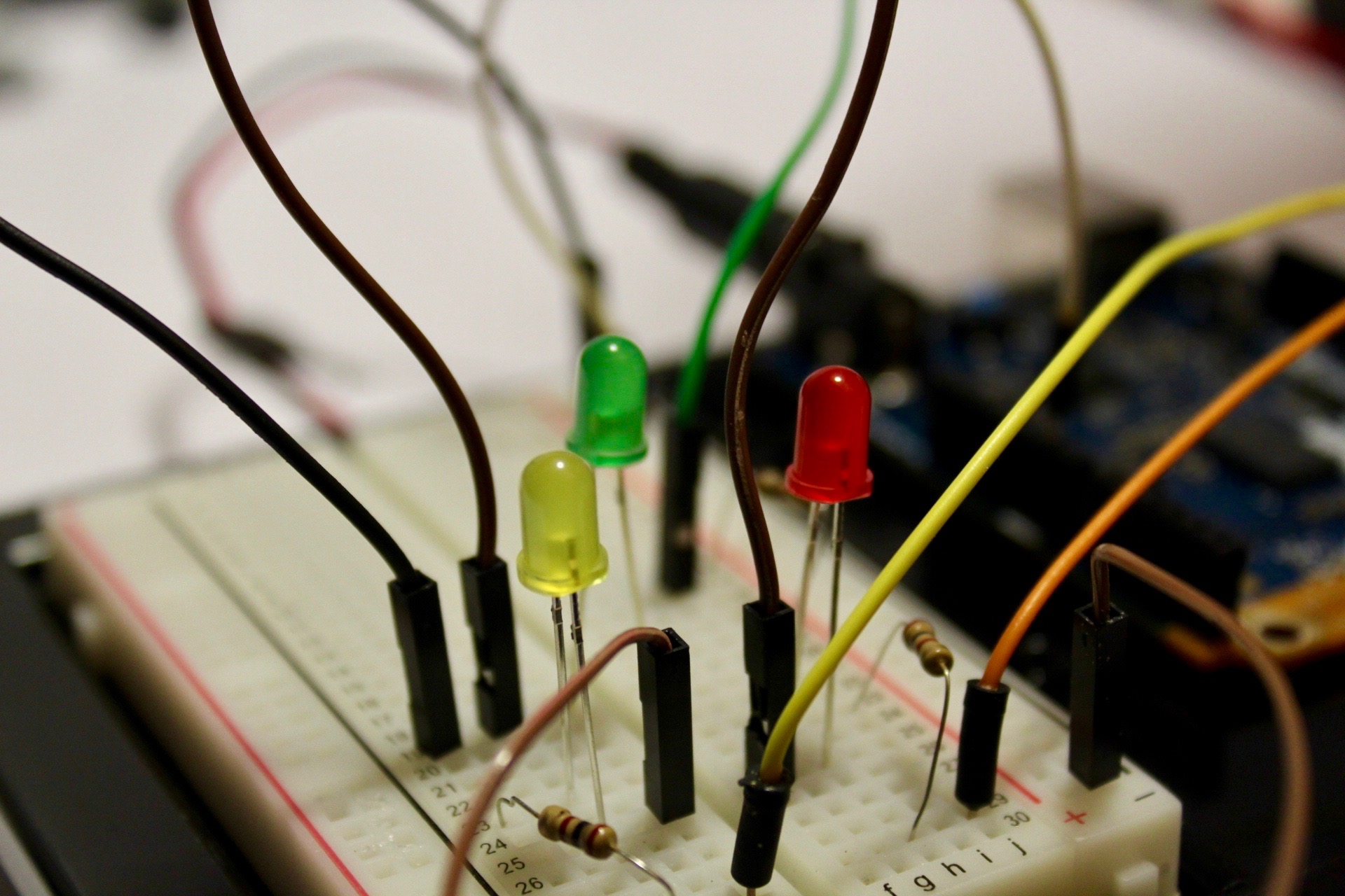
- Connect the cathode (negative pin) of each of the LEDs to the black ground rail on the breadboard.
- Connect the anode (positive pin) of each of the LEDs to a 100Ω resistor.
- Connect the free-end of the 100Ω resistors to the Arduino digital pins in the following order for each of the LEDs.
- Pin 9: Red LED, orange jumper wire
- Pin 5: Yellow LED, yellow jumper wire
- Pin 6: Green LED, green jumper wire
It is important to note that the LEDs be plugged in to PWM pin, marked by a tilda sign on the Arduino board. In addition, the Arduino 101 has less PWM pins than an Arduino Uno, so the same PWN pins that exist on an Arduino may not exist on the Arduino 101.
However, if the brightness control of the LEDs which varies depending on the values gone by the gyroscope is not important for a particular axis, then you may choose to plug it in to any digital Arduino pins..
Coding
#include <CurieIMU>
int ax, ay, az;         // accelerometer values
int gx, gy, gz;         // gyrometer values
int gxBrightness = 0;
int gxLed = 4;
int gyBrightness = 0;
int gyLed = 6;
int gzBrightness = 0;
int gzLed = 5;
void setup(){
pinMode(gxLed, OUTPUT);
pinMode(gyLed, OUTPUT);
pinMode(gzLed, OUTPUT);
CurieIMU.begin();
CurieIMU.autoCalibrateGyroOffset();
CurieIMU.autoCalibrateAccelerometerOffset(X_AXIS, 0);
CurieIMU.autoCalibrateAccelerometerOffset(Y_AXIS, 0);
CurieIMU.autoCalibrateAccelerometerOffset(Z_AXIS, 0);
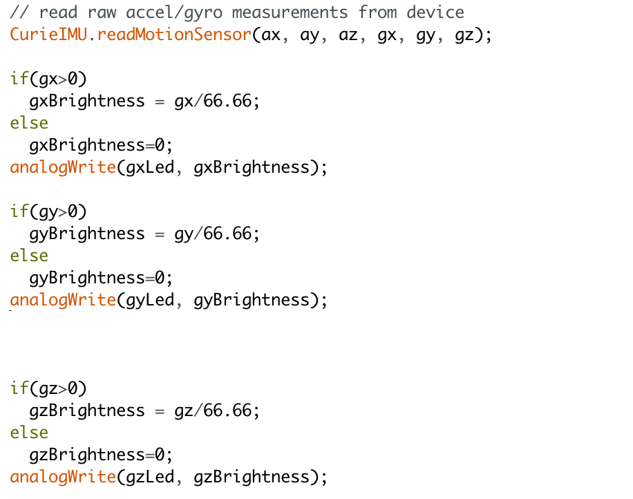
}void loop(){
// read raw accel/gyro measurements from device
CurieIMU.readMotionSensor(ax, ay, az, gx, gy, gz); if(gx>0)
gxBrightness = gx/66.66;
else
gxBrightness=0;
analogWrite(gxLed, gxBrightness); if(gy>0)
gyBrightness = gy/66.66;
else
gyBrightness=0;
analogWrite(gyLed, gyBrightness);
  if(gz>0)
    gzBrightness = gz/66.66;
  else
    gzBrightness=0;
  analogWrite(gzLed, gzBrightness);
}
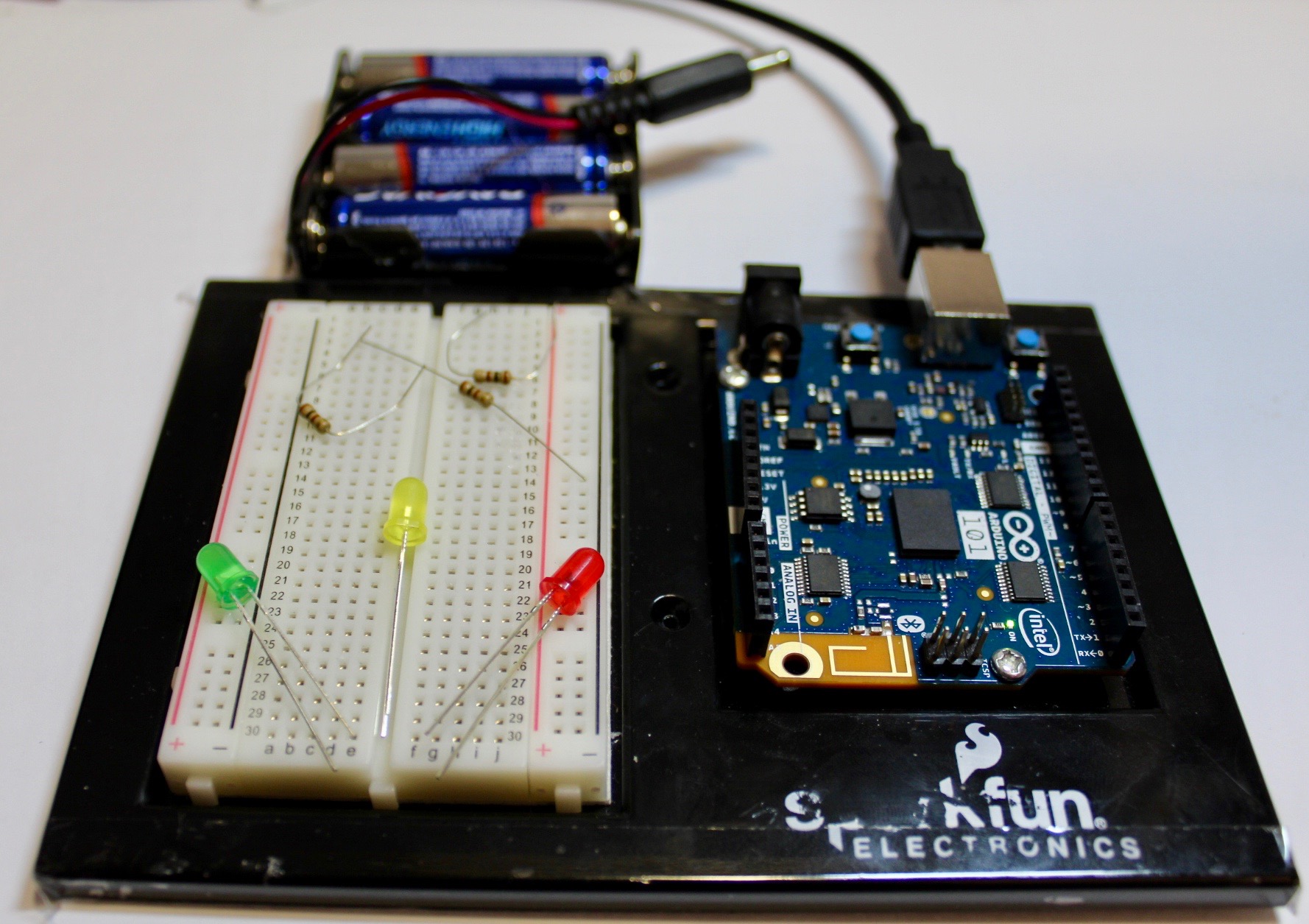
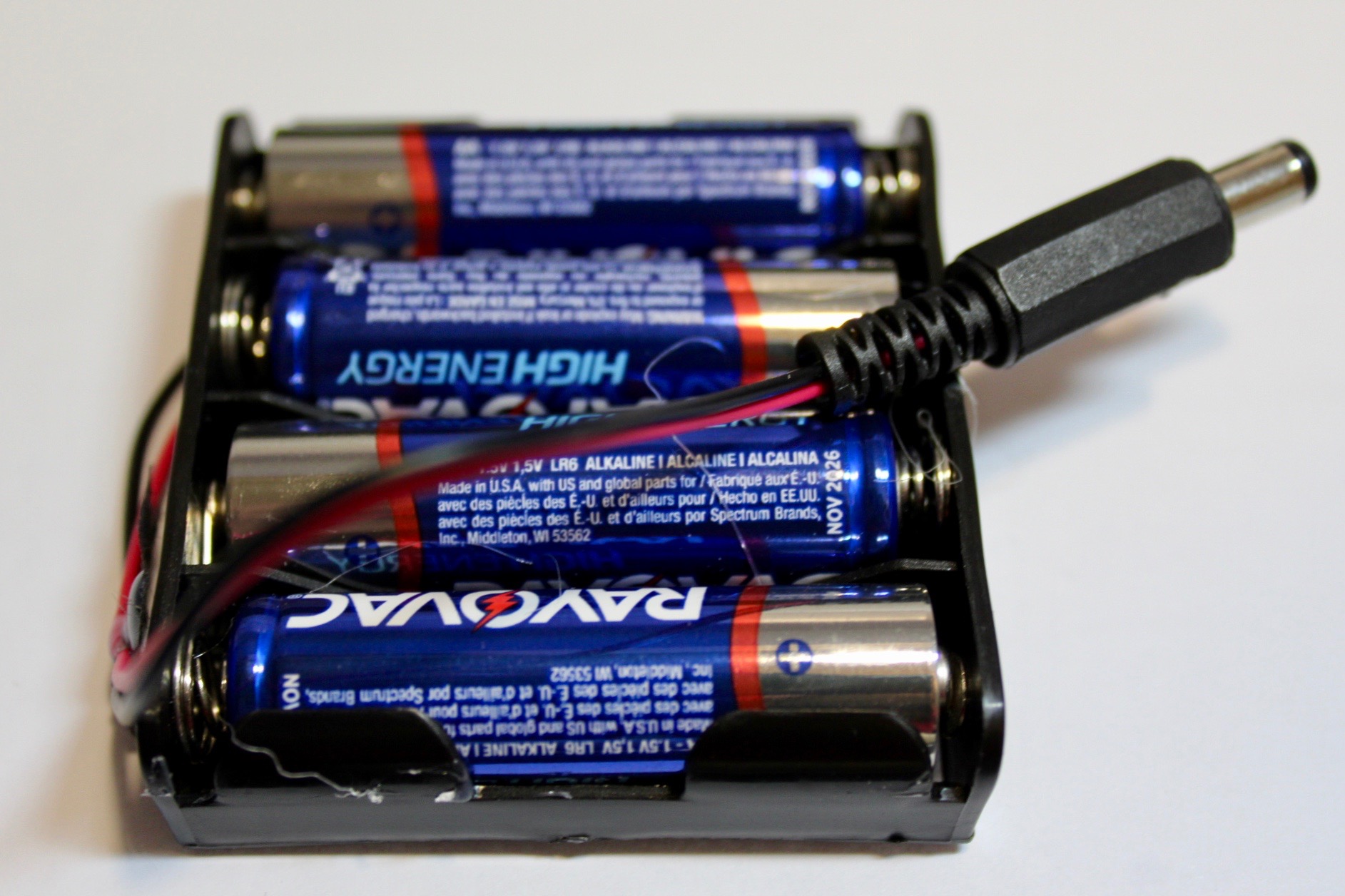
Connect the Battery Pack
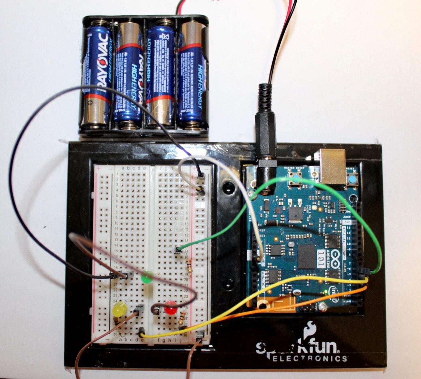
- We will use a battery pack to power the Arduino while the code is stored onto the Curie chip, so that we can freely move around the Arduino without having to worry about cables getting tangled.
- Disconnect the printer cable from the computer to the Arduino
- Connect the barrel jack from the 6V battery pack to the Arduino's port. The LED will light up to indicate it is on.
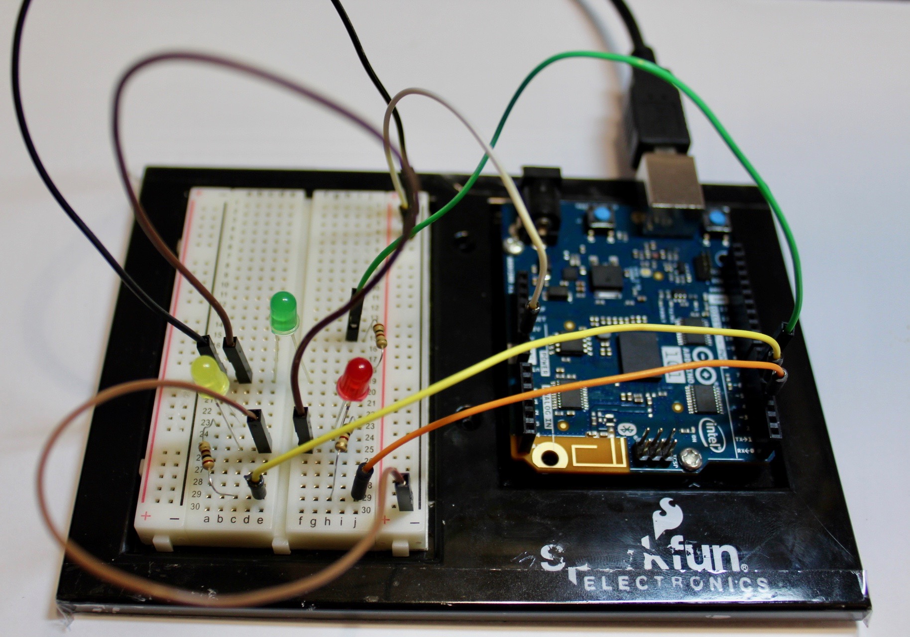
Done!
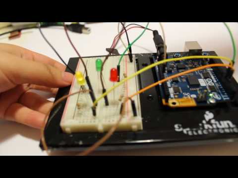
The red LED represents the X-axis. The yellow led represents the Z-axis. And, the green LED represents the Y-axis.