Pier 9 Resource: Setting Up 2D Profiles for CNC in Fusion 360
by scottkildall in Workshop > CNC
3916 Views, 8 Favorites, 0 Comments
Pier 9 Resource: Setting Up 2D Profiles for CNC in Fusion 360
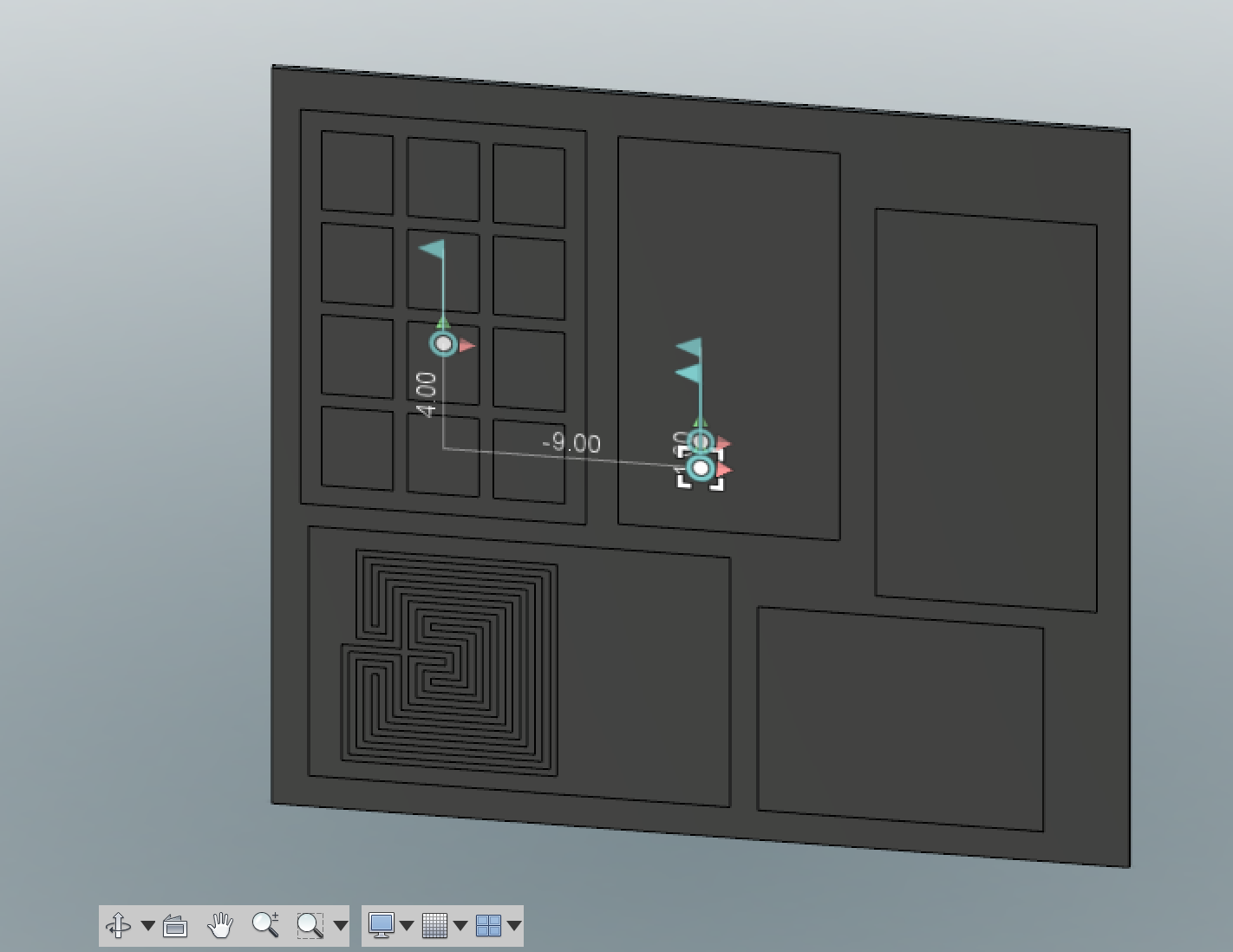
This Instructable is for workshop users at Pier 9, or anyone who wants setup their Fusion 360 parts for cutting on 2.5 axis profiling machines.
Fusion 360 is not only a 3D-modeling program, where you can build virtual 3D models, but it also supports full CAM features. This will let you generate tool paths, run simulations and exporting files specific to certain CNC machines through Fusion 360's CAM environment so that you can build a physical model.
This Instructable will show how to arrange parts of a 3D model in Fusion 360 onto stock so that you can setup tool-pathing on machines such as the OMAX Waterjet, Flow Waterjet, Epilog Lasercutter, Shopbot — or any other machine that will cut and etch/engrave your chosen material.
This Instructable will guide you through the Fusion 360 model environment to prepare for machine-specific post-processing.
Note: In this Instructable, I am using the term etch and engrave interchangeably. These are technically two different processes. An etch means making a line in a surface but not all the way through the material. This is distinct from an engrave process where you would make a pocket in a material. However, the etch or engrave steps will be handled in the CAM environment for a specific machine. This Instructable just covers the Model environment, where the etch or engrave geometry will be handled in exactly the same way.
Launch Fusion 360 With Your Sample Model
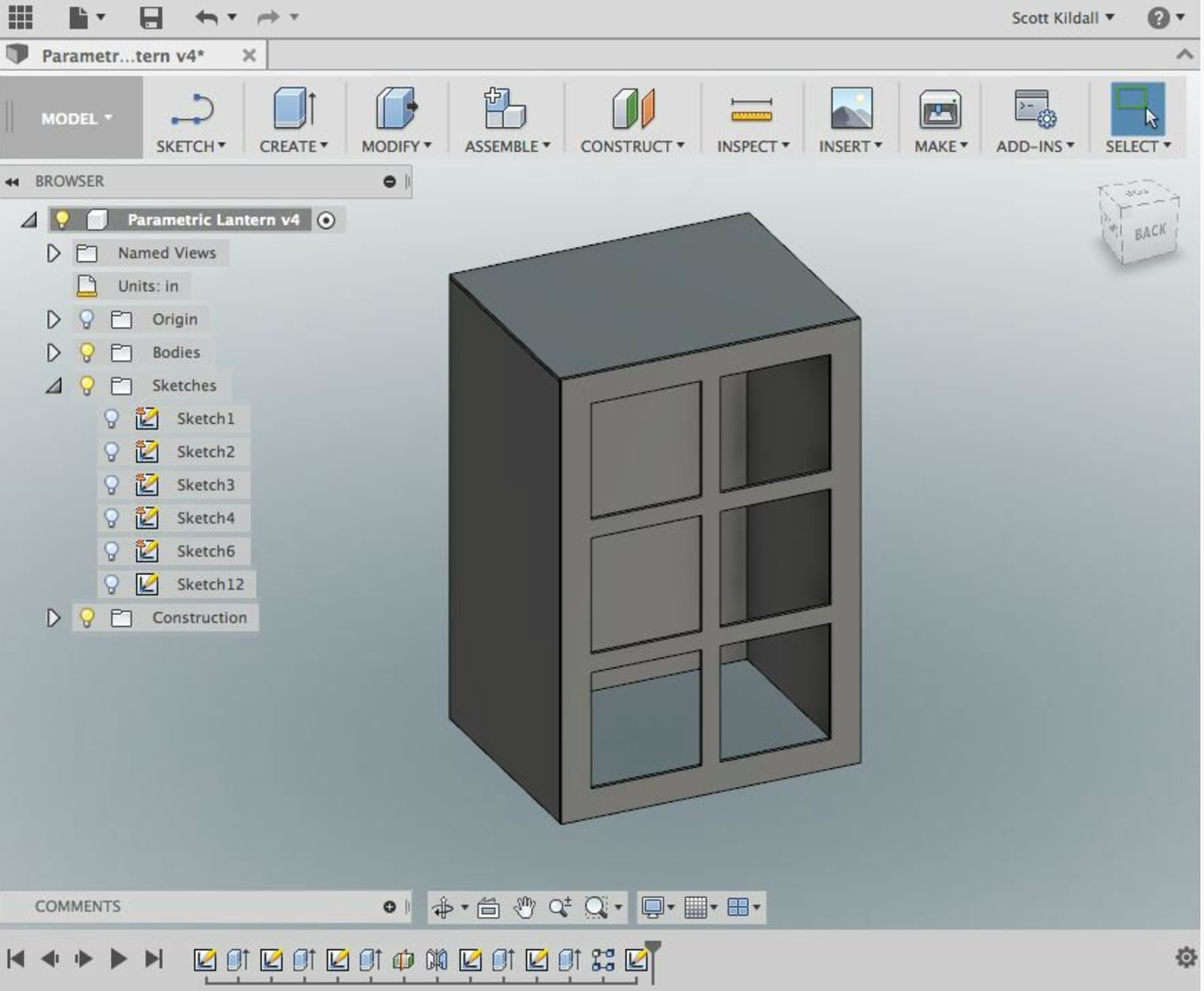
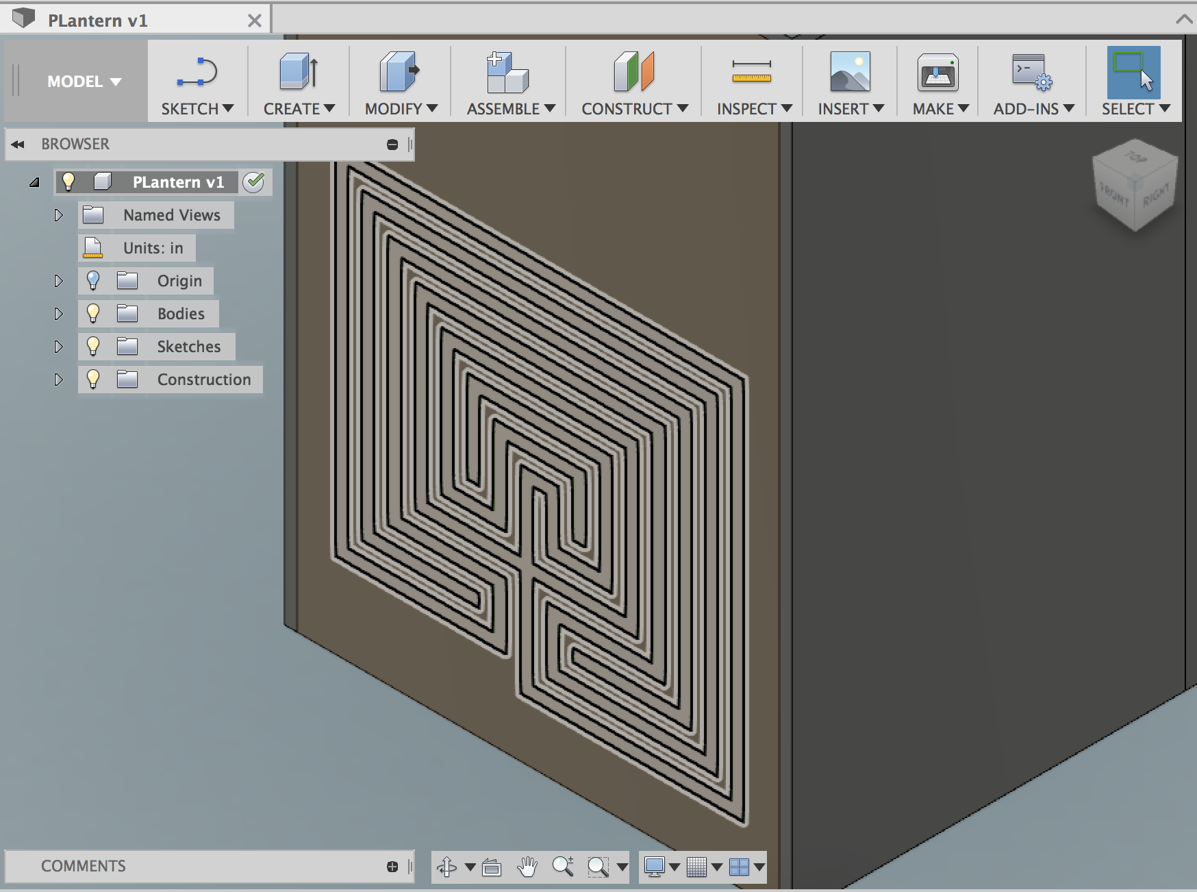
The model that I will be using is one called "Parametric Lantern". It has 5 parts in it that we will want to cut, with an open bottom, 4 rectangular parts and one that looks like a window.
We will also etch/engrave a labyrinth pattern into the back of the model.
The public link to view and download this model is here.
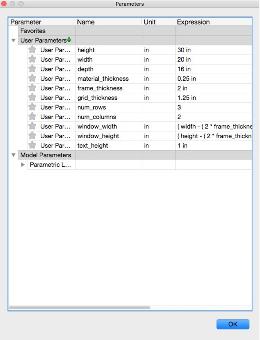
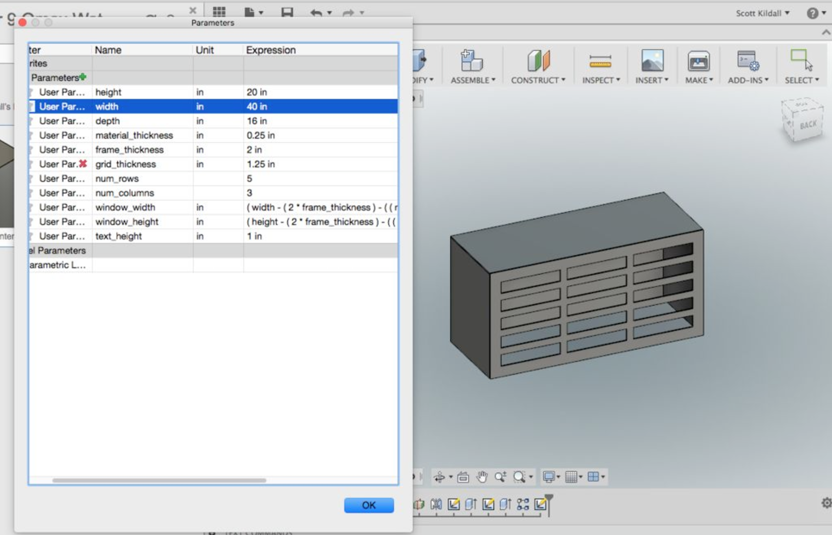
All of the features: length, width, height, window width and other features are parametrically-defined — using variables in the user parameters window rather than absolute numbers for each action. By altering these variables, we can quickly change the look of the lantern.
The parameter that we want to think about ahead of time is the material_thickness parameter, which will be the thickness of the material that we will be cutting on the CNC machine.
Extrude Your Etchings As Geometry
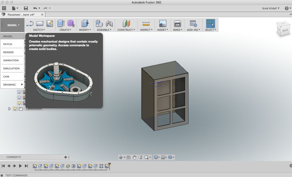
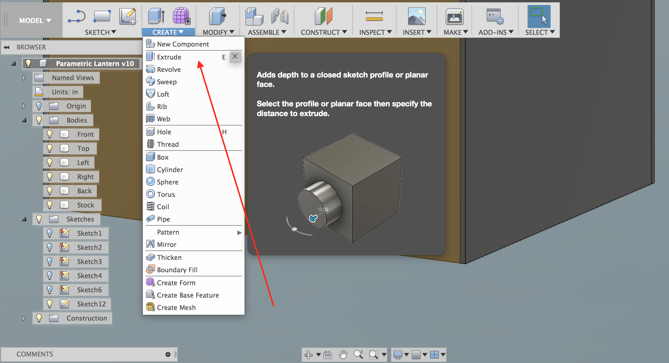
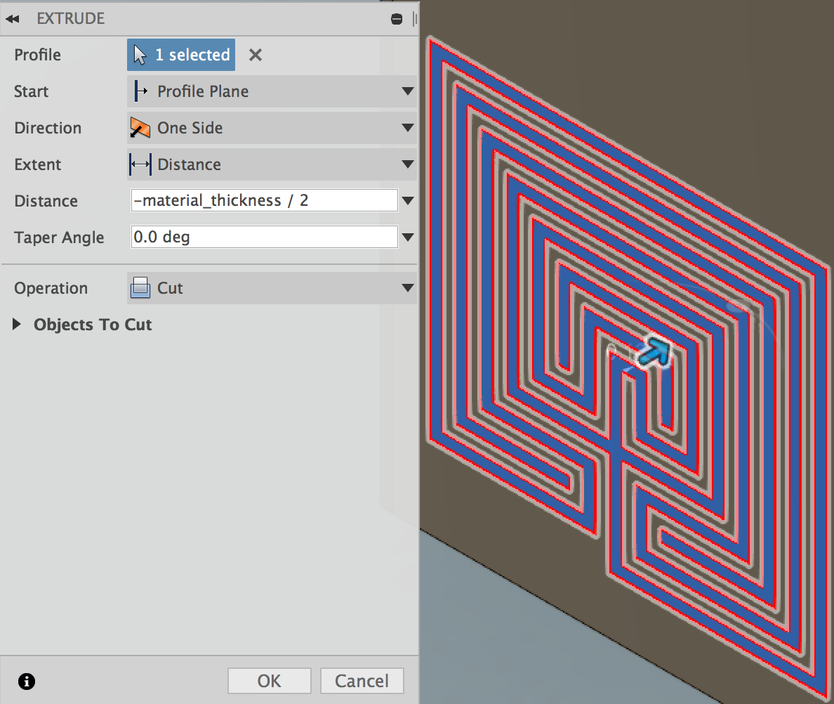
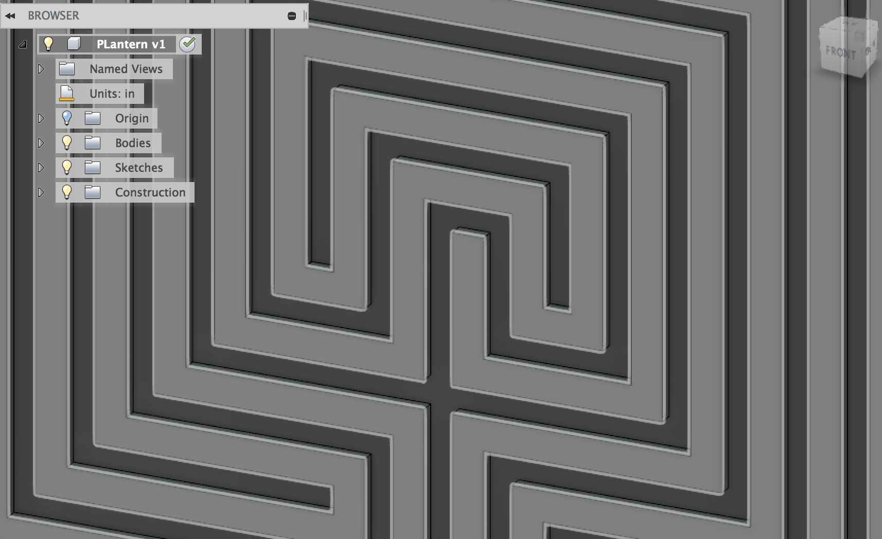
I added a pattern of a maze, which we will etch. In the model, this is Sketch (2D) geometry. We must first extrude this into the material itself to make a new body.
Make sure you are in the model environment by choosing Model from the Workspace menu.
Under the Create menu, choose Extrude (or press 'E'), which will bring up the Extrusion dialog box.
Click on the labyrinth pattern. The distance will be working off the parametrically-defined parameter, material_thickness.
I use the value: -material_thickness/2
This will extrude it into the material, so that it looks etched rather than embossed.
Make sure that under Operation, it says Cut — this will alter the existing body, called Back
Press OK and the inward extrusion will be made. You have now altered the geometry of the back panel with geometry you will end up etching in later steps.
Make Your Stock
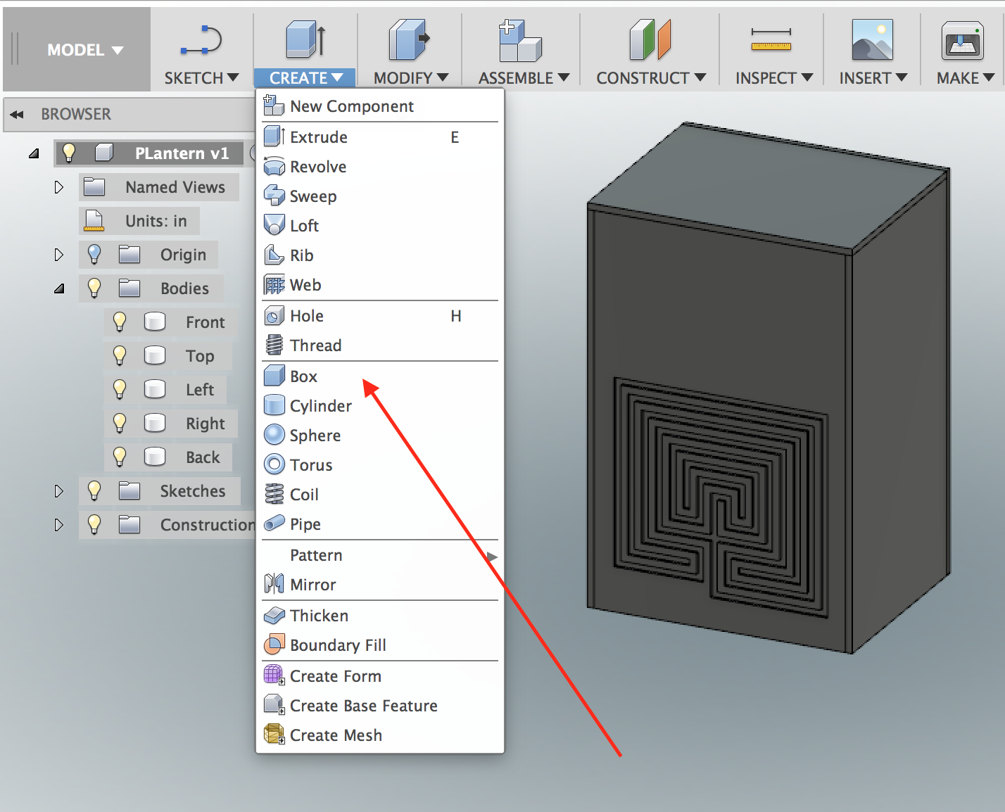
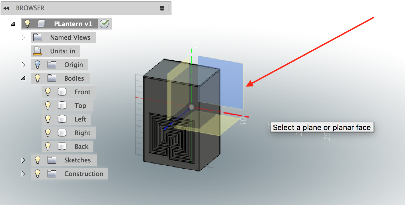
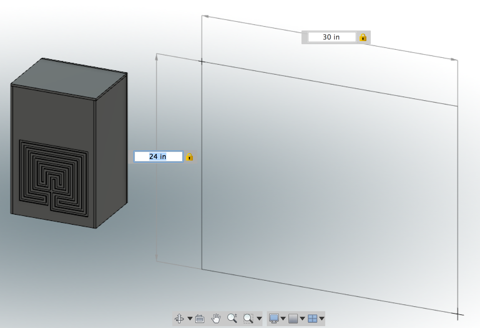
What we will want to do is to lay the parts out flat on a single piece of material, which means that we first have to create a model of the stock we will use.
Zoom out from the closeup of your model.
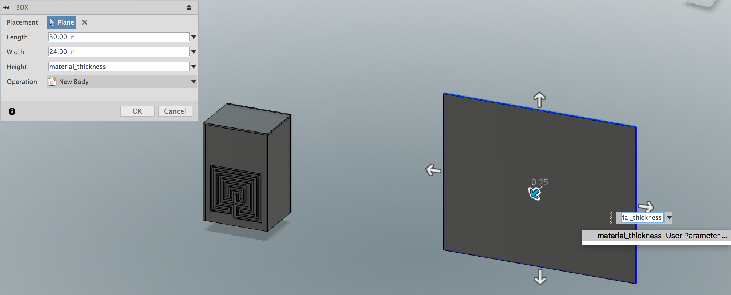
Make a box by choosing the Box menu item from the Create menu.
You want to make this on the X-Y plane (red + green axis). This will be identical to the coordinate system orientation in CAM. You may need to zoom out to be able to select the X-Y axis instead of the parts of your model.
Draw the box away from the model. Type in the width and height of your stock material. We can adjust this later on when we arrange the parts on the stock, so the exact dimensions aren't important at this point.
However, what we want to make sure we do at this point is to make the height of the stock material be set to the material_thickness parameter, which is a parameter we can change when cutting out of different materials.
The idea is that we will be able to use the exact same modeling and CAM output by just changing this one parameter, e.g. the differences between setting up the model and CAM for 1/8" steel and 1" delrin will involve changing just this parameter.
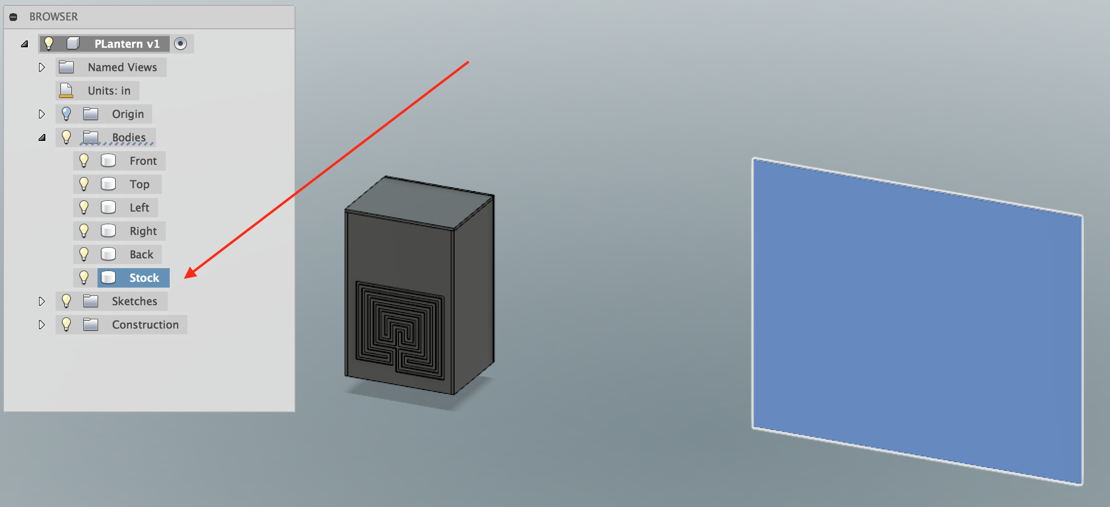
Finally, I rename the body we just created from Body6 to Stock
Make Components From Bodies
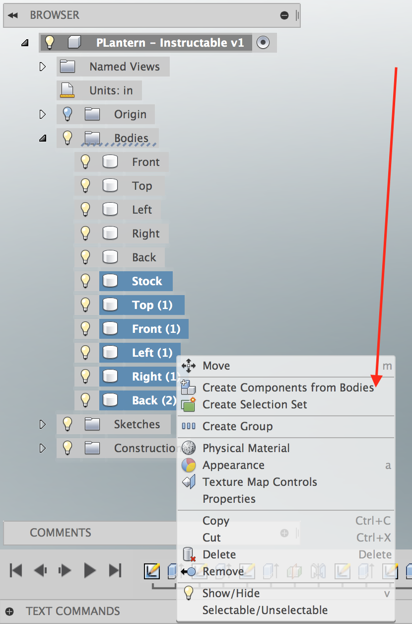
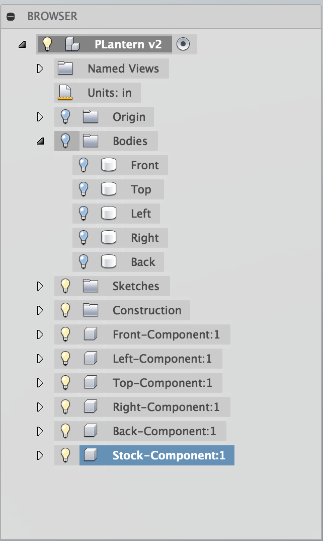
We will want to arrange the parts flat on the stock material before doing any CAM operations.
There are two ways to do this: the first is arranging it manually and the other is to use a scripting solution.
The scripting solution saves time, but I will also show you how to do this by hand. Scripts break and the manual method is tedious, but will work.
In either case, what we will want to first do is to convert the bodies into components.
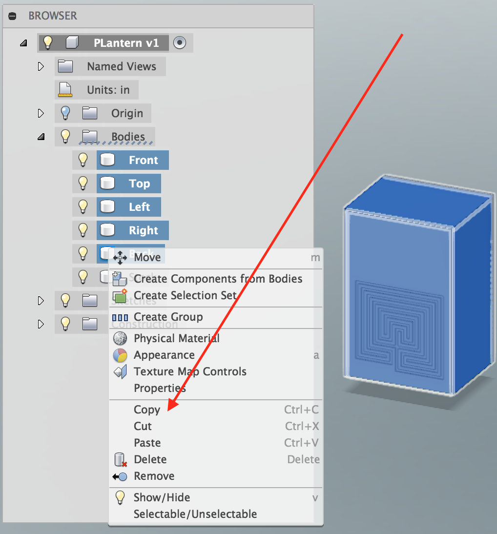
Since I want to keep my original model intact, choose all of the 5 faces (but not the Stock), right-click Copy and then right-click Paste. I don't want to make a copy of the stock as a body, but would prefer to do so with my original model.
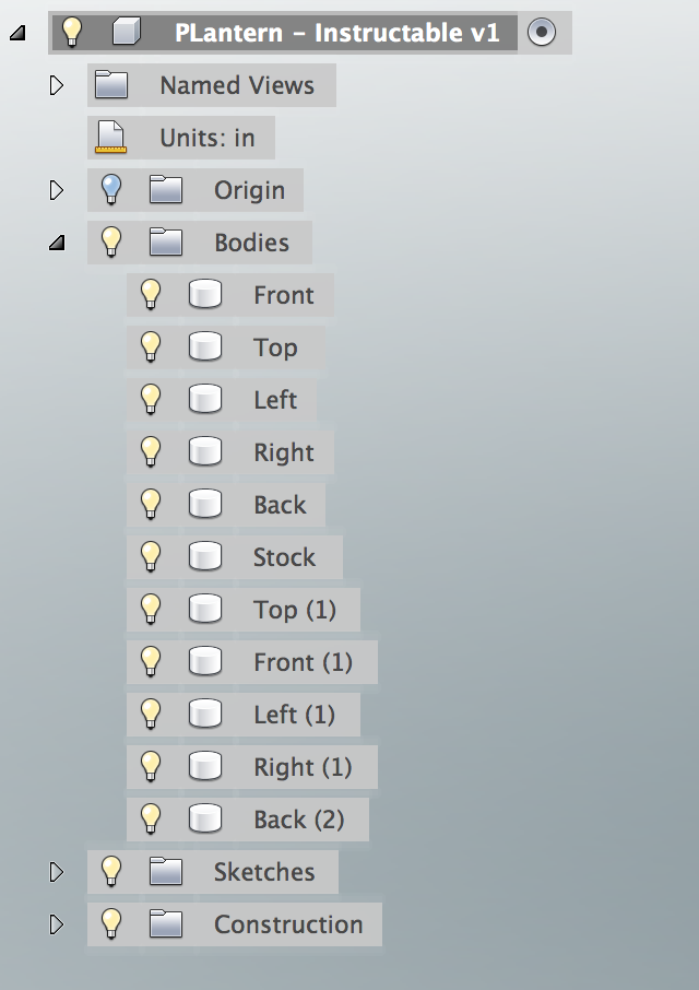
Then, select the newly-created copies of the body, as well as the body called stock, and right-click Create Components from Bodies.
Also, turn off the visibility of all of the bodies so we only see the components.
Note: The components will be called Front (1), Right (1), etc. You can rename these if you wish. There is a name collision if you re-title these to the exact name of the body, so I just use the original name and append "-Component", e.g. "Front-Component", "Right-Component", etc. This way it looks nicer.
Laying Out Components on the Stock (scripting Solution)
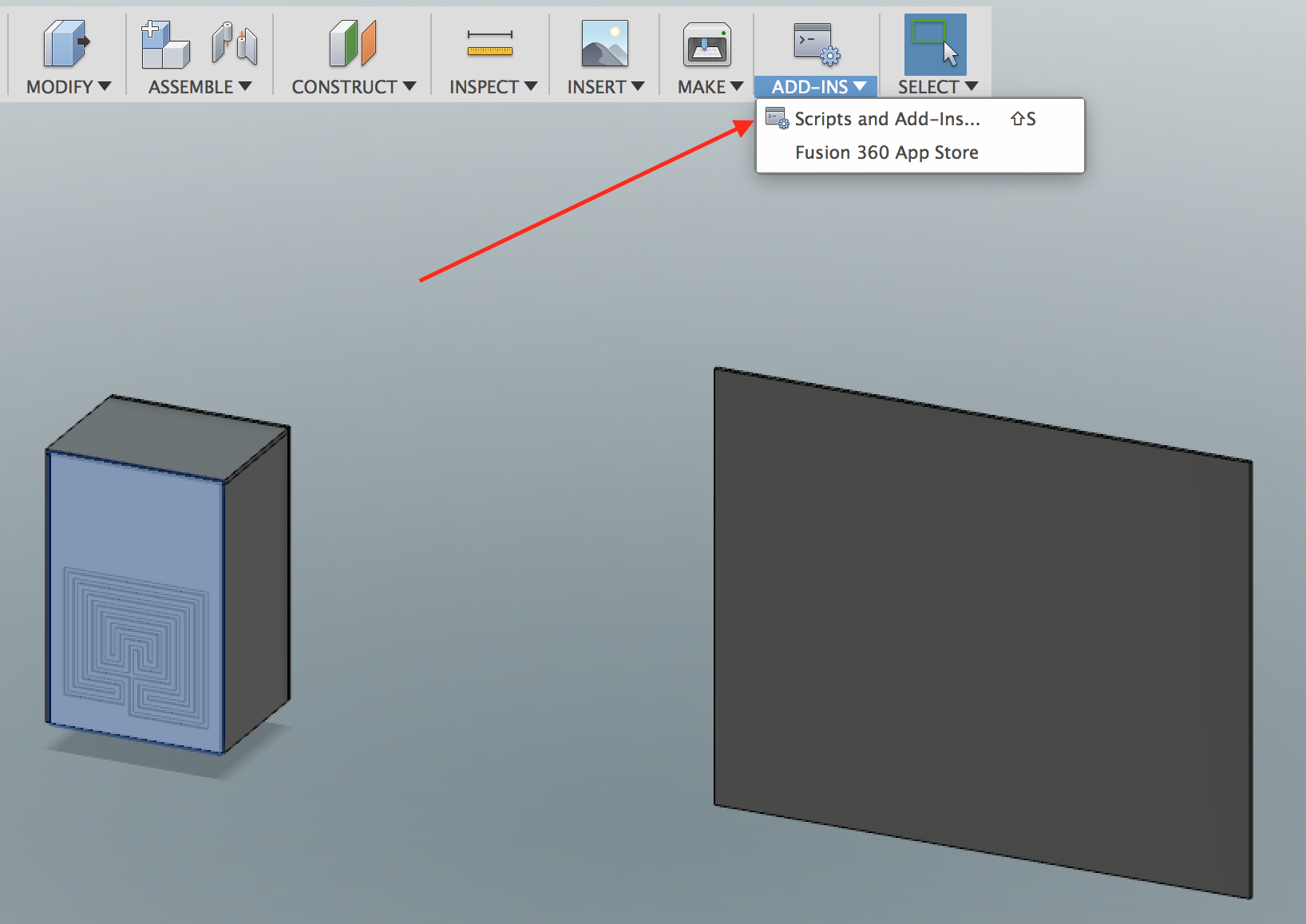
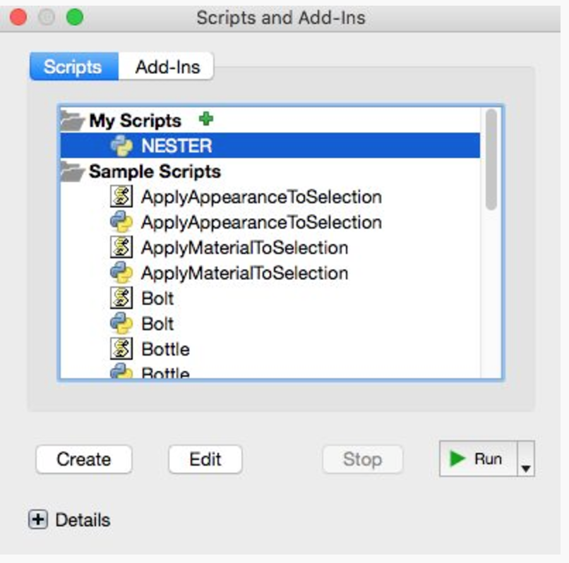
The script we use is called NESTER, created by Patrick Rainsberry. It is one you can download via GitHub, here:
https://github.com/tapnair/NESTER
This video explains how to use the script, in general, but I'll give you an overview below.
Note: This is an unsupported script, so if you have questions, feel free to ask in the comments here. However, please be aware that the script was written by someone else.
Simple Steps for NESTER Script Installation and Use
1. Download Nester from GitHub as a .zip file
2. Change the name of the directory from NESTER-master to NESTER
3. Make sure Fusion 360 is closed. Then copy it into your Fusion scripts directory, following these Instructions
4. From the Add-Ins menu, choose Scripts and Add-Ins. There, you should see NESTER listed as one of your scripts.
Running the NESTER script
1. From the Scripts and Add-Ins dialog box, make sure you have the Scripts tab selected. Select NESTER and press the Run button.
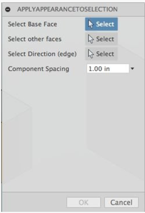
2. Open the APPLY APPEARANCE TO SELECTION dialog box.
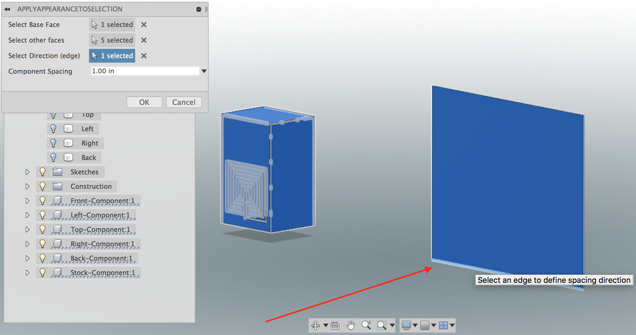
3. Select Base Face should be one of the faces of your stock.
4. Select Other faces, choose the other faces that you want to cut out. In the case of the Parametric Lantern, this will be 5 faces. You can use the navigation cube to scroll around to select each side with your mouse.
5. Select Direction (edge) will be how the faces will be oriented on the surface, i.e. either X or Y (this step is not in the video). I chose the bottom.
6. Component Space is how much space between each component. In my model, this doesn't seem to matter, since in the end my faces are all overlapping on the stock material. We will reposition these later, so leave it at 1.0 in
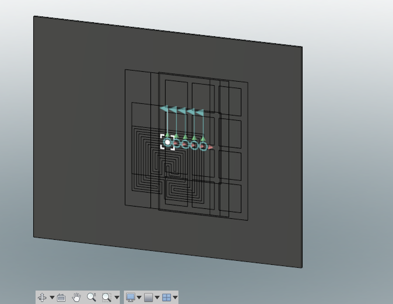
7. Click OK to run the script. After you run NESTER, it will move the selected faces so that they are constrained to be planar with the face of the stock that you selected. All the faces will be a jumbled mess in the center.
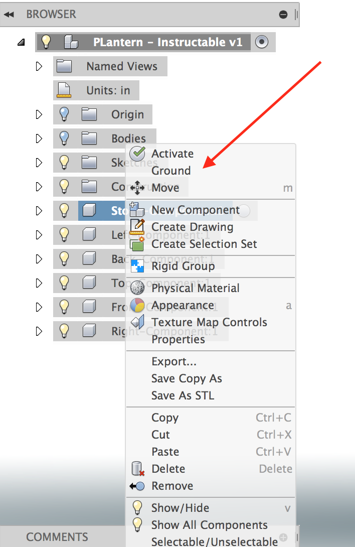
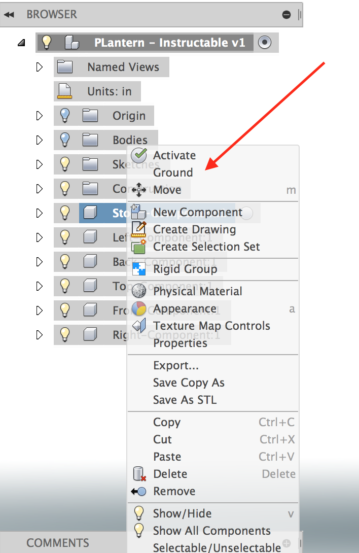
8. Finally, we will want to ground the Stock component, which will prevent it from being moved. Right-click on the Stock component from the hierarchy tree and choose Ground, this will fix it in space
Laying Out Components on the Stock (manual Method)
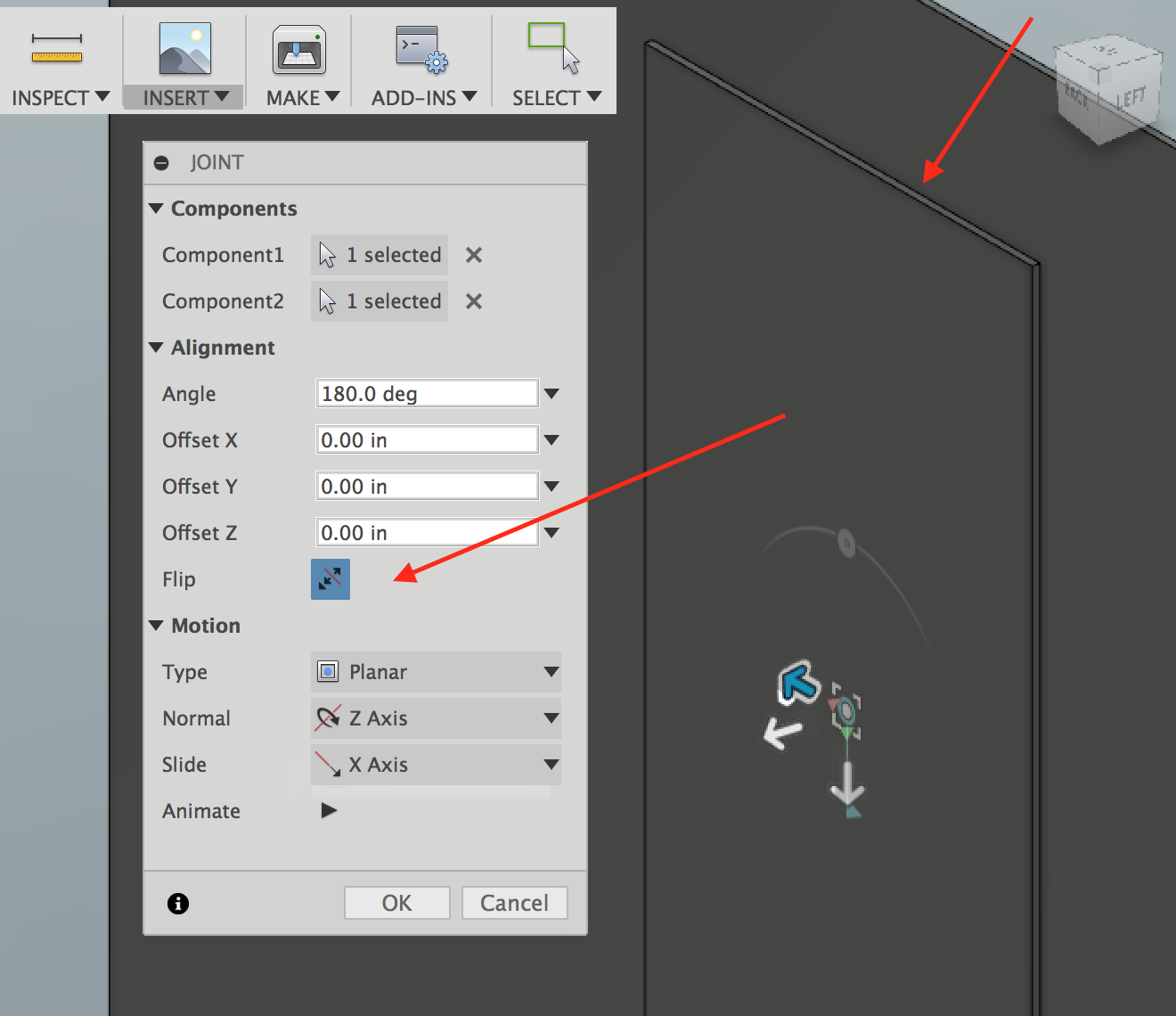
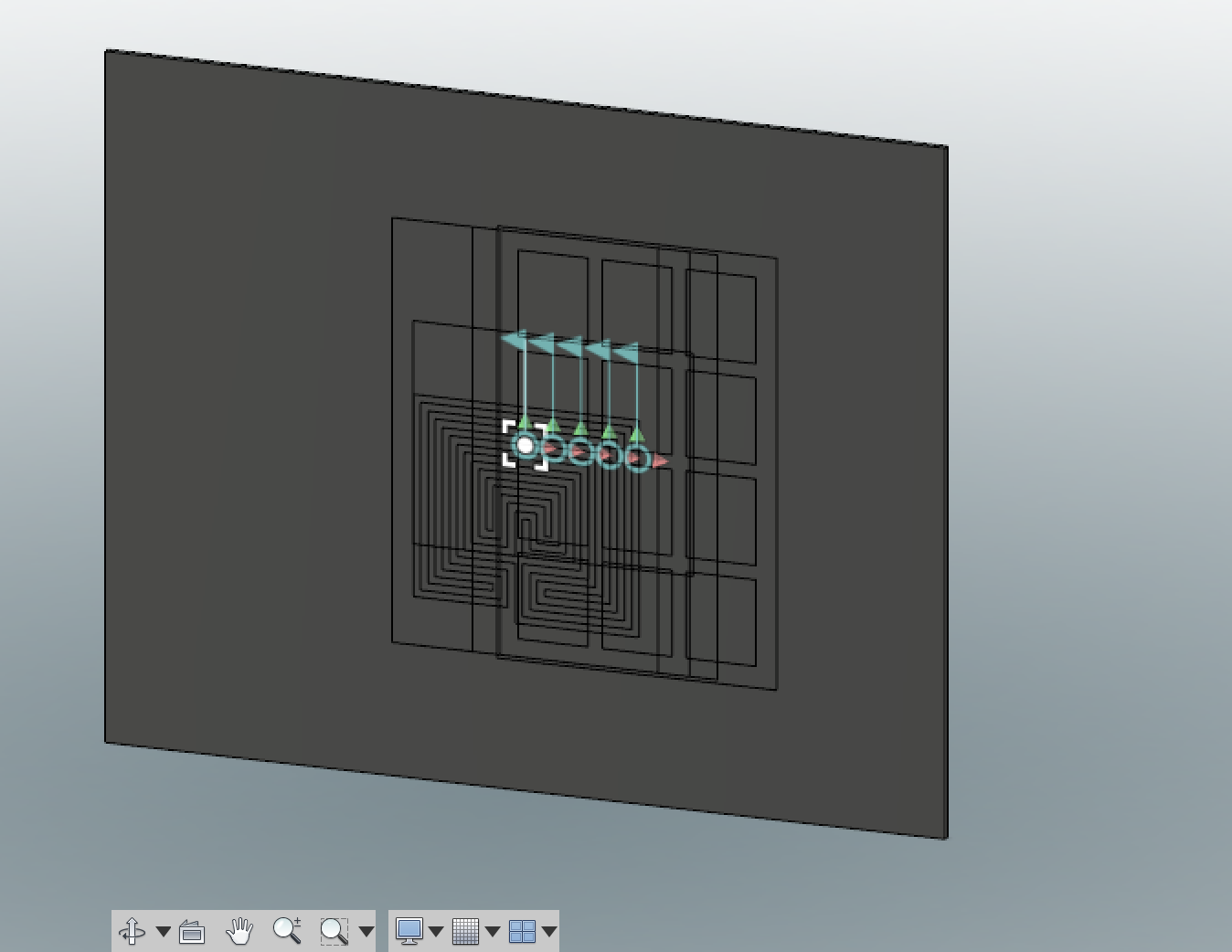
The manual method is certainly more tedious, but if NESTER isn't working for you, you can quickly get your parts arranged on the stock this way.
First, you will want to ground the stock so that it doesn't move. Right-click on the Stock component from the hierarchy menu and choose Ground, this will make it so that the stock will not be a movable item.
Now, for each of the faces, do the following:
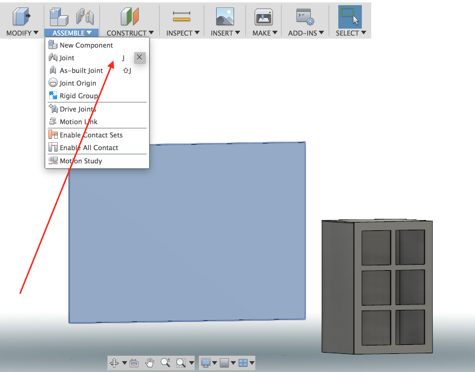
1. Click on the Assemble menu and choose Joint (or press J)
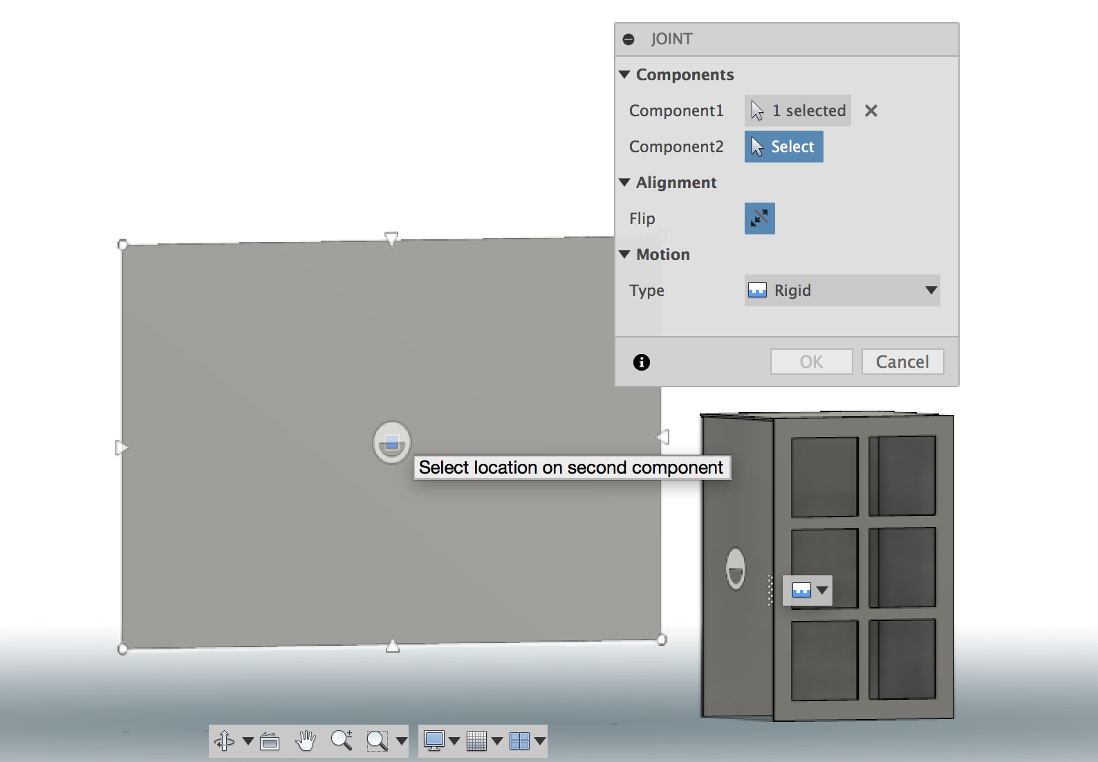
2. For Component 1, choose the midpoint of one of your faces
3. For Component 2, choose the midpoint of the stock, this will move the component on top of the stock with a silly animation. It positions your face onto the stock
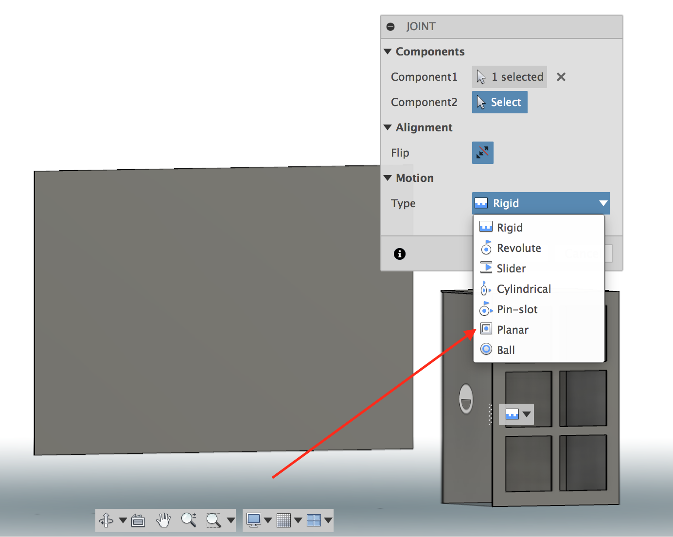
4. In the Motion area, choose Planar for Type. This will restrict the movement to the plane of the stock
5. Now, zoom in on the stock and look to see if the component is on top of the stock or inside of the stock. We want it inside of the stock. If it is protruding on the top of the stock (like the image here), press the Flip button and it will reposition your component into the stock. Press OK and the face will be in the center of the stock.
Note: Though not necessary, I found it easier to turn off the visibility of each component after I placed it on the stock. It is trickier to see what you're doing when there are many items on the same selection area. Then, when done with all the placements, turn the visibility of all of them back on.
After we do this for each face, all parts will be positioned in the center of your stock
Arranging Parts on the Stock
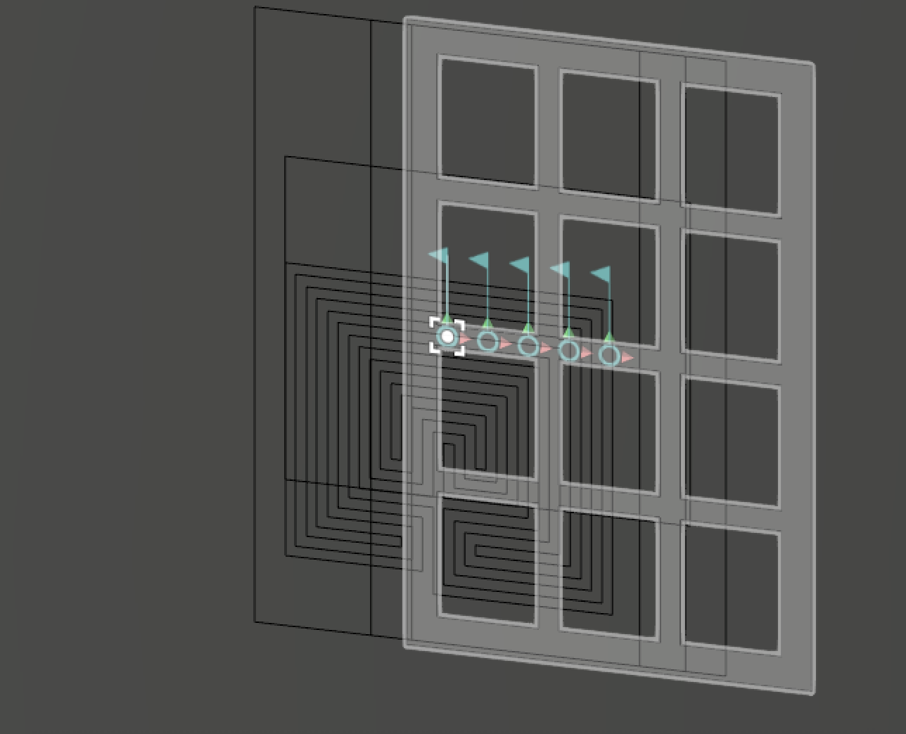
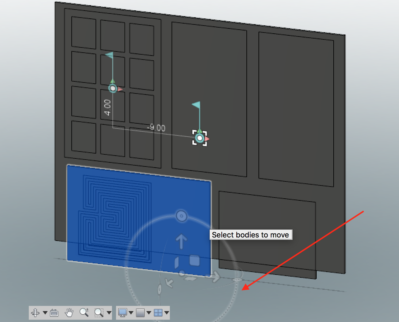
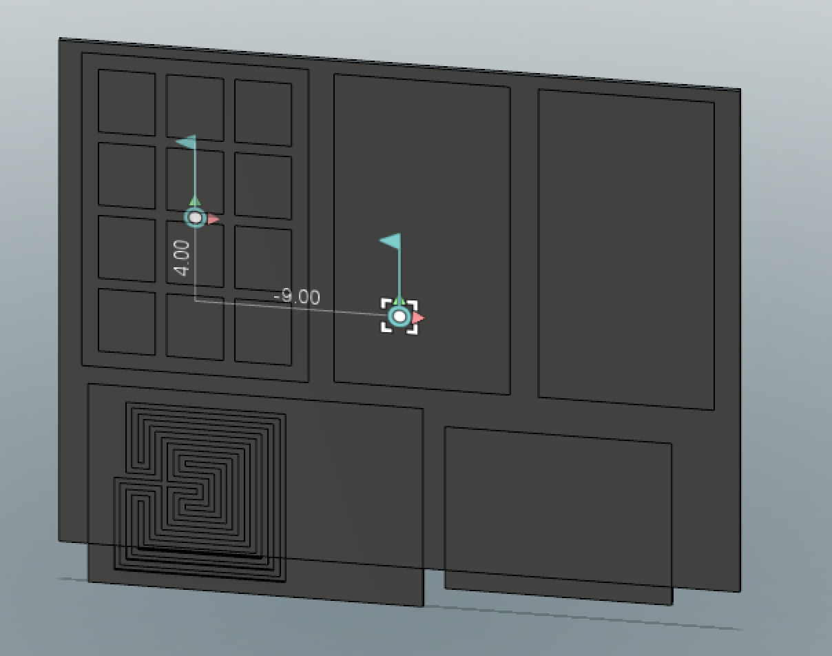
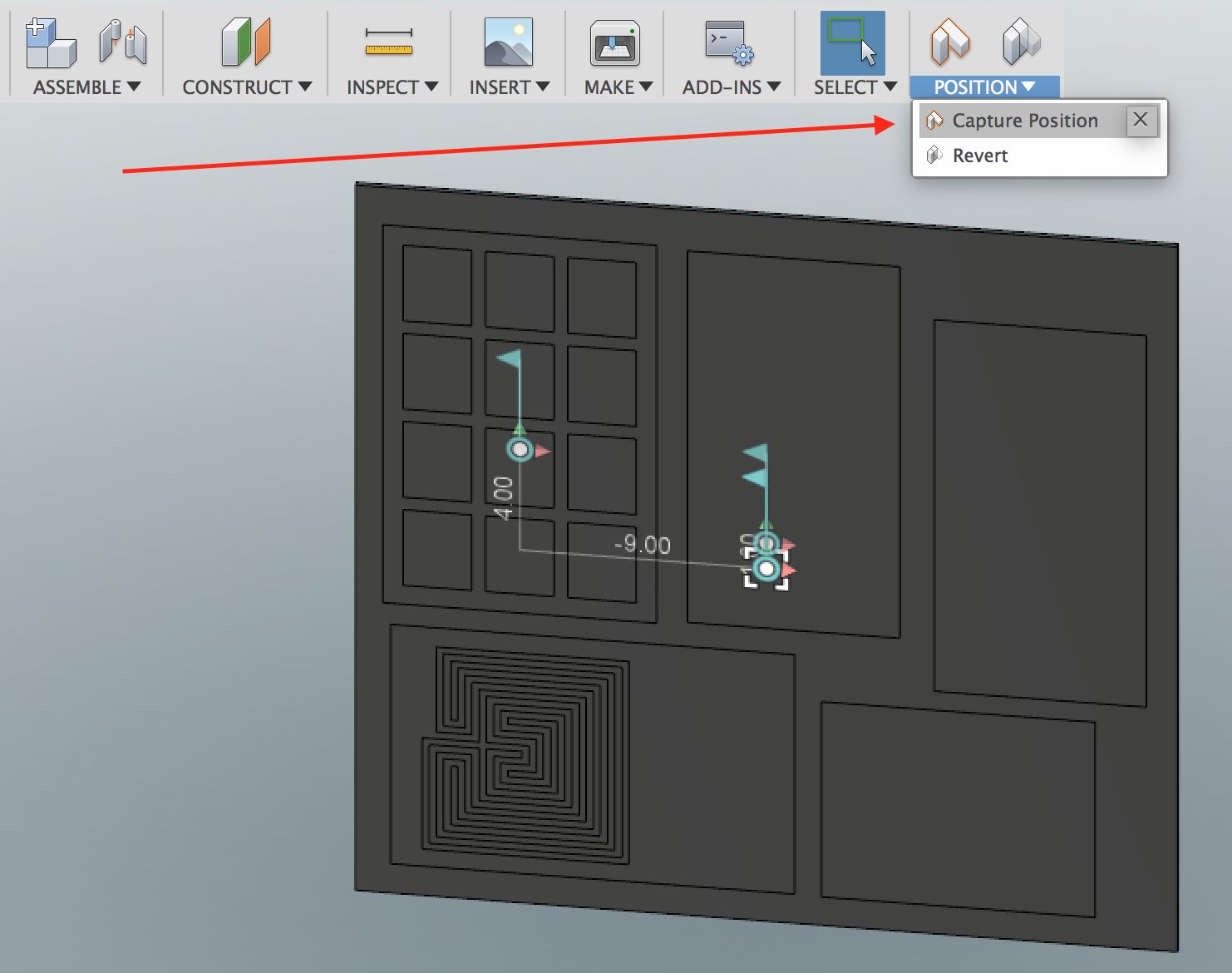
Now, we will reposition the parts manually on the stock by clicking and dragging on each component. Hover the mouse over the faces and you will see an individual face get highlighted. Now you can just click on the face and drag it to a new position on the stock.
They may not fit on the stock, so you can do two things to fix this: either rotate the components or enlarge the stock size. And, you may need to do both.
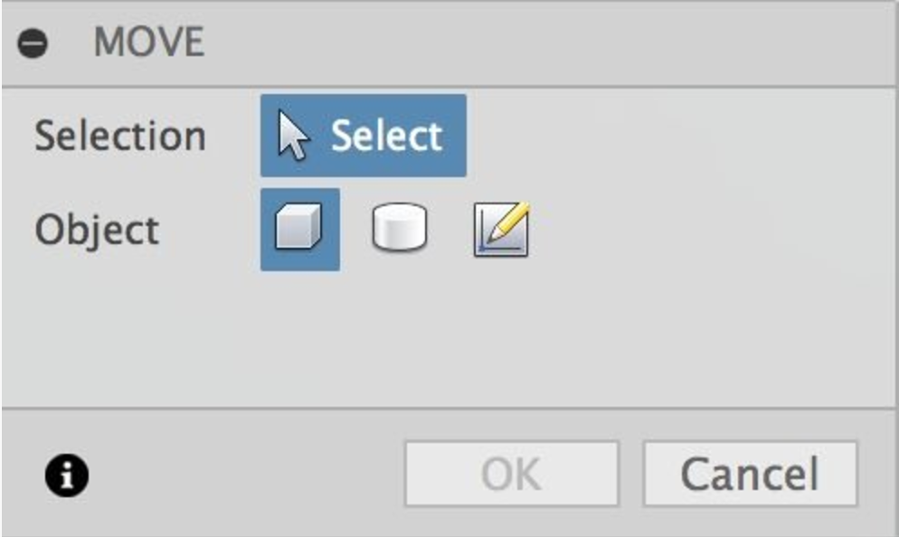
1. To rotate, from the Modify menu, choose Move (or press M on the keyboard) At the Move dialog, under Object, select Move Components. Select the face you want to rotate and use the rotation circle to rotate it. You may need to use the navigation cube to get the a good viewpoint for the selecting the rotation circle that is planar to the stock.
Press OK to enact the rotation.
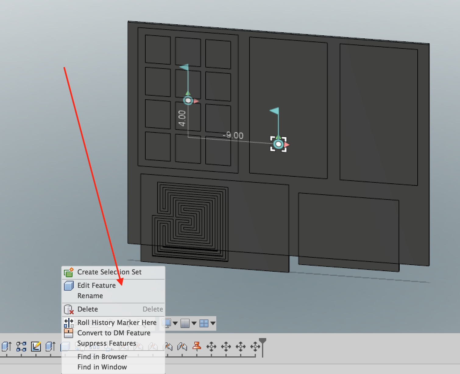
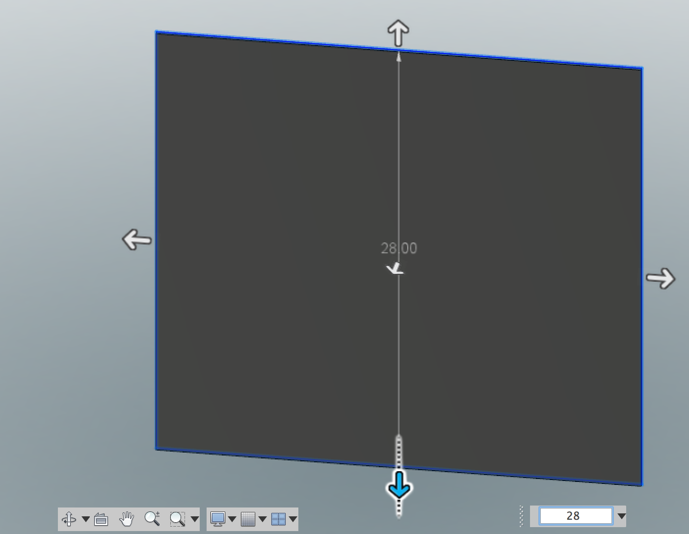
2. There are several ways to change the stock size. My preferred method is to select the Make Box action on the timeline, right-click and choose Edit Feature. Now, you can make a larger stock size.
Important: Position your items close to the lower-left of your stock. This will be our origin point for doing the cutting.
All of the faces should be in the stock. It's also okay if the stock is much larger than the items, since it is virtual stock — we are not bound to these constraints when doing the actual cutting, i.e. the stock geometry never gets exported. You can continue to do some more moving of the parts to get the parts optimally-positioned on your material.
Note: When you are done, you can capture your current position, by selecting from the Position menu, Capture Position. This will add a feature to the timeline, so that you can go back to that position.
Done!
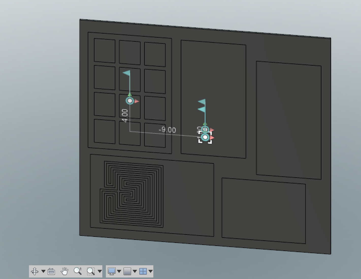
At this point, your parts are ready for 2D CAM work. The specific steps for each machine will be slightly different. This general-purpose Instructable will set you up so that you can run out your tool-pathing in the CAM environment and export specific file using post-processors for the specific machine.