Semi-Autonomous Garden Watering System
by Disguised-Coffee in Circuits > Microcontrollers
269 Views, 3 Favorites, 0 Comments
Semi-Autonomous Garden Watering System
![Project Semi-Autonomous Garden Watering System [Reupload]](/proxy/?url=https://content.instructables.com/F94/0JXR/LPB7EFG5/F940JXRLPB7EFG5.jpg&filename=Project Semi-Autonomous Garden Watering System [Reupload])
One of the greatest problems of a student garden hobbyist is remembering to water plants, as the average student gets busy with exams, homework, etc. This is especially true in the case of having an entire grocery-store-sized shelf’s worth of plants. One of the easiest ways to mitigate this problem is just to have self-watering pots with water reservoirs. However, this is hard to achieve for plants already fitted with traditional garden pots, especially potted house plants. So rather than watering a plant every day, why not use a microcontroller to water for you?
If you’re uninterested in the coding process, my code can be found on GitHub at https://github.com/Disguised-Coffee/project-SaGWS
Supplies

- Particle Argon
- Breadboard
- Low torque potentiometer
- Soil humidity sensor
- Submersible pump
- SRD-05VDC-SL-C 1 way relay with breakout board
- 1 Gallon Ice Cream bucket
- 2 Water bottles (Ideally, one as an 8 oz bottle)
- Scrap plywood (HIGHLY ADVISED NOT USING, use plastic or acrylic instead)
- Yarn
- Hot glue
- Cardboard
- Painters Tape
- Marker
- Clear plastic lid
- A pot with dry soil
- A freshly watered pot of soil or plant
- A brightly lit area (or a giant indoor garden setup)
- A laptop with a USB port and is serial monitor capable
- A long USB cable and an AC to USB adapter
- Wooden floor shim (or wooden stake)
- Alligator clips
- Male to female jumper wires
- Male to Male jumper wires
- Box knife
- Scissors
Optional:
- Pot of soil
- Seeds
- Soldering wire
- Soldering station
- Heat shrink
- 12 Gauge wires
- Wire strippers
- Hack Saw
Setup Soil Sensor

- After setting up your Particle Argon and placing it within the breadboard, setup male to male jumper wires from the VUSB port to the positive terminal of the breadboard and GND to the negative terminal.
- In terms of the soil sensor, using the male to male jumper cables, the signal pin wire to the A0 port, the 5V power to D2 port, and the GND to one of the GND terminals.
- Instead of using power from the 5V terminal, you’ll need to place the power on a port as powering the soil sensor deteriorates the sensor slowly over time due to the reactions between electricity, metal, and water.
- Codewise, you’ll need to add the following:
//This is Arduino code, which is based on C/C++

#define ADC_PIN_ONE A0     // Analog inputs
#define SOIL_SENS_PWR_ONE D2 // so that soil sensor doesn't ware out as quickly.

//In setup()
...
pinMode(SOIL_SENS_PWR_ONE, OUTPUT);    // Set pin used to power sensor as output
digitalWrite(SOIL_SENS_PWR_ONE, LOW);  //Ensure that this is off
...

// Gets soil Humidity from sensor.
int readSoilHumidity(){
    return analogRead(ADC_PIN_ONE);
}

//Soil Sensor power
void turnOnSoilSensPwr(){
    digitalWrite(SOIL_SENS_PWR_ONE, HIGH);
}

void turnOffSoilSensPwr(){
    digitalWrite(SOIL_SENS_PWR_ONE, LOW);
}
For clarification, setup() runs once upon startup and loop() runs after setup until the microcontroller is either reset or powered off.
readSoilHumidity() reads and returns the voltage from the signal pin of the soil sensor based of the values of 0 to 4095 using the function analogRead()
Setup Water Pump (and Relay)

If you are using the same breakout board as me, you will need to utilize the 3.3V output from the argon to properly use the relay.
- Use the D3 port for the signal and GND to GND terminal.
- From your water pump, have one wire from the positive side of the pump go to NO (Normally Open) and the other wired to the breadboard. Have another wire from the positive terminal to the CO port of the relay.
- If you have another 3.3-5V power source, power the wires from the pump instead of the breadboard, as this will lower the chances of your microcontroller from being shorted.
- In terms of testing the relay, use the following code:
- Make sure you plug in your USB from your Argon into your PC and use a Serial monitor!
(Coolterm or a VSCode extension should work)
#define RELAY_PIN_ONE D3 //Pump 1

// the setup function runs once when you press reset or power the board
void setup() {
  // initialize digital pin as an output.
  pinMode(RELAY_PIN, OUTPUT);
  Serial.begin(9600);
}

// the loop function runs over and over again forever
void loop() {
  Serial.println("Turning on...");
  digitalWrite(RELAY_PIN, LOW);
  delay(500);
  Serial.println("Turning off...");
  digitalWrite(RELAY_PIN, HIGH);
  delay(500);
}
In terms of the project, you’ll want to add this code:
#define RELAY_PIN_ONE D3 //Pump 1

//In setup()
...

pinmode(RELAY_PIN_ONE,OUTPUT);

digitalWrite(RELAY_PIN_ONE, HIGH);
...

//Relay Signal Pin
void startPump(){
    sop("Watering...");
    digitalWrite(RELAY_PIN_ONE, LOW);
}

void stopPump(){
    sop("Stopping water");
    digitalWrite(RELAY_PIN_ONE, HIGH);
}
Setup Potentiometer

Using Alligator clips and the male to male jumper wires:
- Connect an Alligator clip to the left side of the potentiometer and connect the end to a male jumper wire. With the end of that male jumper wire, connect that wire to any part of the positive rail.
- Do the same exact thing for the right side of the potentiometer, except place the male end on the negative rail.
- Then do the same thing except place the wire into the A1 port from the Argon.
- Ensure that left or right Alligator clips are not touching the middle alligator clip, as it will influence the voltage value from the potentiometer.
All of this can also be done with soldering wires to the potentiometer and running them to the breadboard.
#define WATER_LEVEL_SENS A1 //POT

// Reads value from potentiometer sensor
int readWaterLevel(){
  return analogRead(WATER_LEVEL_SENS);
}
Program It All Together!
This is the logic of the project:
- Is the soil humidity wet enough to water after a few hours?
- If no, check again later
- If Yes, figure out if the whole system is working properly to water
- If the whole system is working, start watering session and upon ending the watering session,
- If the water level isn’t enough, don’t water at all.
- If the water level is enough, but the soil sensors don’t work, water only for a time limit
- Send feedback upon finishing
Watering values are needed, so in your global variables (defines):
//Soil Sensor Constants:
//Note: Particle is different from Arduino, and these values vary,
//      as power draw does affect the soil sensors
#define DRY_SOIL 2033
#define WET_SOIL 1500
To periodically check soil humidity:
void loop() {
  // every 2 hours, or so, check for watering.
  if(checkTime(2) && (basicSoilSensTest() > DRY_SOIL)){
    waterTheFlowers();
  }
  delay(2000);
}
This means we’ll need both a timer, and a function returning the analog humidity value.
//Less power intesive test.
int basicSoilSensTest()
{
  digitalWrite(SOIL_SENS_PWR_ONE, HIGH);       // Turn sensor power on
  delay(10000);                      // Allow circuit time to settle
  int val_ADC = analogRead(ADC_PIN_ONE); // Read analog value from sensor
  delay(100);                        // Small delay probably not needed (going to leave this for now)
  digitalWrite(SOIL_SENS_PWR_ONE, LOW);        // Turn sensor power off
  return val_ADC;                    // Return analog moisture value
}

...

// Time checker.
int currentTime;

void setLastTimeSinceWater()
{
    currentTime = Time.now();
}

/**
 * Checks time if time is greater than specified hours
*/
bool checkTime(int hours){
    return Time.hour(Time.now() - currentTime) >= hours;
}
In our watering function:
//in setup()
...
pinMode(STATUS_LED, OUTPUT);
...

void waterTheFlowers(){
  if(testSensorEquipment()){
    // Soil Sens must be prepped before use!
    sop("Finished doing normal prep stuff... Warming up SoilSens... (20 seconds)");
    turnOnSoilSensPwr();
    delay(20000);
    sop("Preparing complete!");
    int initSM = readSoilHumidity();

    //Water the flowers!
    startTimer();
    startPump();
    int i = 0;
    canSendData = false;
    while(isNotOverWatering() && isWaterLevelInThreshold() && counter < MAX_TIME_WATERING){
      if (i < 256){
        i = 0;
      }
      else{
        analogWrite(STATUS_LED, i);
        i++;
      }
      delay(50);
    }
    canSendData = true;
    turnOffSoilSensPwr();
    stopPump();
    stopTimer();
    createEventPayload(counter, initSM, readSoilHumidity(), readWaterLevel());

    sop("Finished Water The Flowers Cycle! \nWatered for " + String(counter) + " seconds!!");
  }else if (isWaterLevelInThreshold()) {
    sop("Check your soil sensor!!");
    safeWater();
    sop("Finished Water The Flowers Cycle! \nWatered for " + String(counter) + " seconds!!");
  }else{
    //FAILED TO WATER
    sop("Failed to water, not enough water!");
    failureLight(20);
  }
  setLastTimeSinceWater();
}
With this, we'll introduce a few helper functions:
//in globals...
#define MAX_TIME_WATERING 20  // Max seconds for watering session

#define BY_PASS_WATERLEVEL true //Bypasses the water level

bool testSensorEquipment(){
  sop("Checking if watering is necessary and possible...");
  return !failSafe && isWaterLevelInThreshold() && soilSensorWorks();
}

//Checks if water level is within the acceptable threshold.
bool isWaterLevelInThreshold(){
  if(!BY_PASS_WATERLEVEL){
    sop("Checking water threshold...");
    int lvl = readWaterLevel();
    sop("Water Threshold : " + String(lvl) + "\n\n");
    if (lvl > MIN_LVL){
      sop("Threshold is Good!");
      return true;
    }else{
      sop("Need more water please!");
      return false;
    }
  }
  else{
    sop("! ~ Bypassing water level ~ !");
    return true;
  }
}

bool soilSensorWorks(){
  sop("Testing if soil sensor works...");
  int avg = 0;
  for(int i = 0; i < 3; i++){
    avg += readSoilHumidity();
    delay(500);
  }
  avg /= 3;
  if (avg == 0 || avg == 4023) {
    sop("Darn, sensor is broken");
      failSafe = true;
    return false;
  } else{
    sop("Sensor Test works! Gave average value of : ");
    sop(String(avg));
    return true;
  }
}
isWaterLevelInThresholdensures that the water level within the bucket is above the acceptable water level and returns a boolean value (true or false) based on this.soilSensorWorksDoes what it says, taking 13ish seconds to fully test by reading the soil sensor 3 times after 10 seconds.BY_PASS_WATERLEVELis to bypass theisWaterLevelInThresholdfunction in the case that our water bucket level fails (Yes, mine broke.)MAX_TIME_WATERINGis to ensure that the pump does not run for more than an allotted amount of time (so if everything breaks when we are watering, we can at least not have an overwatered plant.)
//JSON Library
#include <JsonParserGeneratorRK.h>
//globals (not constant)
bool canSendData = true;
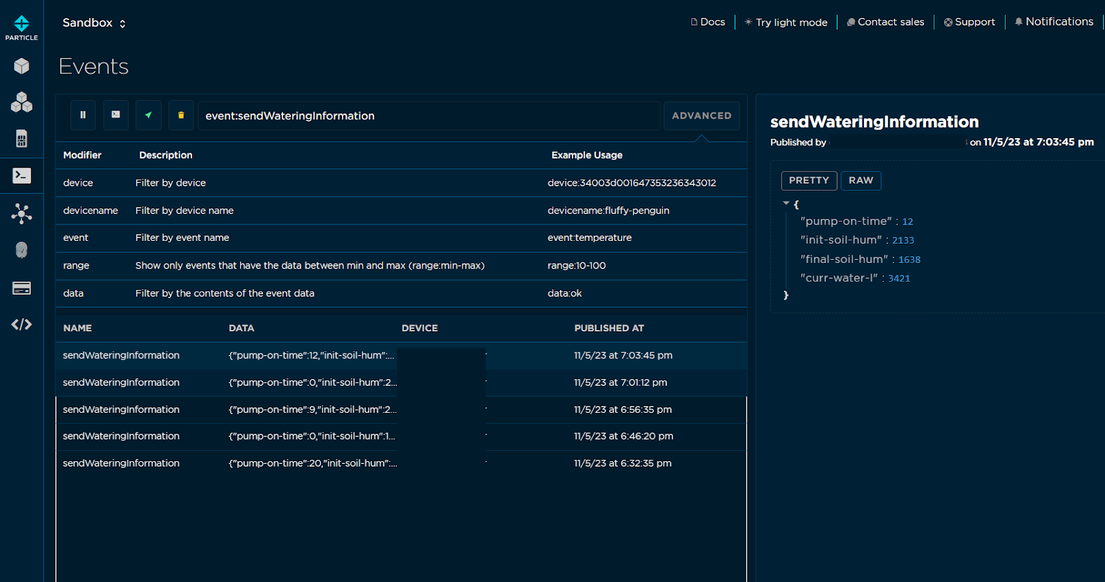
void createEventPayload(int pumpRunTime, int initSM, int finlSM, int waterLvl){//, int envTemp, int envHumd){
JsonWriterStatic<256> jw;
{
JsonWriterAutoObject obj(&jw);
//Pump 1
jw.insertKeyValue("pump-on-time", pumpRunTime);
if(initSM != -1){
jw.insertKeyValue("init-soil-hum", initSM);
jw.insertKeyValue("final-soil-hum", finlSM);
}
jw.insertKeyValue("curr-water-l", waterLvl);
}
// Publish info to DB
Particle.publish("sendWateringInformation", jw.getBuffer());
}
void sop(String str){
if(Serial){
Serial.println(str);
}
if(canSendData){
JsonWriterStatic<256> jw;
{
JsonWriterAutoObject obj(&jw);
jw.insertKeyValue("debug", str);
}
Particle.publish("debugMsg", jw.getBuffer());
}
}
- For debug purposes, you’ll want to publish events to the argon cloud with
Particle.publish(). Although it’d be easier to output numeric values and messages by themselves, I suggest using the ‘JsonParserGeneratorRK’ library to “Jsonify” your data to send as one packet of data, rather than just individual strings of text with data. JsonWriterStatic<256>is the object that will hold our data packet, whileJsonWriterAutoObject obj(&jw)is the object that we will write data to. Since we are able to write more than one type of packet (since we use it both insop()andcreateEventPayload()) we need an object that allows us to flexibly edit the data (autoObject), and also package our data correctly (Static) before we send it.sop()Is what allows us to see debug messages from our Argon. If a serial monitor is available, print to that, and ifcanSendDatais enabled, send debug messages there too.canSendDataAllows data packets to be sent to the particle cloud. This is helpful when you need to usesop(), but not send repetitive messages.createEventPayload()allows us to send watering information to ourselves later. This will be helpful for checking in on our system later.
void safeWater(){
  sop("Safe watering...");
  startTimer();
  startPump();
  int i = 0;
  while(isWaterLevelInThreshold() && counter < MAX_TIME_WATERING){
    if (i < 256){
      i = 0;
    }
    else{
      analogWrite(STATUS_LED, i);
      i++;
    }
    delay(50);
  }
  stopPump();
  stopTimer();
  createEventPayload(counter, -1, -1 , readWaterLevel());
}

void failureLight(int maxTime){
  sop("Doing failure light...");
  startTimer();
  while(counter < maxTime){
    if((counter % 2) == 0){
    }else{
      digitalWrite(STATUS_LED,LOW);
    }
    digitalWrite(STATUS_LED,HIGH);
  }
  stopTimer();
}
safeWater()does the watering cycle based on time, rather than on sensor inputs. I suggest watching your water bucket if this is happening.failureLight()Creates a physical sensor using the onboard LED on the argon to signal a problem with the system. Currently used when the water level is below a specified level.
Once again, the entire code can be found at https://github.com/Disguised-Coffee/project-SaGWS
Connection Stage

There are many ways to do this, but I’ll explain my method here (although I would use different materials!):
- Cut a normal sized water bottle to the size of an 8oz bottle. Use hot glue as needed.
- Shape a piece of scrap plywood down to the rough size of 2x6 inches.
- With the 8 oz bottle, trace the bottom of bottle against the plywood towards the furthest side of the plywood, ensuring that the bottle is fully on it.
- Cut the edges of the plywood by the bottle creating triangular cuts in the plywood from the corners of the bottle.
- Create adjacent slits in the wood in place of the triangular cuts in the plywood.
- Using yarn, tie the 8 oz bottle to the plywood.
- With a hot glue gun, glue the knots made with yarn.
My water level looked like this (there is a cap for the bottle!):
- With the potentiometer and the lever, mark an ideal place on the lid of the ice cream bucket in which the water level arm can freely go through and also does not touch the edges of the bucket. Once you find these ideal positions, mark them with a Sharpe.
- Hot glue the end of the potentiometer to the lever plate.
- Cut a slit in the lid of the water bucket. If your measurements do not work, do step 8 again. You can also utilize layers of cardboard as a platform for the potentiometer.
- After the water level has been secured to the lid, create holes in the lid for the pump wires and tubing. (Make sure you put your tube on your pump beforehand!)


My final product:

Create Casing for Argon and Relay

I formed a box with table-like legs to prevent my argon from getting wet in case the water leaks onto the table where I set up my project.
- Using a piece of cardboard, trace a rectangular perimeter of the lid, not outlining the lid.
- Trace two similar rectangles north and south of the lid and two similar rectangles on the west and east sides of the lid, ensuring that the height of each rectangle is similar.
- Using a box knife, cut the outer perimeter outline of the box trace, removing the extra cardboard.
- Then using the box knife, press into the interior outline (lines touching the lid) of the box, ensuring not to cut fully through the cardboard.
- Fold the box together inwards from the cuts.
- Hot Glue the box together, using tape to hold the box together if needed.
- Then using the spare cardboard, create 4 1 x 3 inch squares, tracing a line in the middle.
- Using a box knife, carefully cut into the line, not cutting through the box.
- Fold the legs together from the cut, forming an L shape. You can retain the shape by using a piece of tape.
- Hot Glue the legs to the box’s corners.
- Place the argon and relay into the box, sorting your wires as well.
- Use two pieces of tape to keep the lid on top of the box.
Test Bucket Water Tank Components
- After attaching the tubing to the pump, place the pump in the bucket. If the connection point from the pump to your wire is within the bucket, I highly recommend soldering your wires from the pump, as the pump’s wires are short.
- Route the pump tubing and the power wires through the lid of the bucket.
- Before you put any water, DOUBLE CHECK YOUR WIRING AND PUMP SEAL. The last thing you want is an electrical short in the system!
- Once ensuring the wiring of everything, add water into the water tank, making sure not to overfill.
- Put the end of your tube into the bucket, so that the water flows back into the bucket once the relay turns on.
- Flash relay testing code onto the argon to ensure that the pump does run. If not, ensure your wiring is correct and run the relay testing code. If not, refer to the next step.
Calibrate Soil Sensor and Potentiometer Global Variables

- We didn’t calibrate this first, since these are analog sensors and voltage drawn by other components affect the value returned by these sensors.
- If you don’t have a serial monitor, another way you can calibrate the system is by using the debug messages located in the Particle console under ‘events’
- From the IDE, go to ‘Console’ (bar chart icon) and click on ‘Events’ (terminal prompt icon)
- Adjust global variables such as
DRY_SOILorWET_SOILor evenMIN_LVLto adjust when the system should water your plant. Use your serial monitor to tune these constants! - You can find
WET_SOILandDRY_SOILby putting the soil sensor in the pot of a watered plant and printing out the value of the soil sensor while runningwaterTheFlowers(), keeping the end of the tube towards the funnel of the bucket.
[Optional] Setup Plant
I wanted to grow a plant with my setup instead of watering an already growing plant. If this is you, do the following:
- Grab some soil from a bag of soil, outside, or from a dead plant (if from a dead plant, remove the main root of that plant) and place in a pot. Ensure that the soil is broken up and not in chunks in the pot.
- Using your index finger, make a 2-3 inch deep by .75 inch wide hole in the soil.
- Place seeds of your choice into the pot. I used some Marigold seeds I happened to have around.
- Cover the seeds up with the surrounding soil in the pot.
Place Soil Sensor and Watering Stake

- Place the wooden stake (or floor shim) within the pot. Refrain from taping the tube to the stake for now.
- Place the soil sensor about 2 inches away from the stake and press down on it carefully until the sensor’s white line is about ½ an inch above the soil.

Test the System!
Once your values are calibrated, ensure that the watering system is able to run the water cycle when there is dry soil!
Periodically Check-in on the System

I suggest every 5 days at the least, depending on your plant, to ensure that your watering system is functioning smoothly.
Some problems don’t arise right away, such as molding pieces of wood and faulty, leaky Frankensteined ballasts (don’t ask me how I know that…)
Expand
In the case that everything does work, there are multiple paths to take:
- I highly recommend adding a separate power supply (such as 3 1.5V batteries to supply one section of the breadboard for the pumps to prevent electrical shorts with the argon, as mentioned earlier.
- Originally, I planned to graph the values from my sensors, including adding a DHT-11 Adafruit Sensor or an analog temperature sensor to document watering time of my plants based on environmental variables, using a database. I attempted the QuestDB integration (which is in the Particle Docs) but I intend to use MongoDB with API calls later on.
- I also wanted to explore making a Web App server with NodeJS and ExpressJS to fetch data from the database server and current state of my garden, as well as trigger watering events with webhook API calls.
- Another expansion route would be using a different sensor and an altered setup to account for self-watering pots, since my indoor garden setup utilizes more of these types of pots. (Something such as a water-level sensor and a 12 gallon bucket should work).