Self Watering Plant System
by KatharinavanEck in Circuits > Arduino
575 Views, 0 Favorites, 0 Comments
Self Watering Plant System

For most people its hard to keep track of watering their plants. For this project I want to research and create a solution for this problem. The hypothesis question is as follows; “Can I create a self watering plant system that can give digital feedback?"
The sketch shown is an idea of how the end project could look like.
The idea is that I will connect the ESP8266 to a soil moisture sensor which is put in the soil of a plant. The sensor will read the moisture in the soil of the plant and give a positive or negative feedback to the ESP8266. When the feedback is negative (which means there is not enough water in the soil) the servo motor will turn. The servo motor will be connected to a wire or straw, which will be connected to a watertank/bottle. This way the plant can get water.
Supplies
- ESP8266 with grove extentsion
- Servo motor
- Soil moisture sensor
- Powerbank
- Water bottle
- Straw
- Tie Rip
- Piece of wood
- Lasercutter
- Phone
- Telegram app
Moisture Sensor
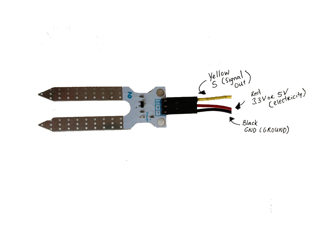
I will start step by step with coding the ESP8266. You will need Arduino installed on your computer with the ESP8266 libraries.
The first step is the moisture sensor.
We will start with connecting the soil moisture sensor to A0. You do this by plugging the grove pins into A0 and connecting the wires with the soil moisture sensor. On the image you can see how to connect these wires to the sensor.
Next up connect your ESP8266 to your computer and start the Arduino software to start coding. Before entering any code, check the settings at 'Tools'. Set the Board to 'NodeMCU 0.9", Upload speed to "115200" and make sure the Port is your USB port.
Upload the following code to your ESP8226;
<p>#define SensorPin A0 // Here you define where the pin is connected<br>float sensorValue = 0;
void setup() {
 Serial.begin(115200);
}
void loop() {
 for (int i = 0; i <= 100; i++)
 {
   sensorValue = sensorValue + analogRead(SensorPin);
   delay(1);
 }
 sensorValue = sensorValue/100.0;
 Serial.println(sensorValue); </p><p> delay(30); </p><p>}</p>
If you did it correctly you will see the data back in the serial monitor.
Servo Motor
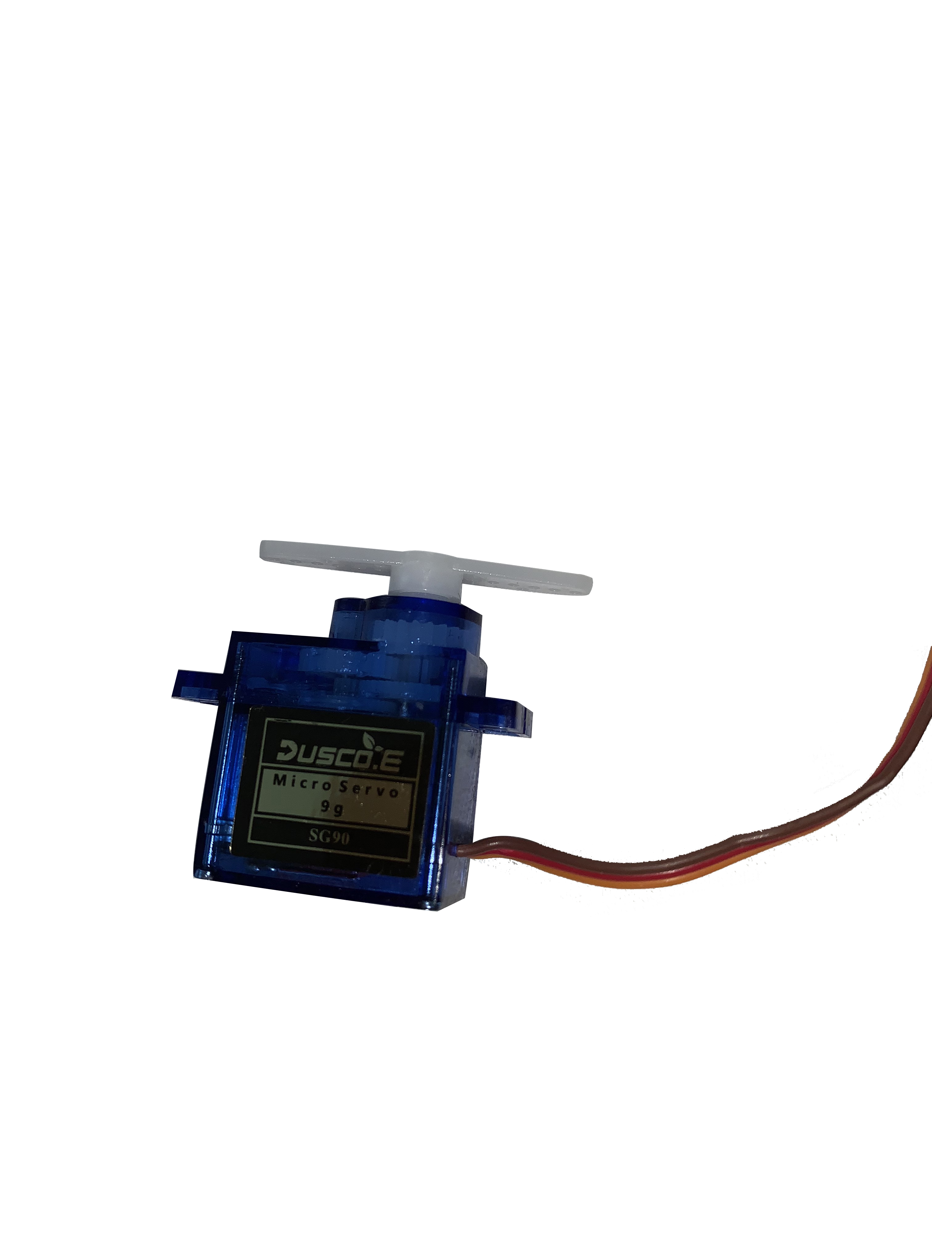
With the moisture sensor working and being able to read the soil, I want the servo motor to react to this. I will be writing an if else statement. If the soil is wet enough the servo motor doesn't move and when it needs water it does move.
Before you add this code you will have to download the servo library. Then attach the servo motor to D8. In the comments of the code I explained exactly what the code exactly does.
#include //this is the library for the servo motor
Servo myservo; //define the servomotor int pos = 0; //the position of de servo motor starts at 0#define SensorPin A0 // the moisture sensor is connected to A0 float sensorValue = 0; //The sensor starts with a value of 0 void setup() { Serial.begin(115200); myservo.attach(D8); //the servo motor is attached to d8 } void loop() { for (int i = 0; i <= 100; i++) { sensorValue = sensorValue + analogRead(SensorPin); } sensorValue = sensorValue/100.0; Serial.println(sensorValue);
if(sensorValue<40) { //if the sensor value is below 40% Serial.println("too low on water"); for (pos = 0; pos <= 180; pos += 1) { //this is a for loop where the degrees of the servo are declared myservo.write(pos); delay(30); //this delay is how long it takes to the position
} }
else { Serial.println("the water is okay");
} delay(1000*60*10); //here you decide how long the intervals are between the checkups on the water, i chose for 30 minutes }
With this code the moisture sensor will check the plant every 30 minutes. When the moisture in the soil is less dan 40%, the servo motor will move 180 degrees.
The Planter
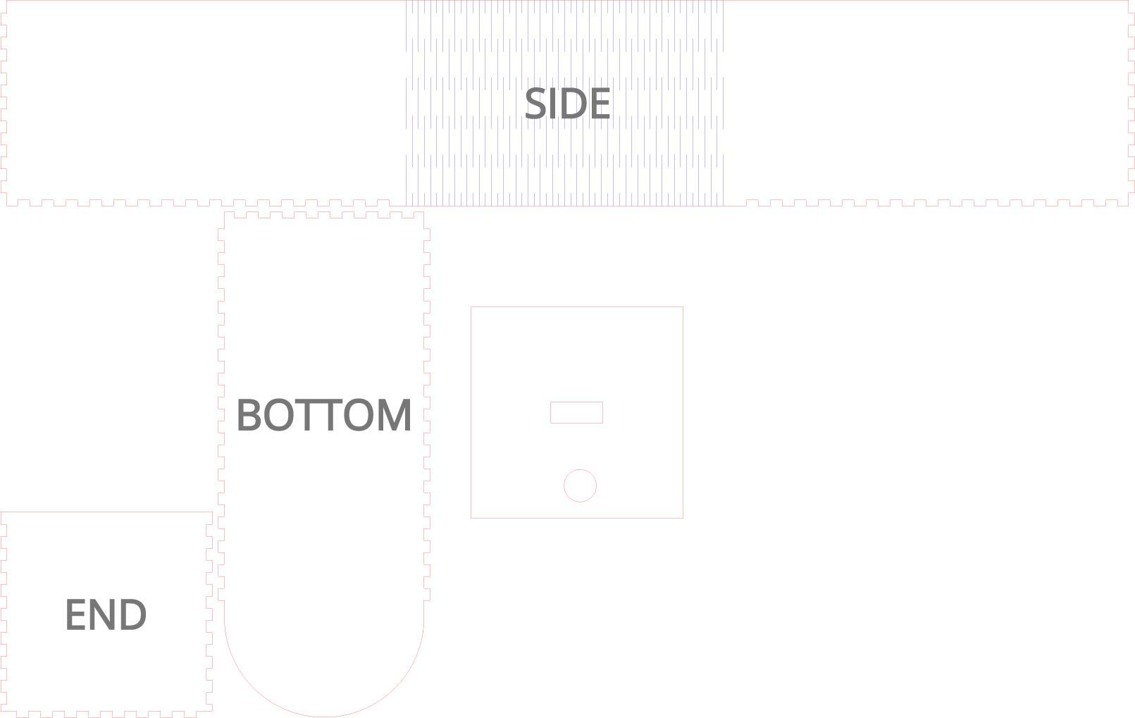
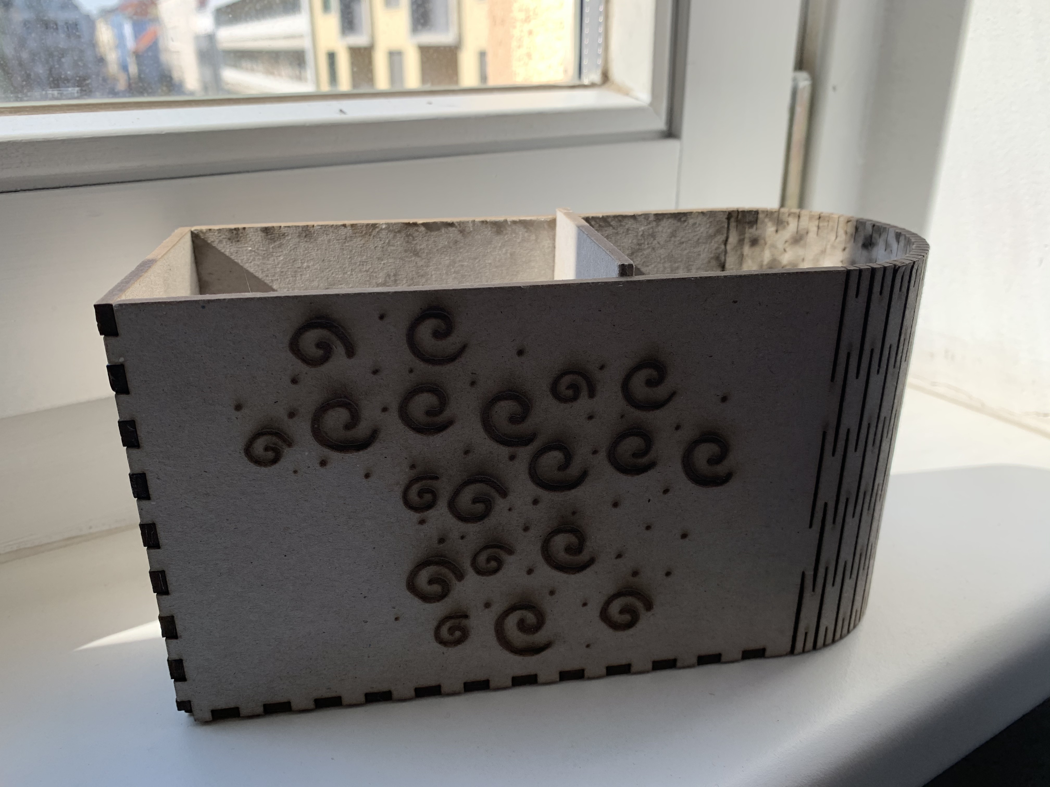
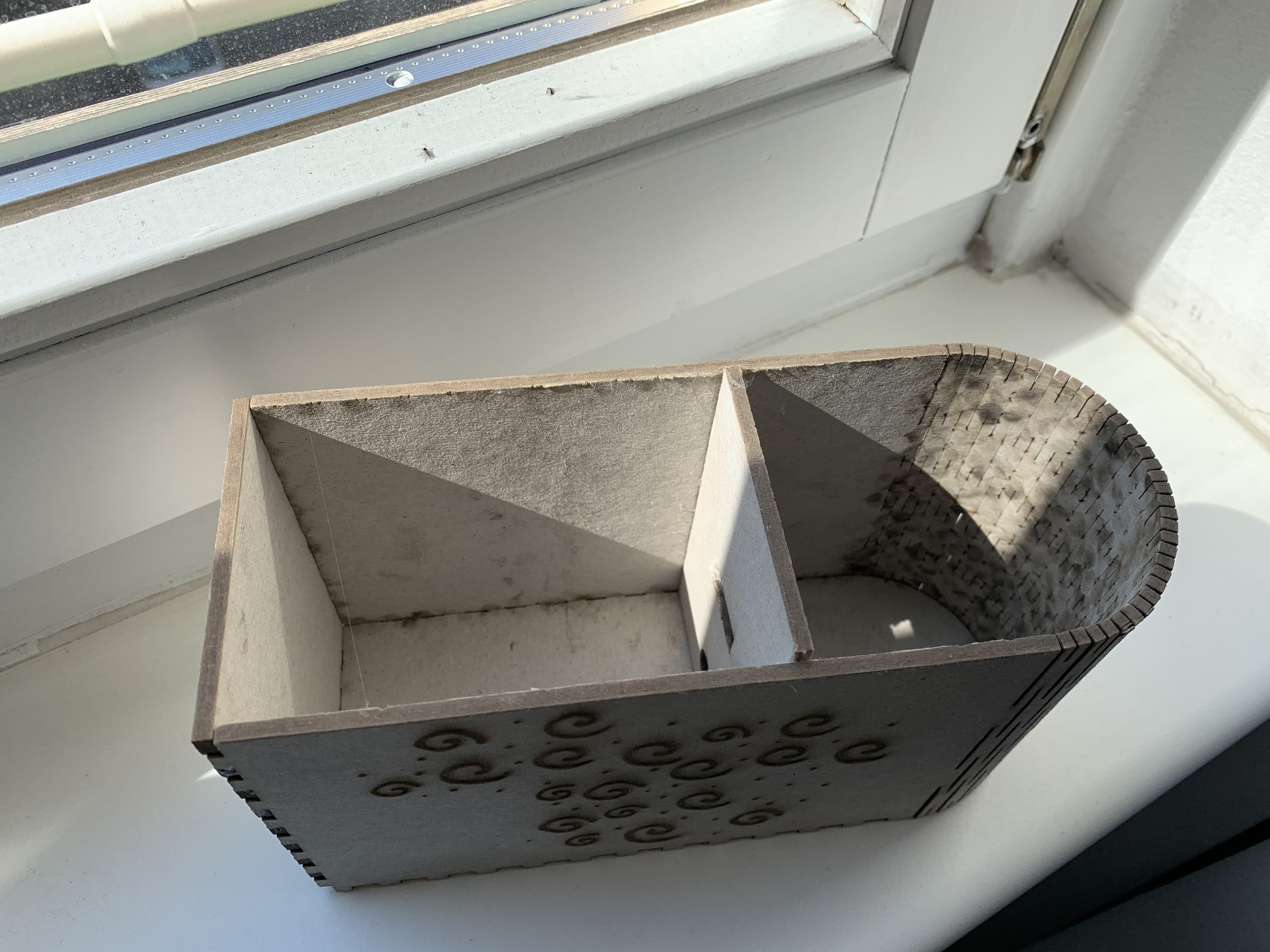
To contain the self watering system we will make our own planter. For this I used the website https://www.makercase.com/#/kerfbox to make a simple vector sketch to lasercut. I made the open kerfbox with the measurements of 200mm x50mm x 100mm.
The vector sketch then was lasercut out of 3mm wood. For this I used standard lasercut settings for 3mm. To add some decoration I engraved decorations on the side of the planter. With the cuts in the middle of the long part, it will be able to bend. Assemble the pieces together.
For the divider/the middle piece of the planter I used the same size as the END piece. Here I created two holes, one for the soil moisture sensor and the other for the water supply. This one doesn’t fit like a puzzle on the planter so I glued this part. On one side of the planter you can add your soil and plant. On the other side we will put the ESP8266 and the components.
The Water Supply
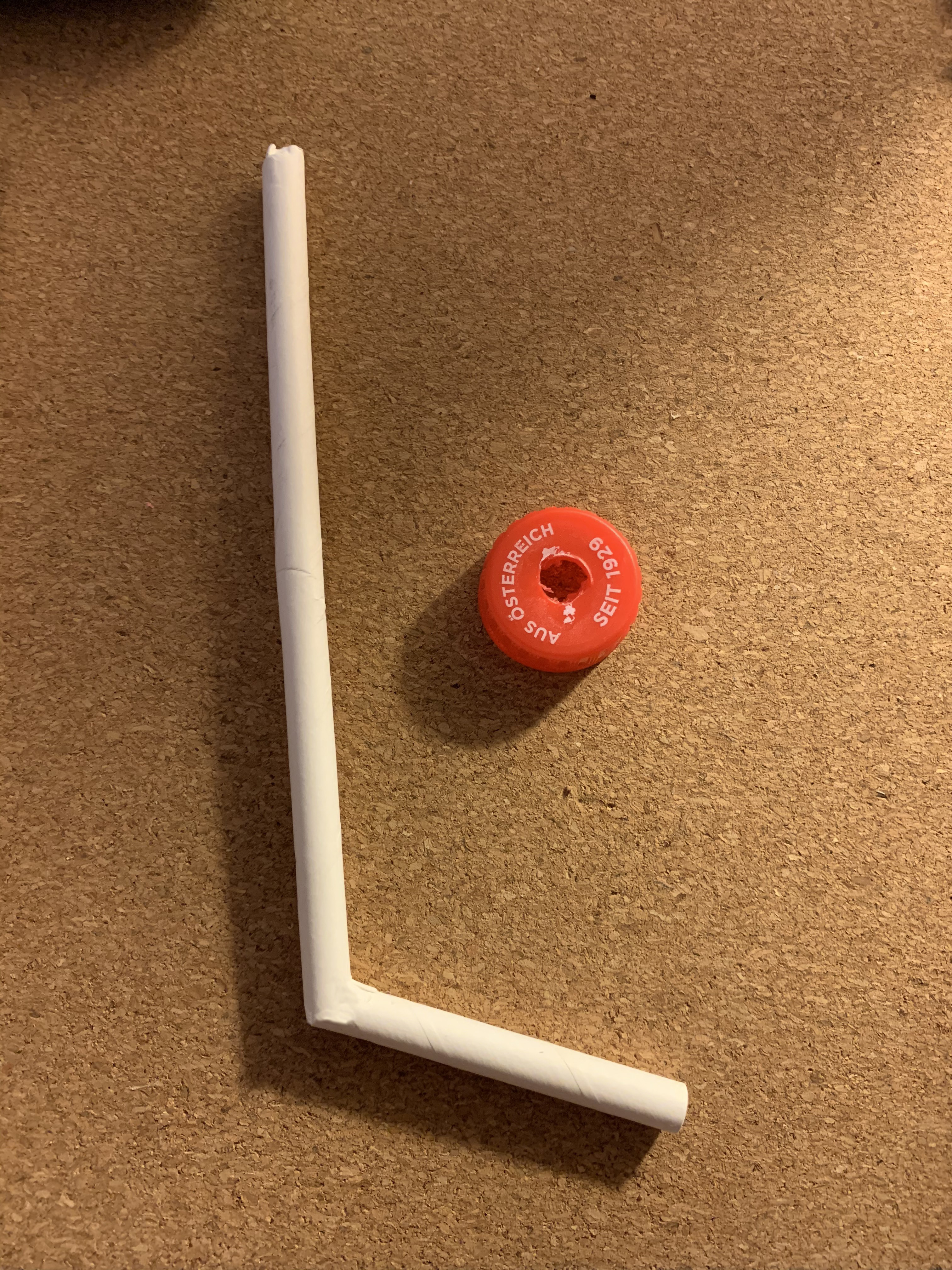
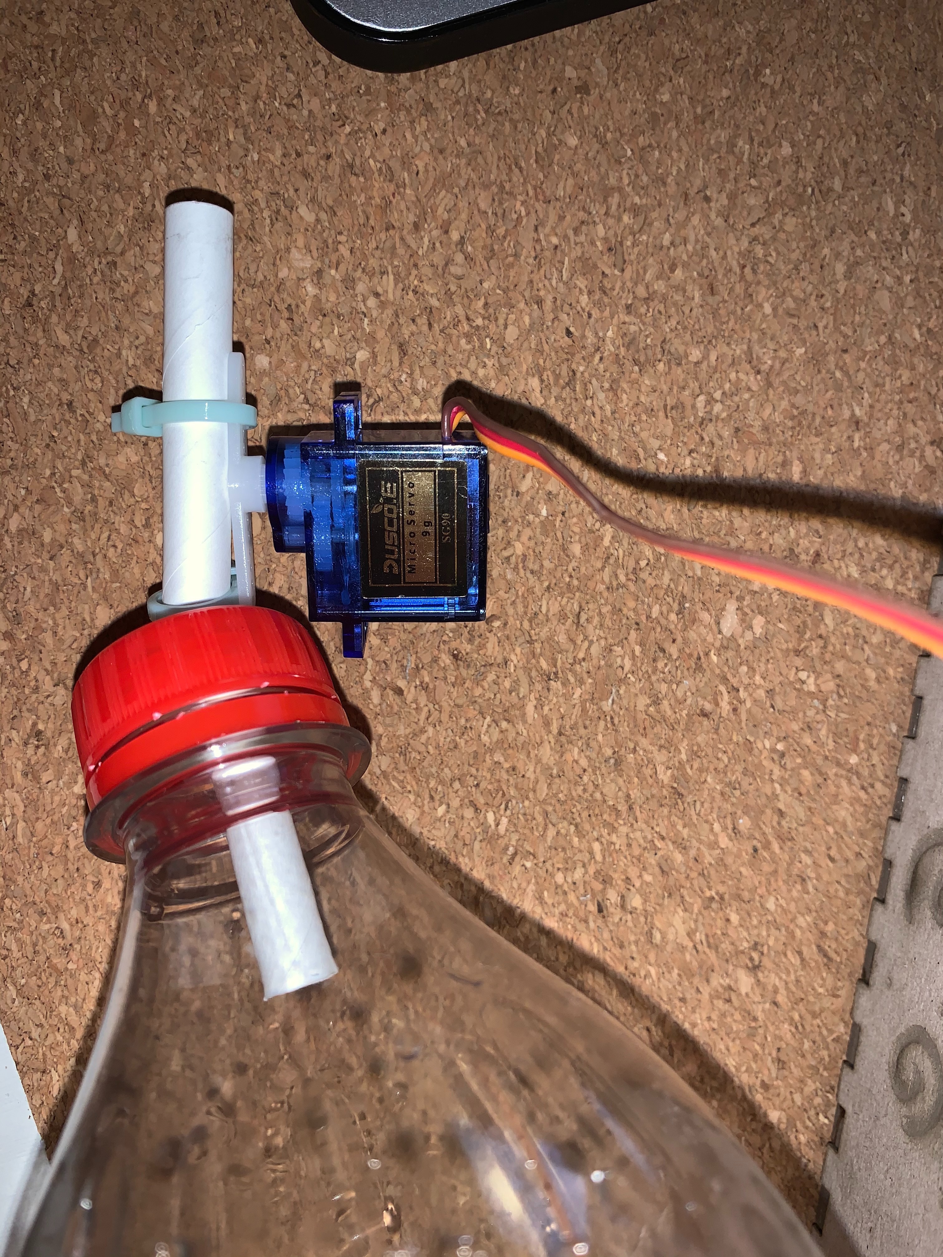
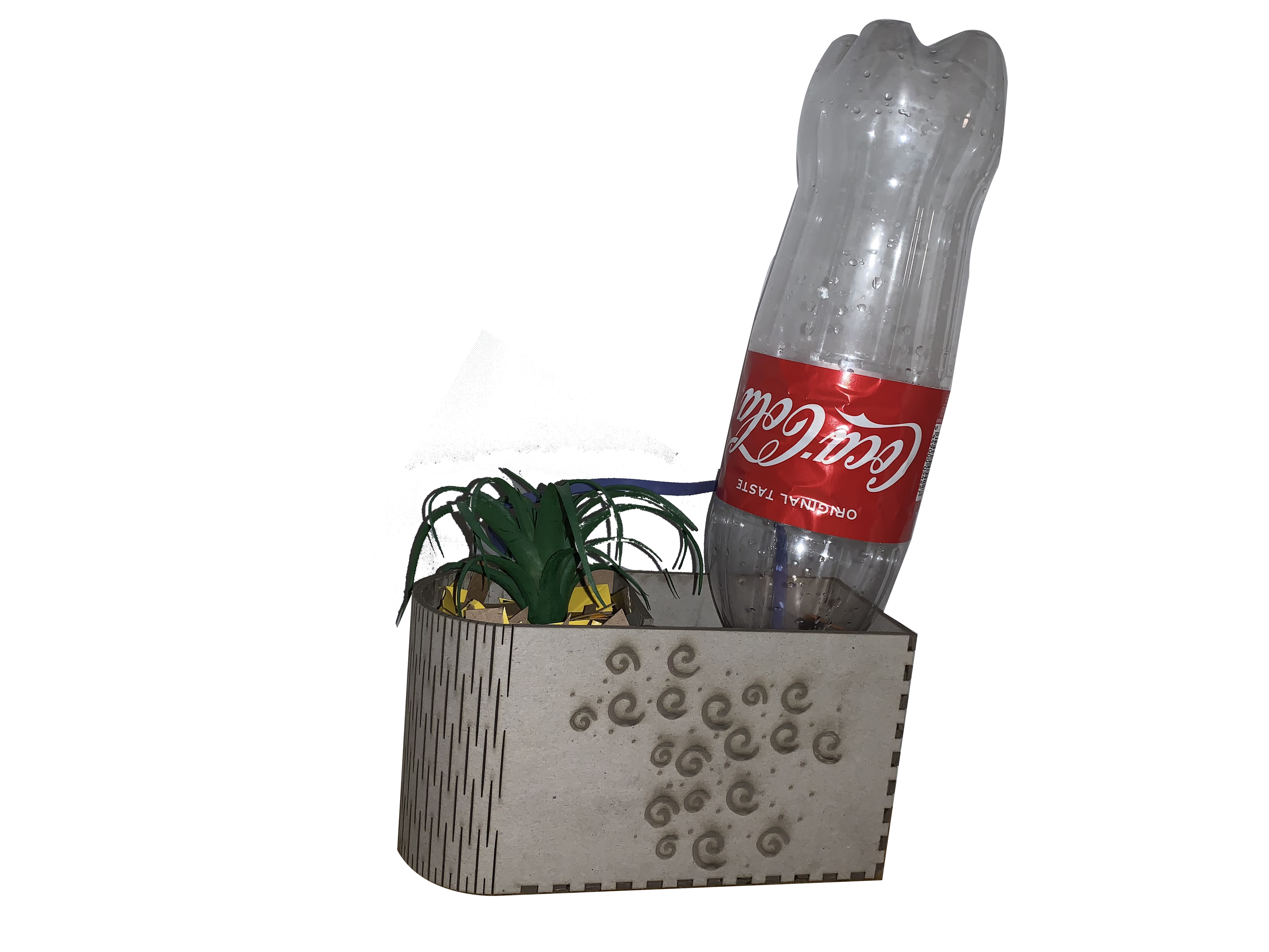
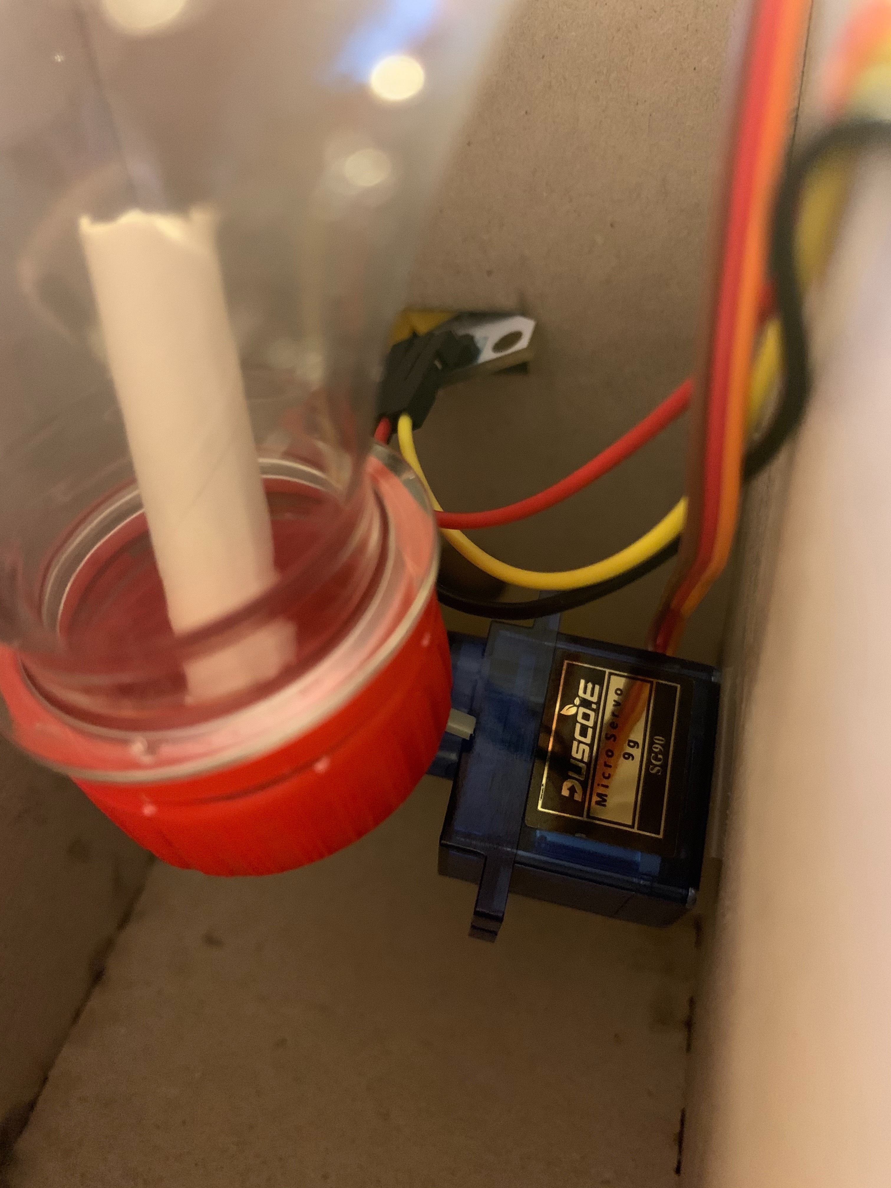
For the water supply we will be using a bottle or carton with a cap, and a straw. Make a hole in the bottle-cap and (hot)glue the long part of the straw into the bottle. Use tie rips to attach the servo motor to the other end of the straw. Make sure the servo motor is now at pos(0); (Starting position, the straw should be unable to flow water into the planter). Hotglue the servo motor to the side of the inside of the planter, which will make your bottle stand upwards into the planter.
Attach the moisture sensor and pull through the hole, see pictures of the inside of the planter.
Now when the code is running the water will flow into the soil if needed.
Digital Feedback - IFTTT
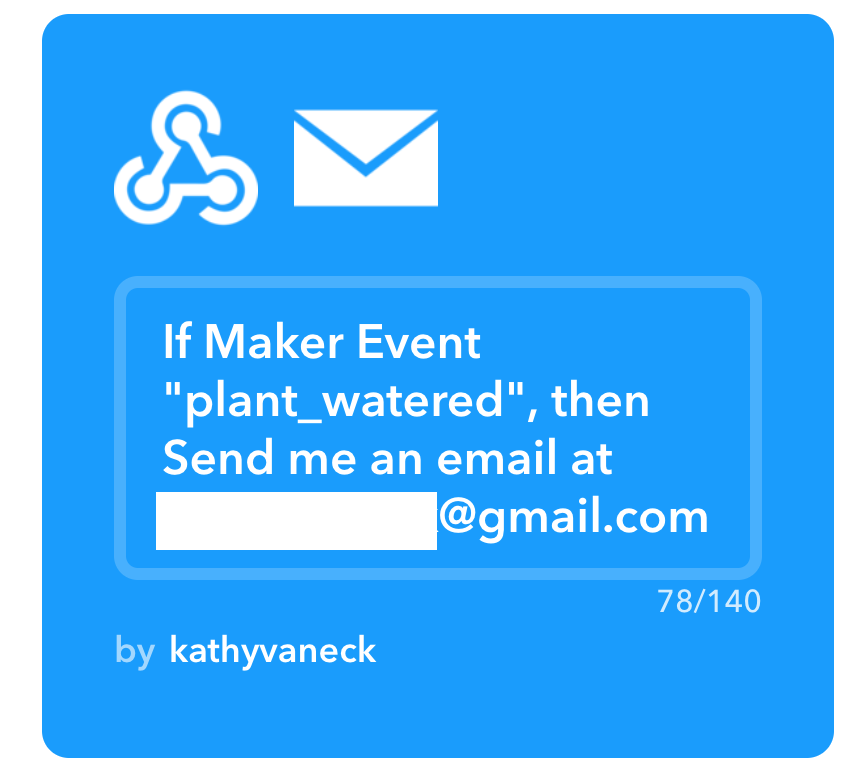
For the last part of this project I want to get digital feedback of the planter. After some research I found out this is possible to do using the IFTTT service; https://ifttt.com/applets
Make an account on IFTTT. Login and go to the service and create a new applet. Click on the IF and select the application "webhooks". Name the event 'plant_watered". Then click on the 'Then' and choose email. Now this 'recipe' of IFTTT will send you an email if triggered.
The next step is to include the IFTTT trigger in your ESP8266 Arduino code.
In the IFTTT service go to webhooks, the service you just connected to your own applet. Click on settings, here you will be able to view your own URL, which we will need for the Arduino code. (https://ifttt.com/maker_webhooks/settings)
After this it got tricky for me - So for now I will leave it here.
You've got yourself a working self watering plant - if you would like to discover how to make the digital feedback, I suggest to try and follow the following tutorials