Self Calibrating Sundial
by poblocki1982 in Circuits > Arduino
18067 Views, 137 Favorites, 0 Comments
Self Calibrating Sundial
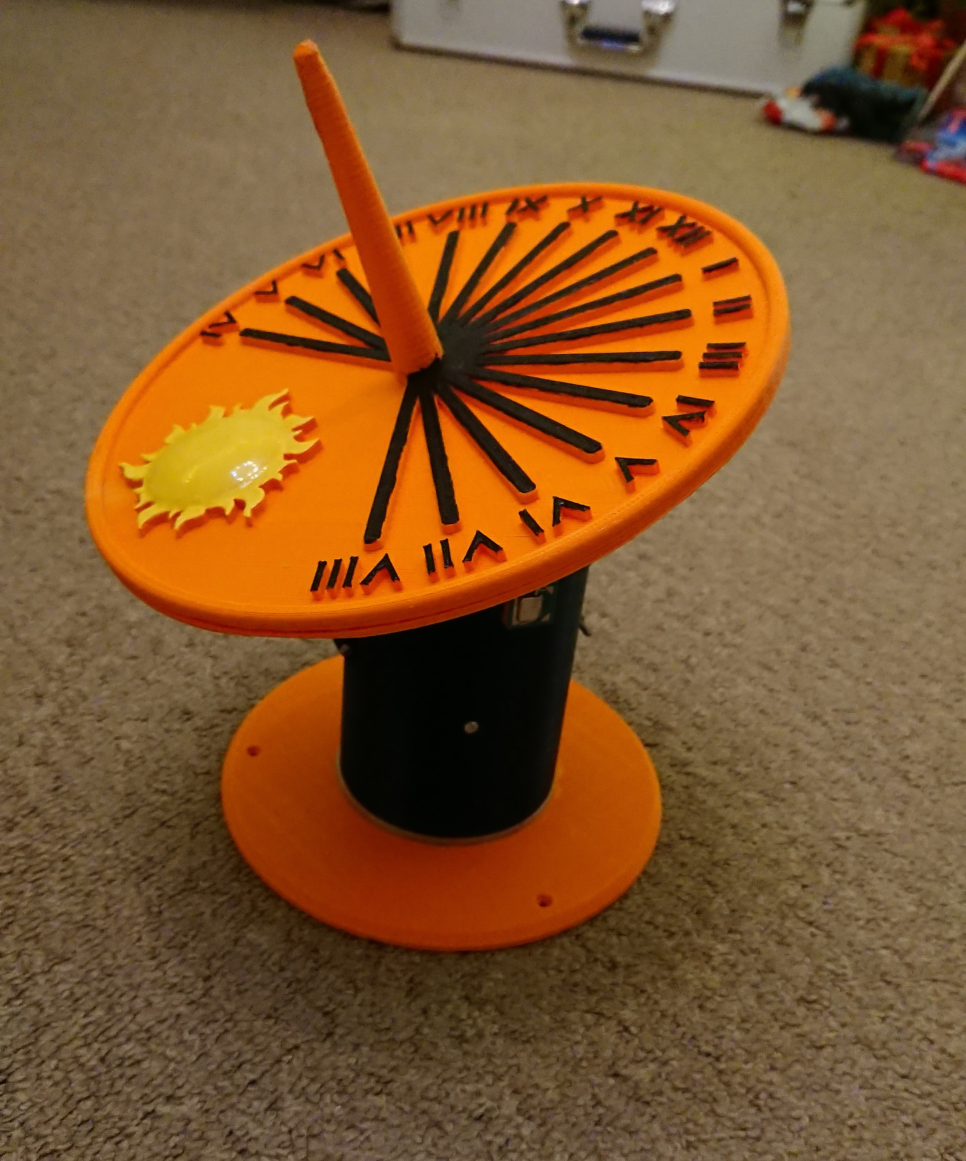
I am an amateur astronomer and I have a small obsession regarding sundials. There are few types of Sundials, but all of them require calibration like positioning in South-North direction and tilting the plate at your latitude angle. I wanted to create Sundial that could be placed anywhere and it would calibrate itself.
Firstly I had to choose the right type of Sundial. Horizontal Sundial are easy to make, but the gnomon has to be mounted at the angle of your latitude, so if you change location you have to adjust the angle of the gnomon and the positions of the hour marks on the plate. In equatorial Sundials the gnomon is perpendicular to the plate and then the entire plate is tilted at latitude angle plus the hour marks are evenly spread every 15 degrees. I chose the equatorial Sundial because you don't have to adjust the hour marks and it's easy to tilt the entire plate at latitude angle.
I also had to come up with the system for the Sundial to find North-South direction so I used digital compass HMC5883L and continuous rotation servo. To find latitude I used Neo 6M GPS module.
Supplies
- Arduino Nano
- 2 x SG90 Servos
- 9V battery
- 9V battery clip
- 2 x M3x20mm bolt with nut
- Superglue
- Solder iron
- PLA/ABS
Tools:
- Soldering iron
- 3D printer
- Philips screwdriver
Software:
- Arduino IDE (https://www.arduino.cc/en/main/software)
- Cura (https://ultimaker.com/software/ultimaker-cura)
CAD and 3D Printing
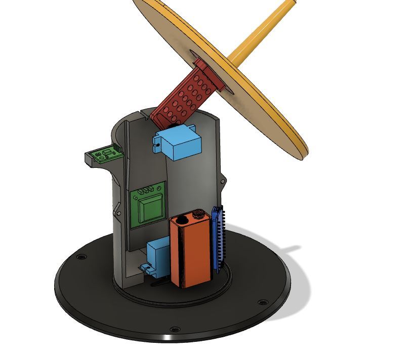
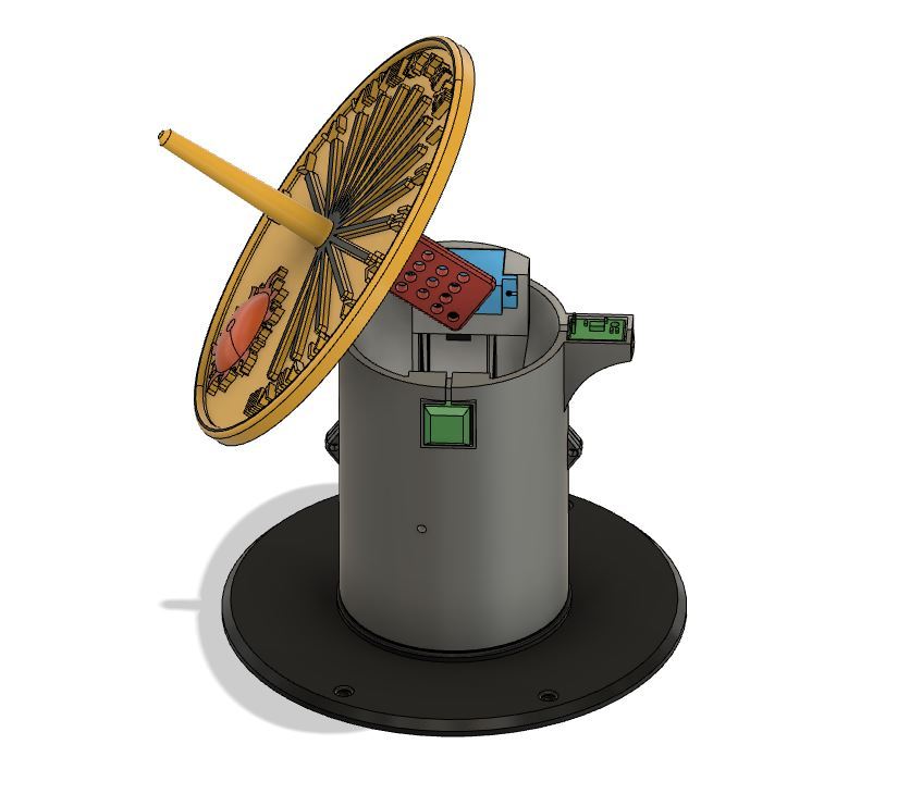
It took me about 20 working hours to design Self-calibrating Sundial and I had to make few adjustments after printing prototype. There is slot for GPS module and the antenna and the module itself is mounted inside the main body, but the antenna have to be mounted outside to maximise signal.
The digital compass is installed at the top of the main body to keep it as far as possible from interference from other electronic parts. I designed the slot for it, exactly on the South-North axis so it can be mounted only in the correct position.
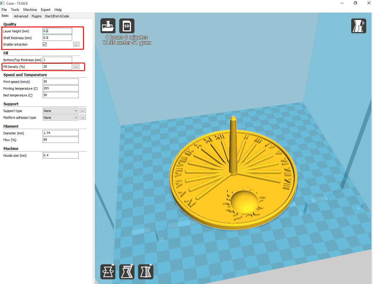
I would recommend to use Cura for slicing model, but if you have your favourite slicing software that works well, there is no reason not to use it. I printed model in PLA, no brim or raft and 20% infill which is more than enough. I usually print with standard layer resolution 0.2mm, but if you wish to speed up printing you can increase the resolution to 0.3mm which is about the maximum for most FDM printers (without any upgrades).
NOTE: You have two different versions of the sundial plate, large and small. On the pictures above you can see the large version, but it you have smaller size 3D printer you can mount the smaller plate instead.
Uploading the Code
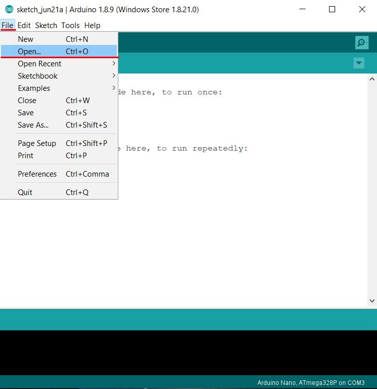
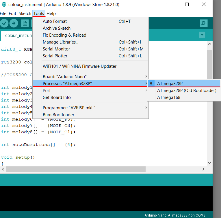
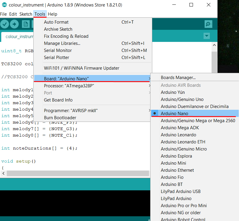
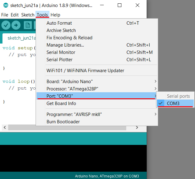
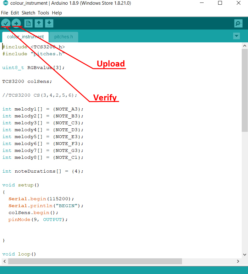
Here is the code that you have to upload using Arduino IDE and instructions how to do that.
- Open Arduino IDE
- Open the code [File -> Open -> colour_instrument.ino]
- Connect Adruino Nano to PC/Laptop using USB cable
- Choose COM port [Tools -> Port “…” -> COM…]
- Choose Arduino board type [Tools -> Board: “…” -> Arduino Nano]
- Choose Arduino Nano processor type [Tools -> Processor: “…” -> ATmega328P] [It is possible that you will need to change it to ATmega328P (Old Bootloader) depending on Arduino Nano]
- Verify the code
- Upload
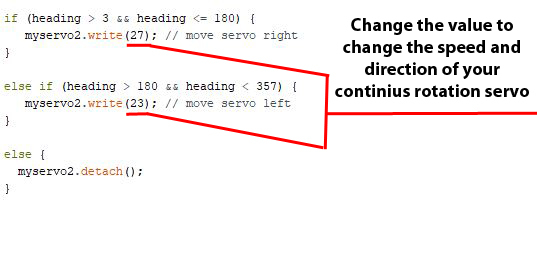
NOTE: After uploading the code and putting all electronics together, you will have to calibrate your continuous rotation servo. Change the value of myservo2.write(xx) ; (see picture above) to change speed and direction that your servo moves.
At certain value servo will not move and then if you increase that value it will move slowly left and if you decrease that value it will move slowly right. By increasing/decreasing that value more you can increase the speed.
I recommend to keep it slow as that will give Arduino the time to read the digital compass value and stop when it finds South.
I'm also still learning Arduino programming so the code is not perfect, but it works for now :)
Downloads
Making Continuous Rotation Servo
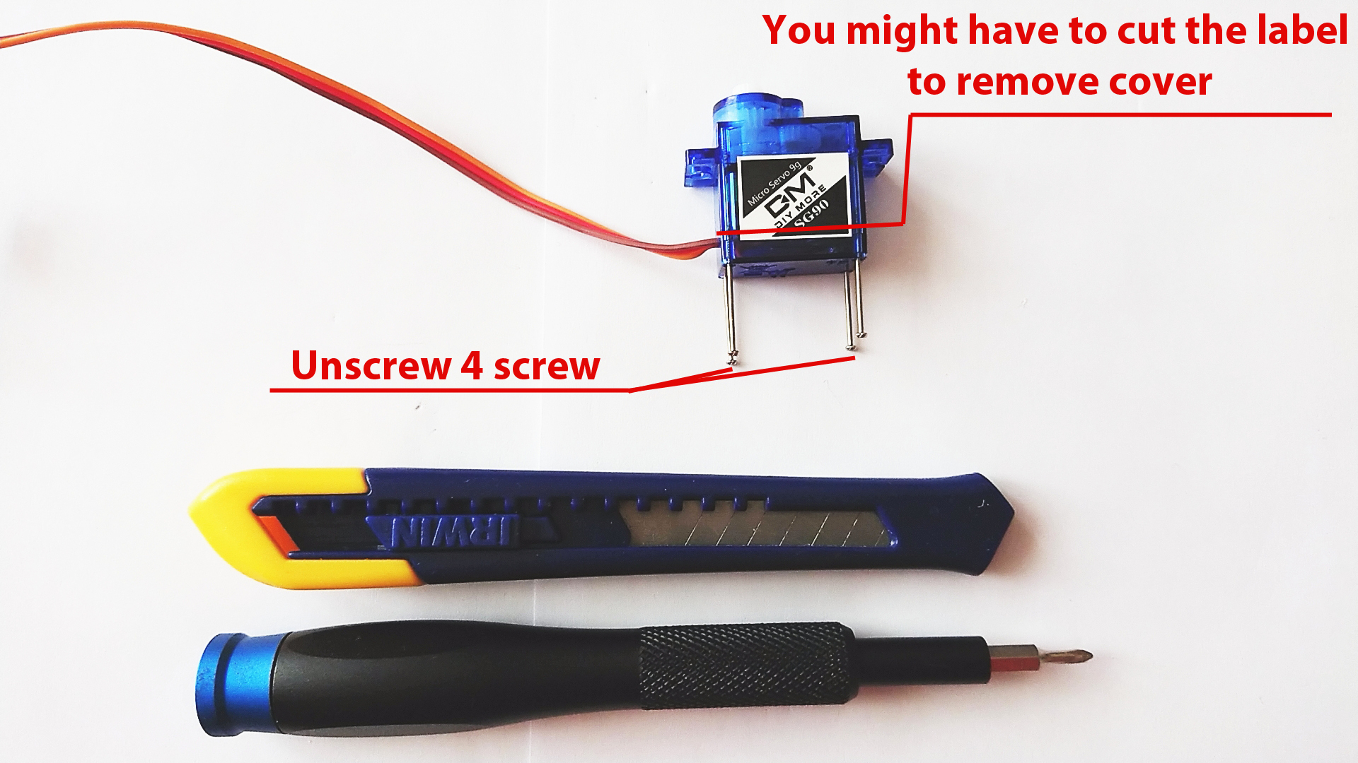
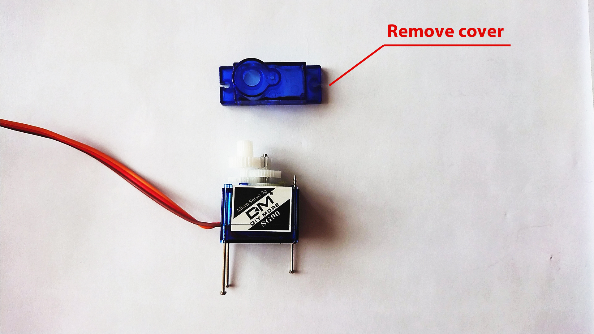
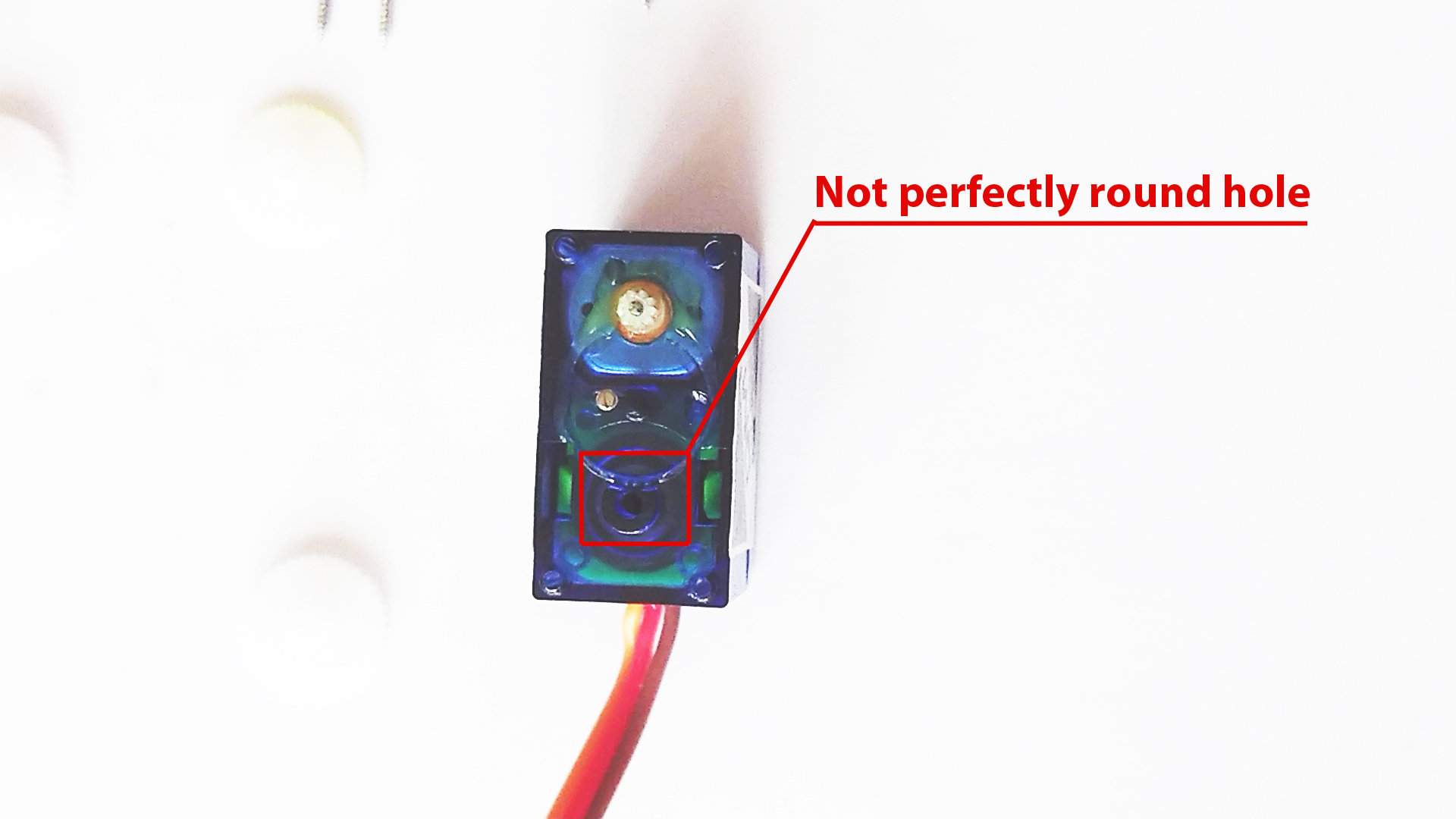
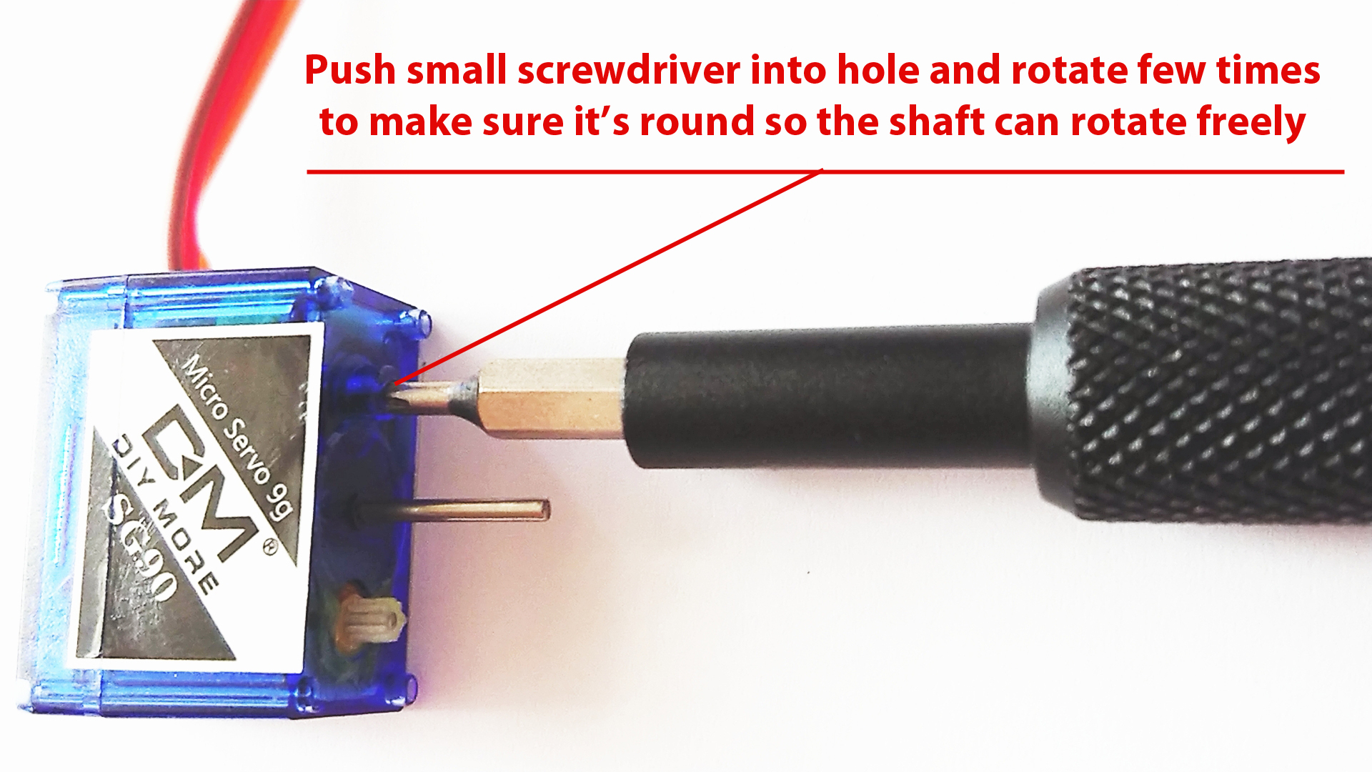
Standard SG90 servo is limited to 180 degrees movement and you have two options: either buy 360 continues rotation servo (expensive) or hack 180 degree servo and convert it to continuous rotation (cheap). Here is how to do it:
- Use Philips screwdriver and unscrew 4 small screws at the bottom of the servo and then remove the plastic cover.
- Make sure to put all the cog wheels back in the same configuration like on the picture above.
- Make a hole with small screwdriver where the shaft (see picture) supposed to go.
- Put all the cog wheels back in place and then screw the servo cover
You might come across different version of the SG90 servo and to change it to continuous rotation servo might need to follow instructions on this YouTube video https://www.youtube.com/watch?v=zV_5wUo7Kxs&t=104...
Electronics
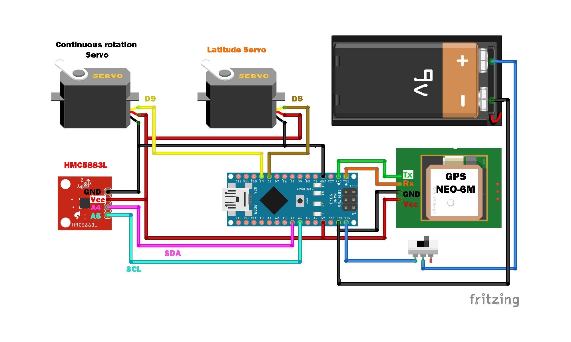
Please follow the connection diagram (see picture above) and then mount all components inside the cylindrical main body.
NOTE: If you decide to upload the code after soldering all components, make sure you disconnect Rx/Tx from GPS module as the code won't load.
Assembly
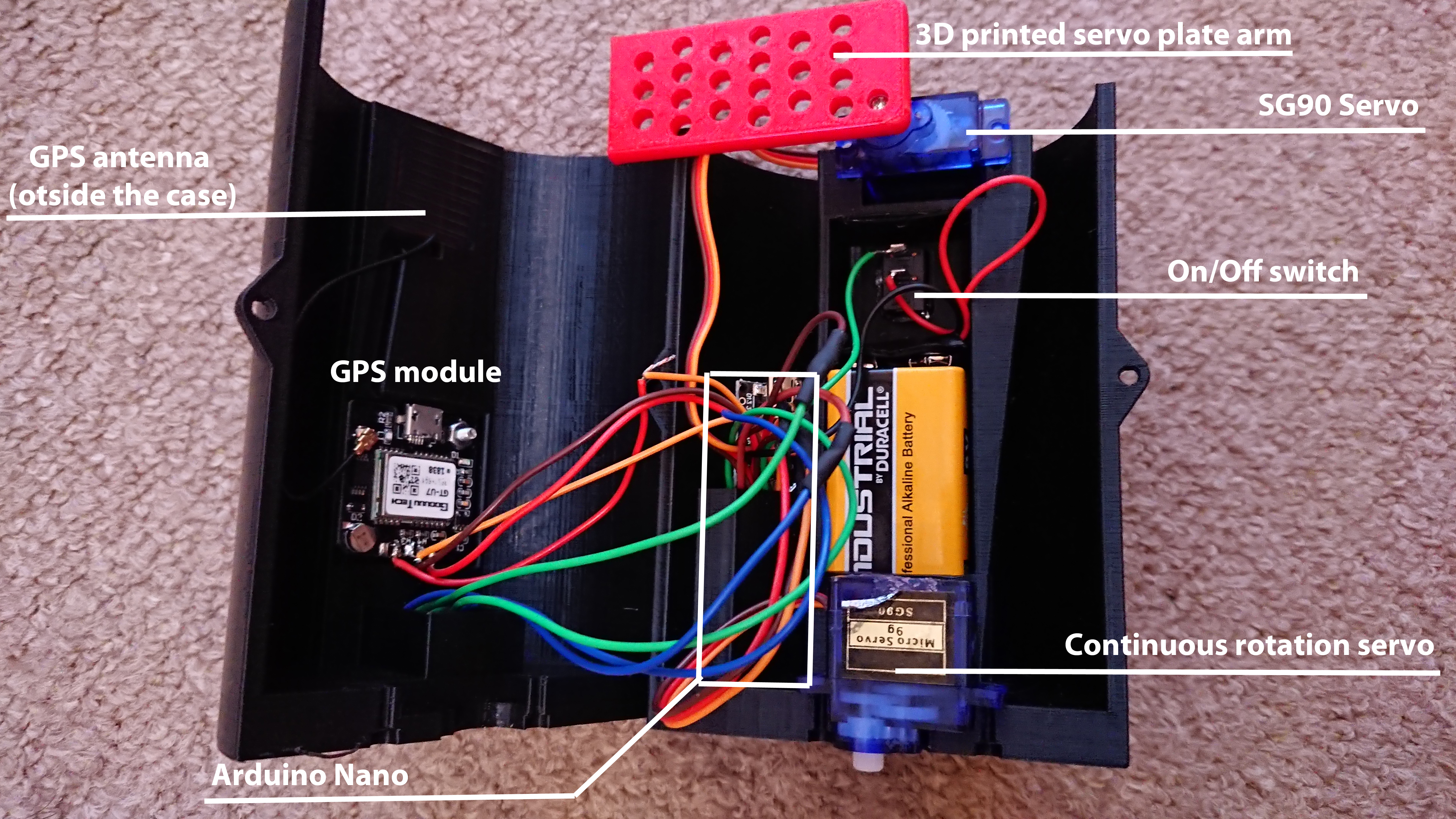
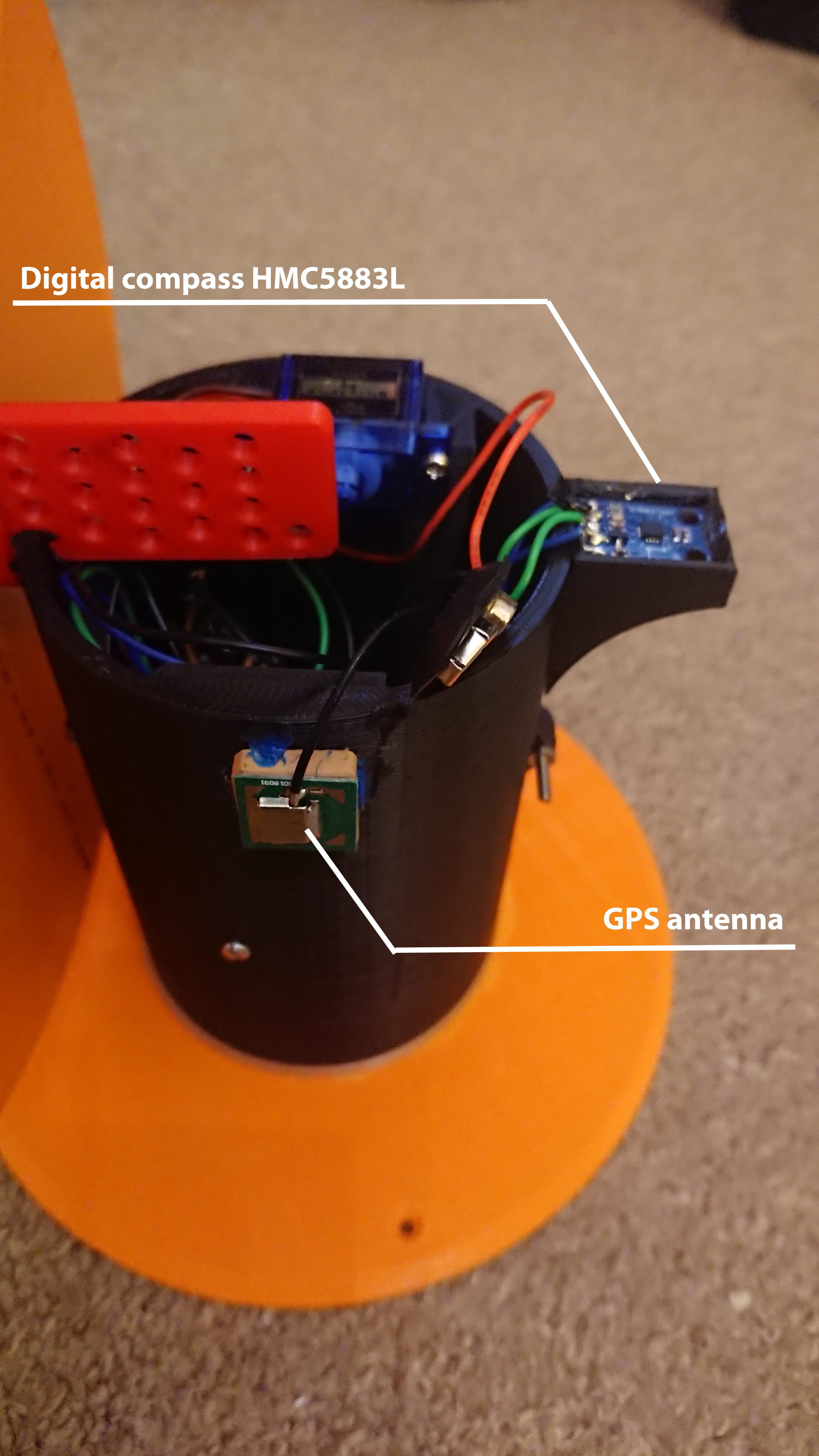
- Glue the servo arms (should be included with SG90 servo) into bottom plate and into sundial servo arm
- The continuous rotation servo (the one we hacked in previous step) goes at the bottom and will be responsible for rotating entire Sundial and finding South-North direction.
- The regular SG90 servo should be mounted on to of the cylindrical case and then you can attach the 3D printed servo arm with glued arm.
- Mount GPS module with the antenna (remember to mount the module itself inside the case and the antenna outside)
- Mount on/off switch in the case
- Mount the digital compass in the slot at the top of the cylindrical case (see above picture)
- Put Arduino Nano and 9V battery in the designated slots (see above picture)
- Put two halves of the case together and use M3 bolts on both sides to secure it
- Glue the Sundial plate to the 3D printed servo arm (red part on the picture above)
Self-calibrating Sundial in Action
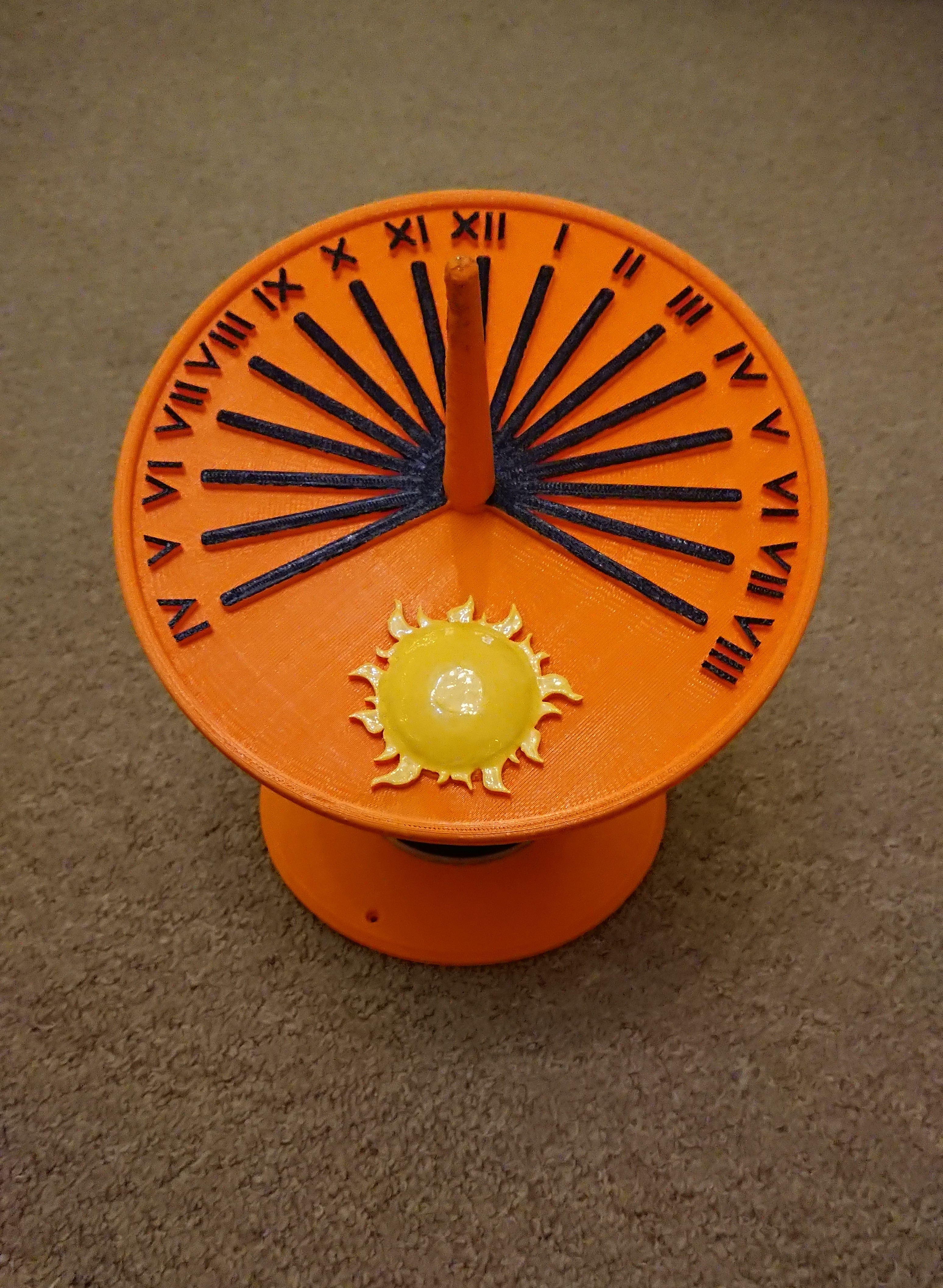
The video below shows finished, working self-calibrating Sundial. First video is showing simulation in Fusion 360 and the second video is the actual Sundial. As you can see, after switching it on, it will rotate clockwise/anti clockwise until it finds South. Once that is done, you have to wait for GPS to find signal. Then it will transmit the latitude to the servo and it will tilt the plate at latitude angle.
This way this Sundial can be positioned in any direction and at any latitude. The only thing to remember is that it has to be placed on even ground.