Seeed Studio CAN-BUS V2.0 Hacking - Getting Started
by mviljoen2 in Circuits > Arduino
13577 Views, 27 Favorites, 0 Comments
Seeed Studio CAN-BUS V2.0 Hacking - Getting Started

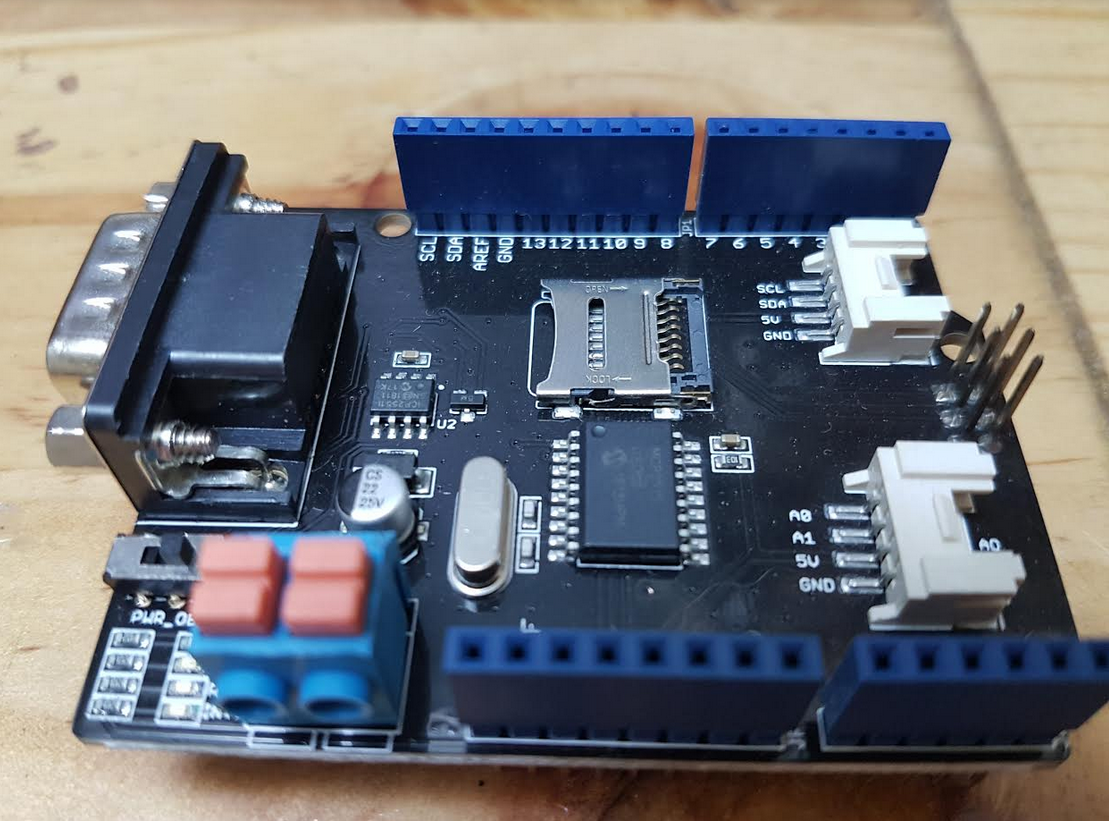
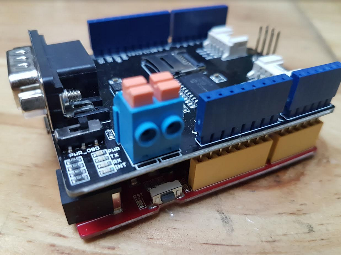
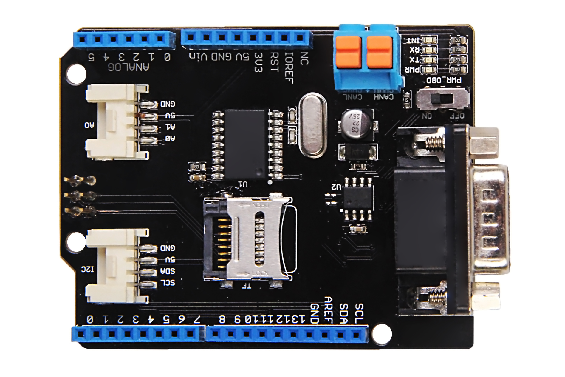
This instructable is meant for beginners who already know their way around Arduino. The initial know how to get going is always a pain and time consuming in any project. But until you know your way around you almost always wish you had someone to show you the basics.
In this instructable we will return some CAN-BUS data from your vehicle.
And don't worry! I will get right down to the point without rambling on and using buzz words to make me sound like a clever hacker :-)
I personally recommend the Seeed Studio CAN-BUS shields. Cant really speak for any of the other brands but the CAN-BUS Shield from SeeedStudio has served me very well.
Important Note: The can-bus shield is mandatory. I made this note because quite often people ask if you must use a CAN-BUS shield. The shield has an MCP2515 (CAN Controller) and MCP2551 (Transceiver) that will process CAN-BUS data to the serial port of your Arduino.
The Required Hardware.
1. Arduino UNO - Any arduino compatible will suffice. I used this one
2. SeeedStudio CAN-BUS Shield. I got it directly from SeeedStudio here's the link
3. Some wires to tap into the CAN-BUS
4. a Vehicle you can retrieve data from
The Required Software
1. Arduino IDE, Duh! Obviously :-)
2. SeeedStudio CAN-BUS Library. Downloadable from GIT Hub
Some extra vital information if you feel like reading more about the SeeedStudio CAN-BUS shield.
Let's get Started!
Hardware Setup and Connection
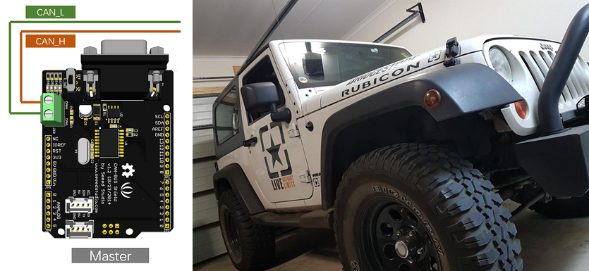

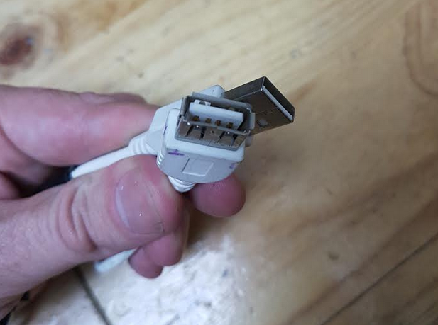
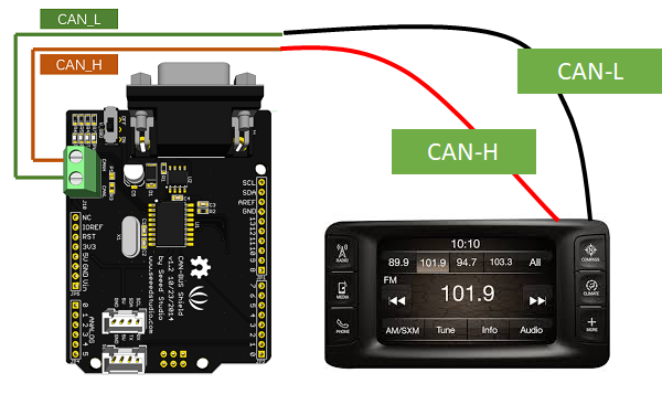
Let's start with the most difficult part. We have to find a place in your vehicle where we can tap into the CAN-BUS. There's not much I can do for you here, you have to figure this out by your self. In my case I tapped into the CAN-BUS via the radio. Yes! the radio. Vehicles with integrated car audio usually set the car-stereo display illumination based on the vehicle's headlamp setting for when driving at night. This is usually done via the Interior CAN-BUS.
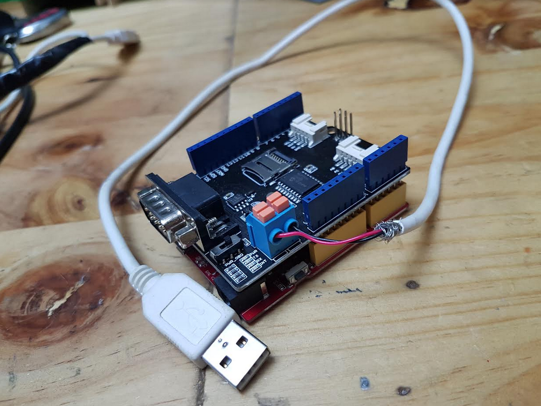
I used a USB extender cable that has a male USB and female USB end. So I simply cut it in half and then soldered the female side onto the radio's connector. You may want to buy a male female connector for your type of radio, that way you don't have to splice into your vehicle's wiring and void your warranty or potentially cause a fire hazard.
And then the male part I connected to the SeeedStudio CAN-BUS shield as shown in the picture. This way I can connect/disconnect when needed.
Tip: Use red wire for CAN-H and black for CAN-L
Install the Software Onto the Arduino.
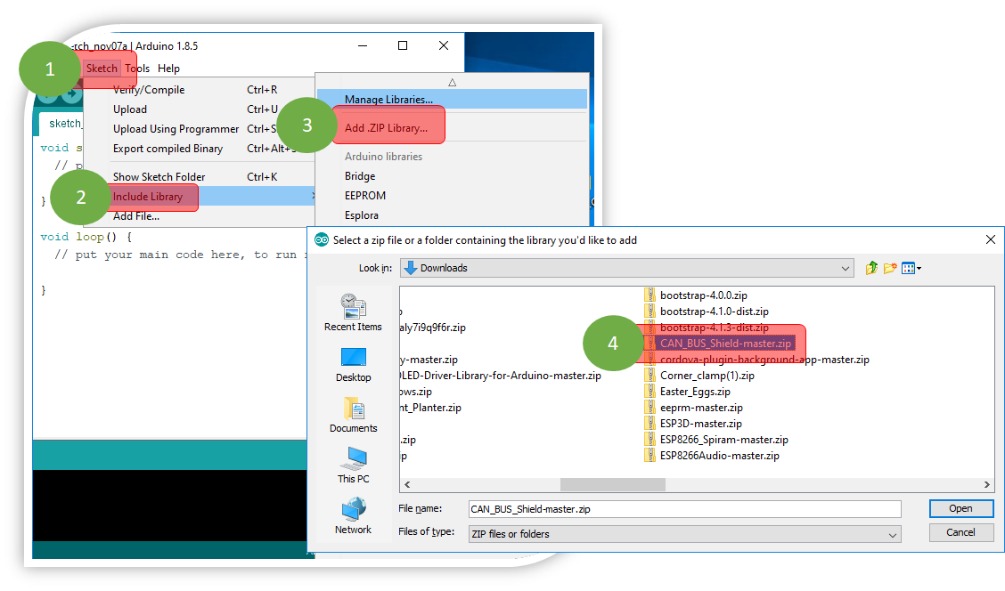
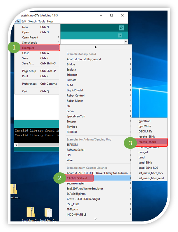
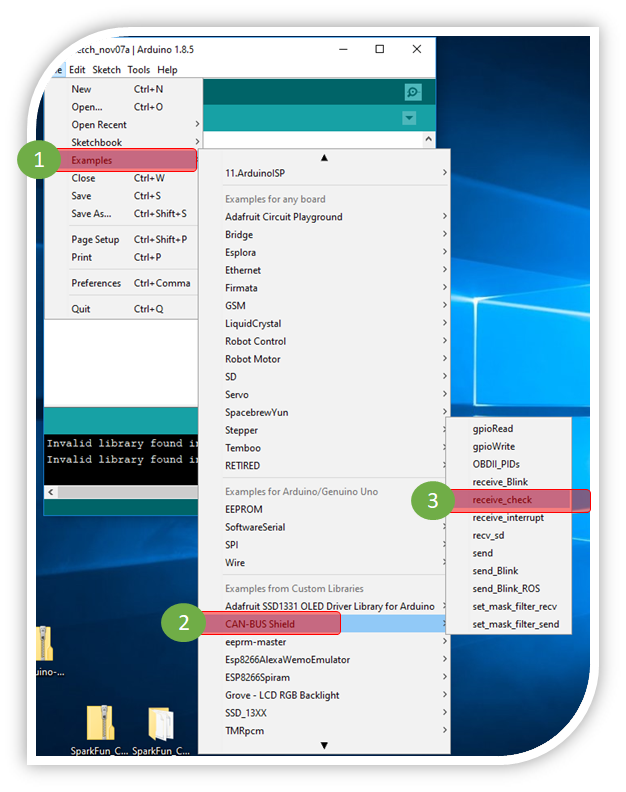
Download the SeeedStudio Library from the SeeedStudio CAN-BUS wiki.
https://github.com/Seeed-Studio/CAN_BUS_Shield
Install the library as show in the pictures.
From the Arduino IDE select Sketch --> Include Library - Add .zip Library.
After adding the library close the Arduino IDE and reopen it. You will now be able to load some of the examples from the File Menu File --> Examples --> CAN-BUS shield --> Receive check
For this tutorial load the receive check example.
Important!
The following will require some trial and error.
I used my Jeep JK 2010 Rubicon to retrieve data and it's interior bus runs at 125Kbs.
In the setup section where it reads
while (CAN_OK != CAN.begin(CAN_500KBPS)) I had to change it to
while (CAN_OK != CAN.begin(CAN_125KBPS))
If you get this wrong you will not be able to retrieve readable data. In in most cases including mine your vehicle will go bonkers. I.E the cluster with light up like a Christmas tree and the wipers will start to move. because the can bus shield is corrupting the bus.
Connect It and Start Retrieving Data
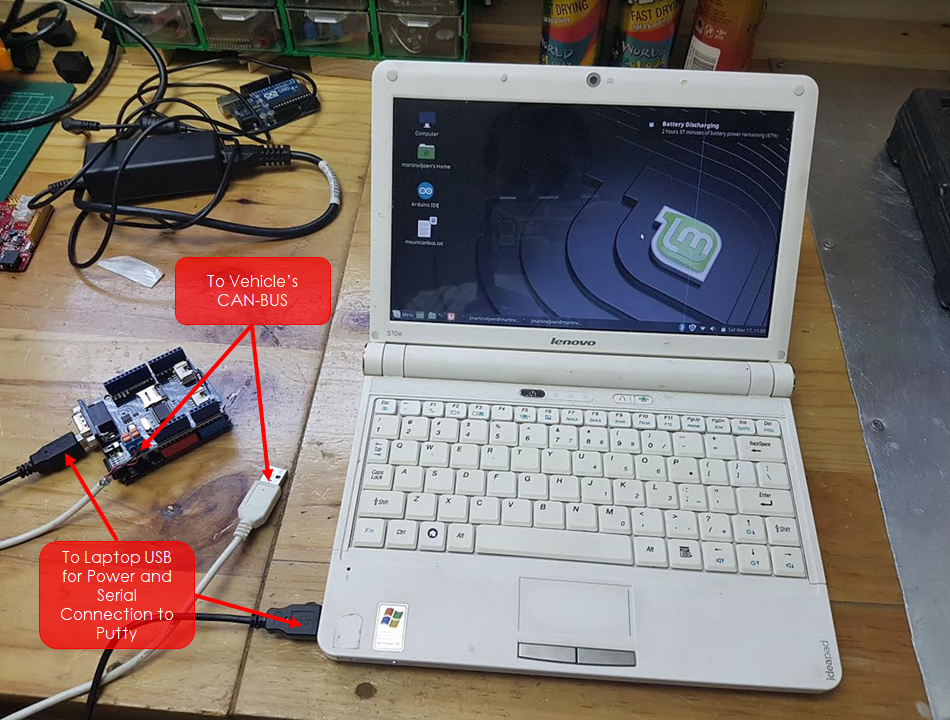
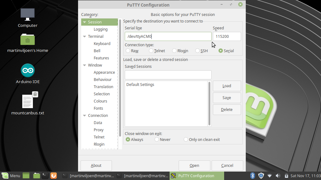
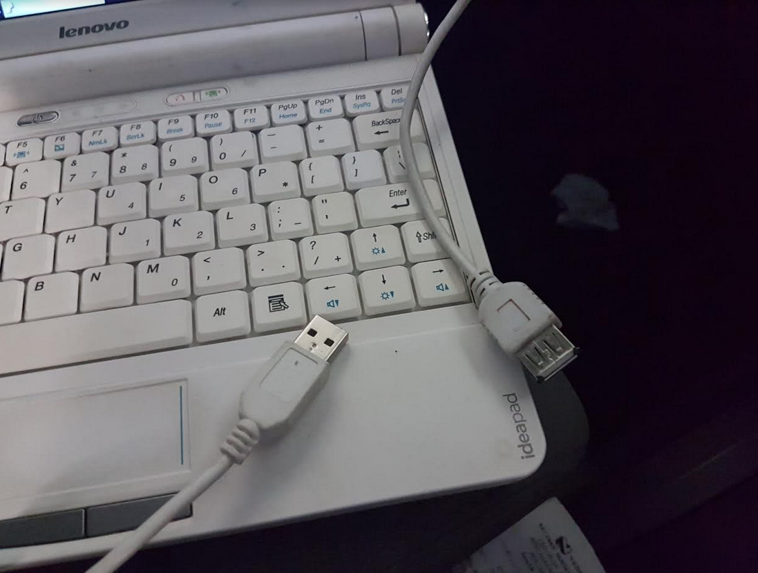
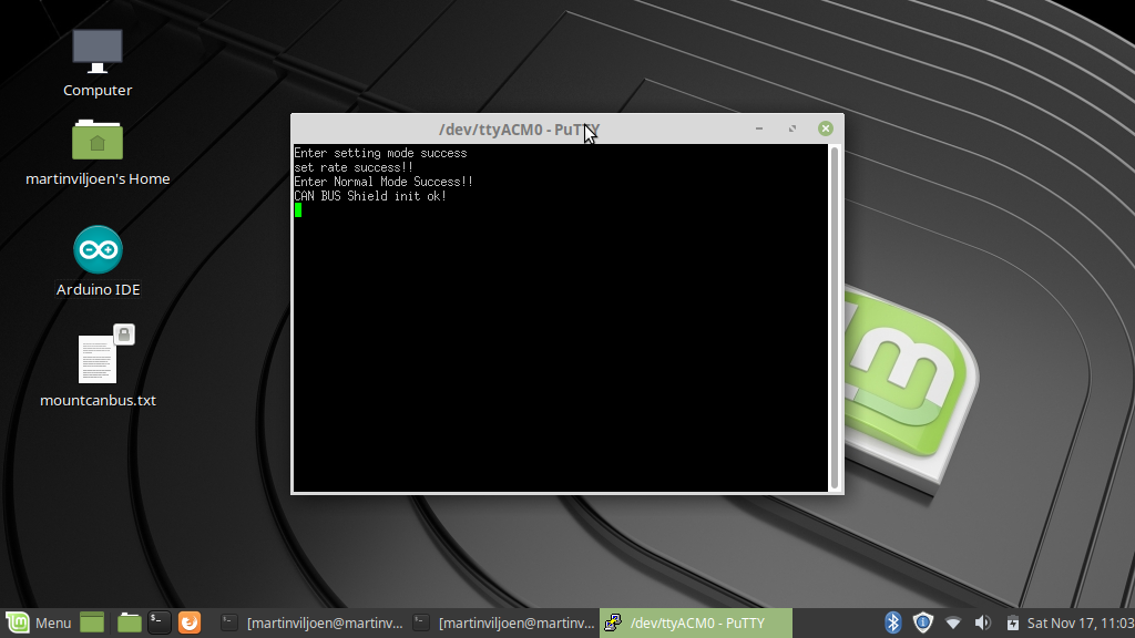
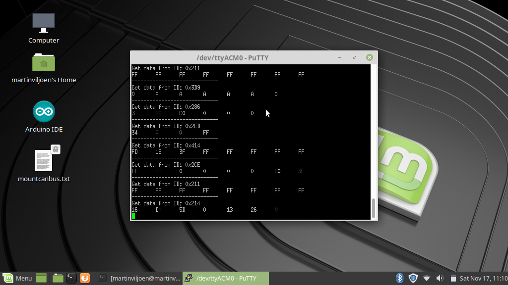
Before you connect please take a sanity check before you hook it up to your vehicle. The last thing you want to do is, send power to your CAN-BUS potentially blowing your Vehicle's ECU.
I did not do a sanity check and only after I realized i'm not getting data did I see I connected the Laptop's USB directly to the Arduino's USB Power. Luckily nothing happened.
In the pictures of this step I used my Lenovo Laptop loaded with Linux Mint. Off-coarse you can use any operating system to connect to your Arduino's serial port,
1. Setup the laptop in your vehicle and power up the Arduino CAN-BUS shield with a USB cable.
2. Start Putty or the Arduino serial Monitor (I prefer Putty), When its connected you should see a message in the serial console telling you that it managed to initialize the Can-Bus shield.
3. Turn on the vehicle. It doesn't have to be started as long as the key is in the on position.
4. Connect the Arduino to the CAN-BUS. The moment its connected the data will start to stream into the console.
The Data and What It All Means
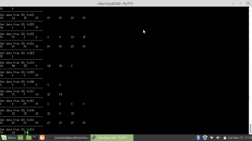
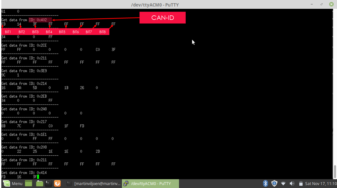
When the data is retrieved it will dump it into the following HEX format.
ID, BIT1, BIT2, BIT3, BIT4, BIT5, BIT6, BIT7, BIT8
The ID usually represents a Node within your vehicle.
Let's make a simple example. (The below is made up and not real, just an example)
Air Conditioning Node ID= 0x402
TURN AIRCON OFF = 13
TURN AIRCON ON = 14
SET AIRCON BLOWER TO LOW = 7C
SET AIRCON BLOWER TO MEDIUM 8C
SET AIRCON BLOWER TO HIGH 9C
So if we turn on the Aircon and set it on medium the message will look like this
0x402, 13, 8C
the same goes for other nodes, example Central Locking
Central Locking ID= 0x503
LOCK all doors = 14
So if you press the button to lock all doors the message will look like this
0x502, 14
Some Extra notes.
Some messages are state driven and some or momentarily.
Example1. Head lamps as state driven. When you set a switch in the vehicle to a specific position the node will keep broadcasting the message over and over. If you had to interfere with the CAN-BUS an send a message to turn off the head lamps. It will briefly turn off and then on again because the node where the switch is set to turn on the headlamps will again send a message to turn it on.
Example2. Skipping tracks on your radio head unit. when you press a button and its a momentary button that will make and immediately break the circuit when you leave it, It will send one message to skip the track and never again until you ask press the button again.
Usually momentary buttons are the most useful because you can control features in your vehicle by sending a single command without having the worry that your command will be over written. Where as state driven features will be overwritten indefinitely.
Some tips and ideas.
Seeing you are now able to dump the data you can use it to build your own Arduino circuits that will react based on the messages is see on the CAN-BUS. for an example. Say you install after market spot lights. Without having to dig into your existing wiring you can install your headlamps independently and only turn them on when your Arduino detects a message on the CAN-BUS.
Sending data into the CAN-BUS.
If you followed the instruction in the beginning of this instructable you have installed the SEEEDStudio libraries.
In the Arduino IDE there are some example you can try out.
Knowing the ID and the CAN0-BUS message of the node that you want to interact with.
Unfortunately this is not a very easy task. But here's an Idea. Use Putty's Logging feature and dump all session data to file. Let the Arduino monitor the can bus for about 5 Mins and then save the log out the way.
Then start a new session and start dumping the data. But this time while its dumping the data press a button. Don't press more than one button. Press the button a couple of times to guarantee that it captured the button press.
Then use some sort of comparison tool and compare the file to spot the differences. Excel works great for this.
Some Codes you can try
If you have the same Jeep 2010 Rubicon model as me (I'm sure the below will also work for models '07, '08' ,09)
You can try the following messages. Load the send examples from the Arduino examples menu and change were relevant.
Engage Rear Locker.: CAN.sendMsgBuf(0x2B0, 0, 4 ,stmp);
Left Blinker On: CAN.sendMsgBuf(0x2A8, 0, 6 ,stmp);
Right Blinker On: CAN.sendMsgBuf(0x2A8, 0, 6 ,stmp);
ESP On/OFF: CAN.sendMsgBuf(0x2B0, 0, 4 ,stmp);
In my next instructable I will be sending some data to my Jeep's CAN-BUS to demonstrate how you can interfere with it.
Good Luck!
Watch the Video

See the video for more CAN-BUS goodness!