Security Door Lock

Hello, This is my Security Door Lock
The purpose of my project is for it to firstly act as a normal door lock where when you press the button the lock opens and you are able to open the door. Once unlocked you have a certain period of time till the door locks again. The lock also has a built-in distance sensor letting you know if anyone or anything is at the door through the help of an LCD and RGB LED. There is also a night light that turns on whenever it doesn't sense light
Supplies


Yellow LED(1) https://www.sparkfun.com/products/9594
Pushbutton(1) https://www.sparkfun.com/products/97
Distance Sensor(1)https://www.amazon.ca/HC-SR04-Ultrasonic-Distance-...
RGB(1) https://www.sparkfun.com/products/105
LDR(1) https://www.sparkfun.com/products/9088
Servo Motor(1) https://www.sparkfun.com/products/9065
LCD(1) https://www.sparkfun.com/products/255
330 Ohm Resistor(2)https://www.amazon.ca/dp/B07FYJFLL8/ref=sspa_dk_de...
10000 Ohm Resistor(2)https://www.amazon.ca/Projects-100EP51410K0-10k-Re...
Breadboard(1)https://www.amazon.ca/Breadboard-Solderless-Protot...
Research
In order to determine my project direction, I extensively conducted research by exploring various examples of circuits created and shared by other individuals.
During this process, I came across two particular circuits that really intrigued me.
https://projecthub.arduino.cc/Krepak/ultrasonic-security-system-a6ea3a
https://projecthub.arduino.cc/agarwalkrishna3009/f7ad02bb-8fc6-4c33-8e1d-3d52a3043282
After reviewing both circuits, I decided to create a project with a focus on security and incorporating a distance sensor. Using all the ideas from those circuits I was first ready to make a security doorbell but due to a lack of supplies, I had to change my idea into a door lock using a servo motor instead of a buzzer. From there it was a simple and clear path of creating my own circuit that would meet all the requirements given.
Wire the Circuit

.png)
.png)
.png)
.png)
.png)
Now after all the research and gathering all the supplies needed lets wire the circuit. You can use the pictures above as a reference and also the direct instructions below
Distance Sensor
Power to Power Pin
Ground to Ground Pin
2 to Trigger
3 to Echo
LED
Negative to Cathode (Using 330 Ohm Resistor)
5 to Anode
Pushbutton
Positive to 1b
Negative to 2b (Using 10k Ohm Resistor)
6 to 2a
RGB LED
Positive to Anode (using 330 Ohm Resistor)
11 to R (First Leg)
10 to G (Third Leg)
9 to B (Fourth Leg)
LDR
One Leg to Negative (Using 10k Ohm Resistor)
Other Leg to Positive
Negatively Charged Leg to A0
Servo Motor
Red Wire to Positive
Brown Wire to Negative
Orange Wire to 13
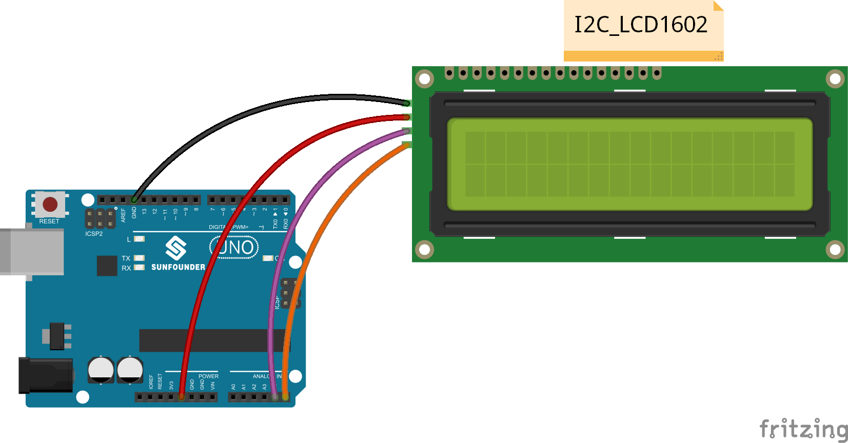
LCD
GND to Negative
VCC to Positive
SDA to A4
SCL to A5
How It Works
This circuit operates by utilizing a distance sensor that constantly provides a measurement in inches, indicating the proximity of the nearest object. This information can be utilized to detect the presence of individuals nearby or to identify the presence of a package on the ground. The distance sensor emits a signal which reflects off the closest object and returns to the sensor. By analyzing the travel distance of the signal, the sensor is able to determine the proximity of the object. The way you will be able to read the distance is from the LCD but you will also get a rough estimate from the RGB LED
There is also the Pushbutton, this button is what the actual door lock is dependent on. When this button is pressed it will activate the servo motor causing the door to become unlocked. If the button is not pressed the door will stay locked no matter what. The way the button works is that when the button is pressed the spring on the inside makes contact with two wires which ultimately lets electricity flow
The Servo Motor is very simple as it works directly with the pushbutton. As I just said when the button is pressed the servo is then directed to move out of the way of the door causing the door to be able to open up. A servo motor in Arduino works by receiving control signals from the Arduino board, which determine the desired position or angle of the motor shaft, allowing for precise and controlled movement.
The LCD in this circuit has only 1 thing to do and that is to display the distance that is getting inputted from the distance sensor. It will display this by saying "Distance:" and then right below it the number in inches. The LCD in this circuit is only connected to power, ground, and two analog pins on the Arduino. The way that the LCD works is it functions by utilizing liquid crystal molecules that align or block light to display characters or graphics when an electrical voltage is applied, allowing for the visual representation of information or data.
In this circuit, the RGB LED shows you approximately the distance that is being sensed from the distance sensor. If the distance is 5 and below the RGB will be red, if it's in between 6 and 15 it will be blue, and if it's over 15 it will be green. This makes it even easier to tell if there is something to someone at the door, in the dark, and from across the room. An RGB operates by combining different intensities of red, green, and blue light emitted from three separate LED elements within the component, enabling the generation of a wide range of colors by adjusting the intensity of each individual color.
Lastly, there is the LED and LDR, and both these components work hand in hand with each other. In this circuit these two work with each other to create a kind of night light system. The LDR senses is there is light being transmitted towards it weather that is artificial or solar. From that, if it is not sensing any light it will send a signal over to the LED and instruct it to turn on so that the front door is illuminated. If it senses there is light it will not instruct the LED to turn on. The LED emits light when electricity flows through in one direction and an LDR works by altering its resistance in response to varying levels of light, allowing it to detect and measure the intensity of light in its surroundings.
Code Info
Plug your Arduino Uno into your computer and open up the Arduino Application. Once open download the code and open it with that application then Upload it to your Arduino.
When you open the code you will see a lot of int ####. These are the variables where you say what pin each component is connected to
After all the variables are declared you will see something called void setup. Void setup is where you will have to declare each component as an Input or Output
After that there is the void loop which is the main code that is to be repeated over and over again (in a loop)
In my code I have it organized in such a way that you can easily see what code is for what components as there are multiple void functions for the different features in the door lock.
One important thing you may need to know is that after a certain amount of time after the button is pressed the door locks on its own again. This can be edited within the code by just changing the delay time in between angle changes.
This video below shows the lock of the actual door in motion ↓
https://drive.google.com/file/d/12TwklrF3m_JmTW0sZ9eoqkbhkTIqG2-g/view?usp=sharing
You can download the code for my circuit below ↓