Screwdriver and Plier Tool Holder Pockets Cut on CNC
by wrt54gfanatic in Workshop > CNC
2718 Views, 28 Favorites, 0 Comments
Screwdriver and Plier Tool Holder Pockets Cut on CNC
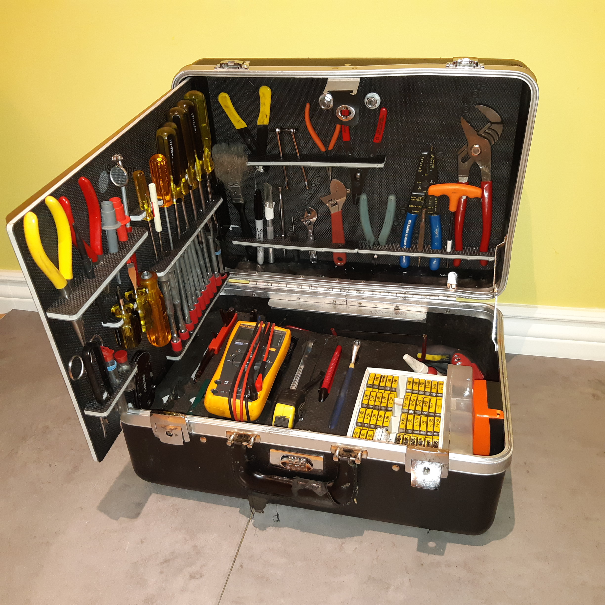
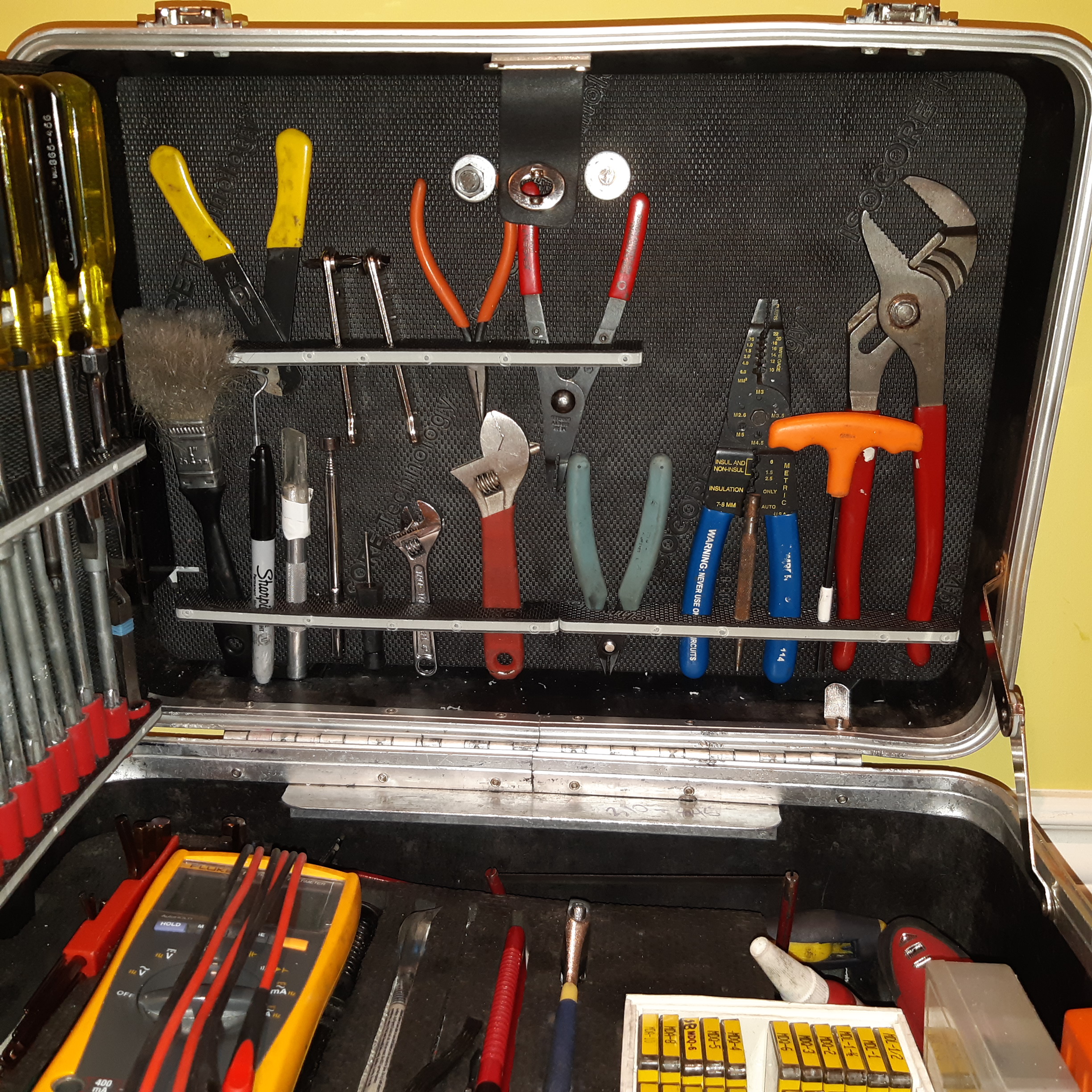
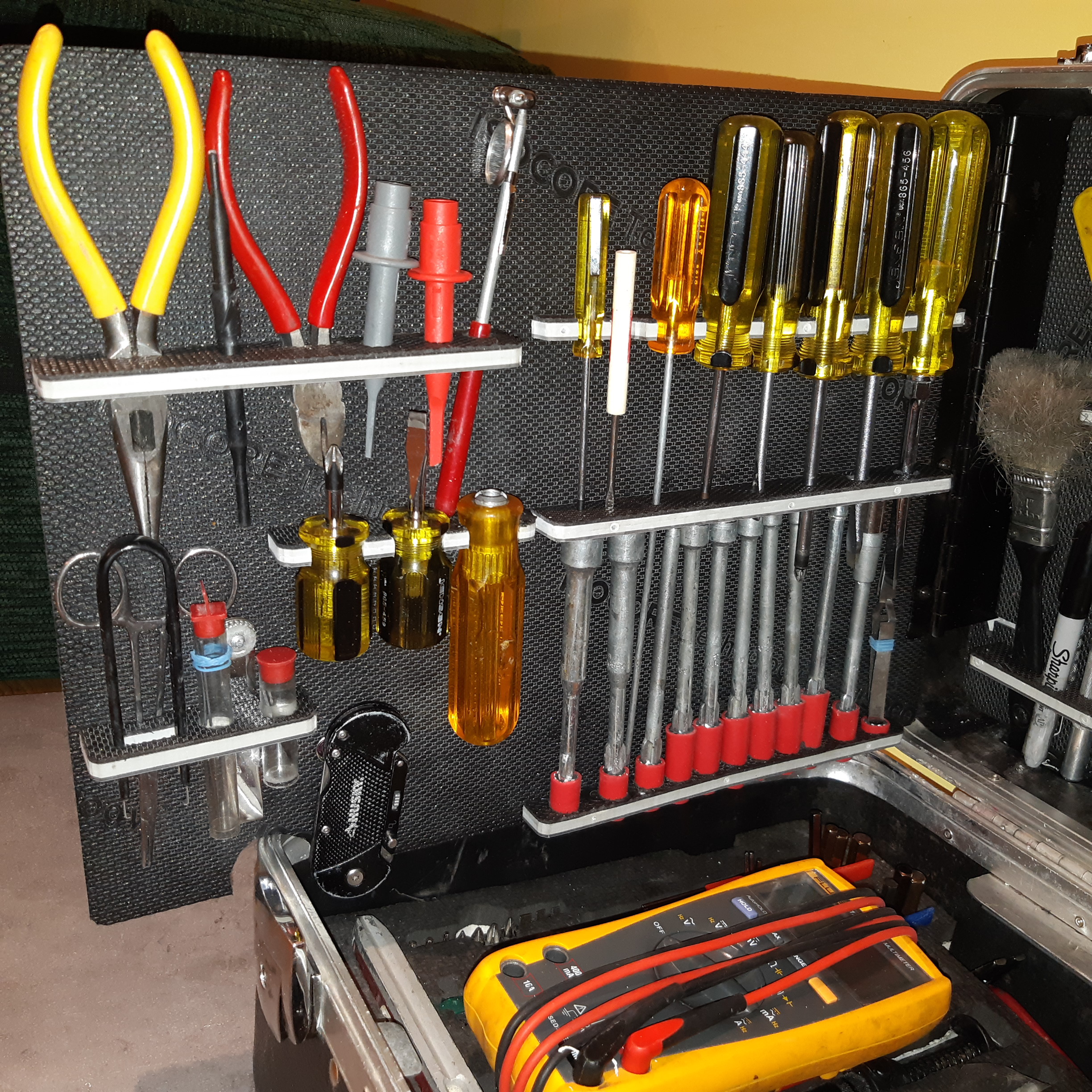
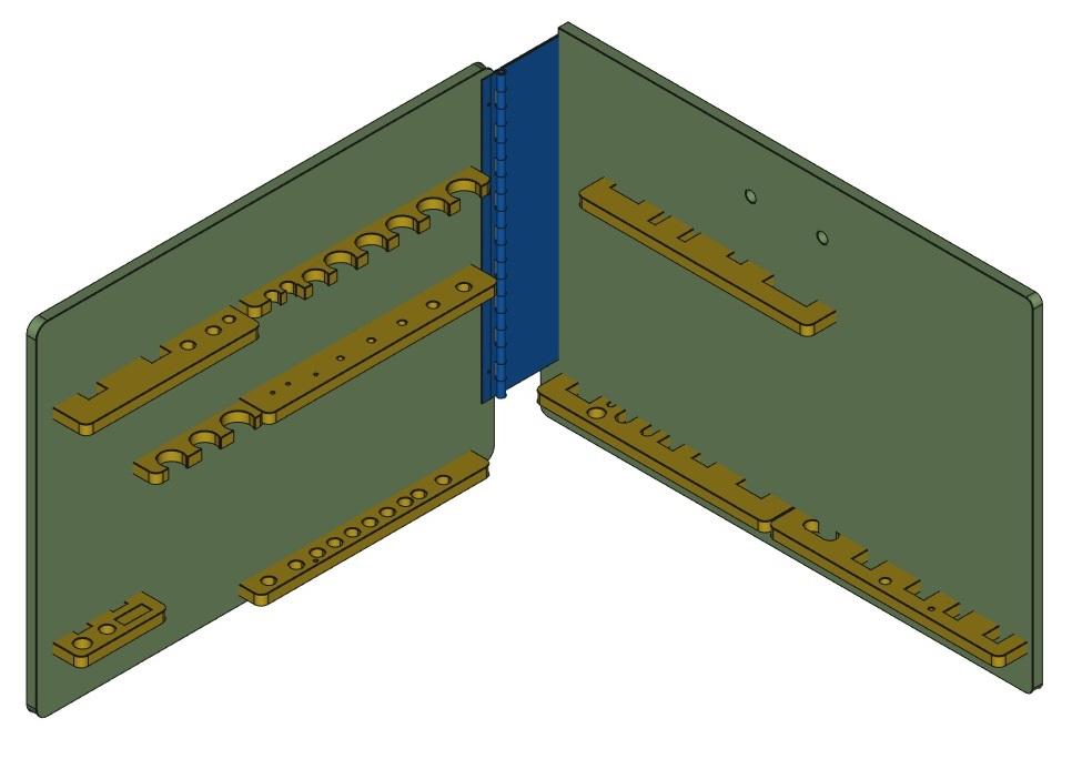
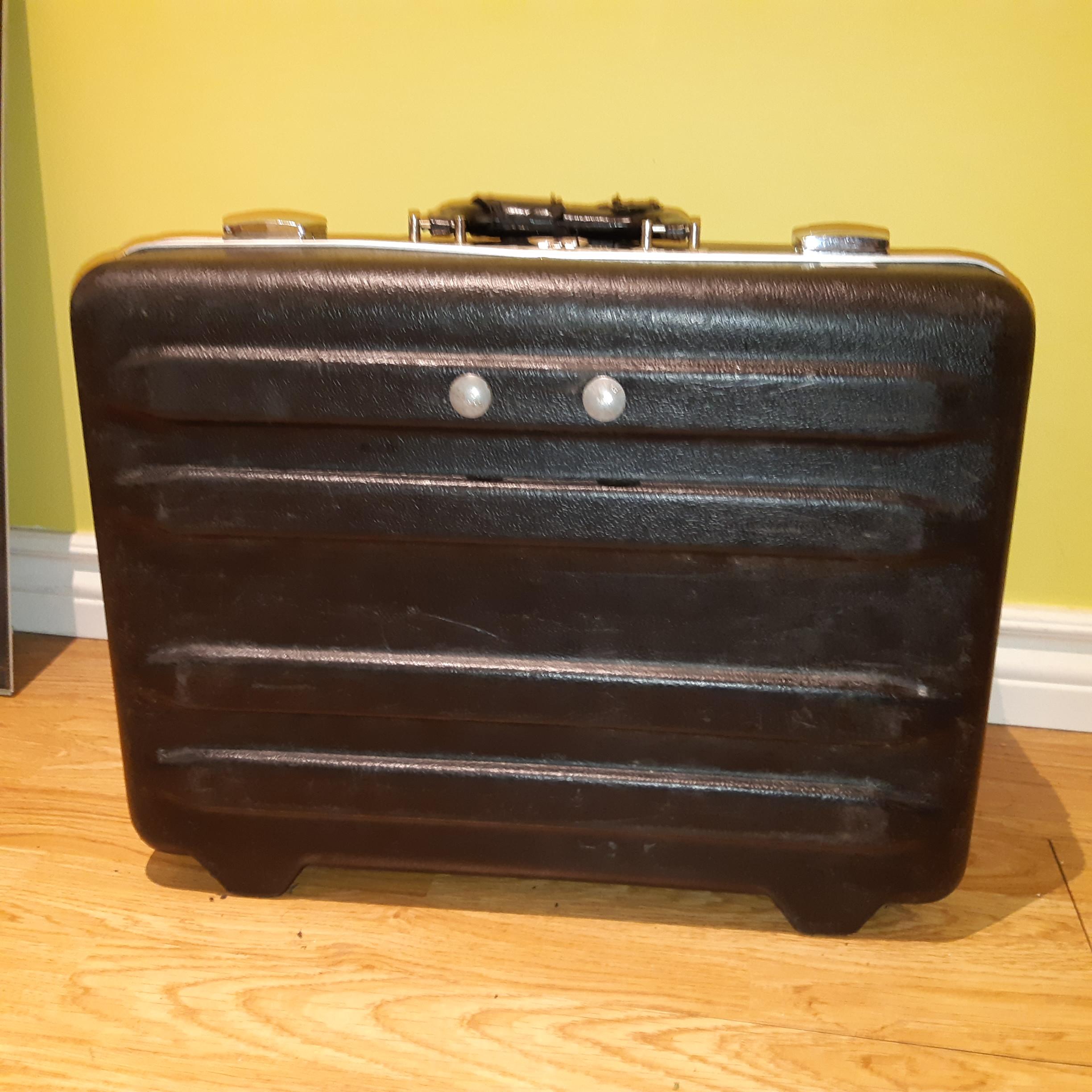
The aim of this project was to build replacement tool holders for for screwdrivers and pliers.
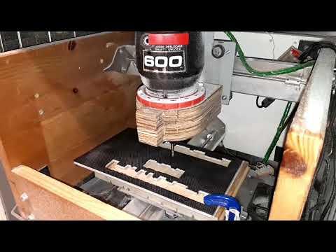
This was done using a Sienci CNC machine, FreeCAD, and The Universal Gcode Platform, and surplus vinyl tiles.
If given the chance to do this project again, it would be much easier with Fusion360.
Cut Out the Backer Boards
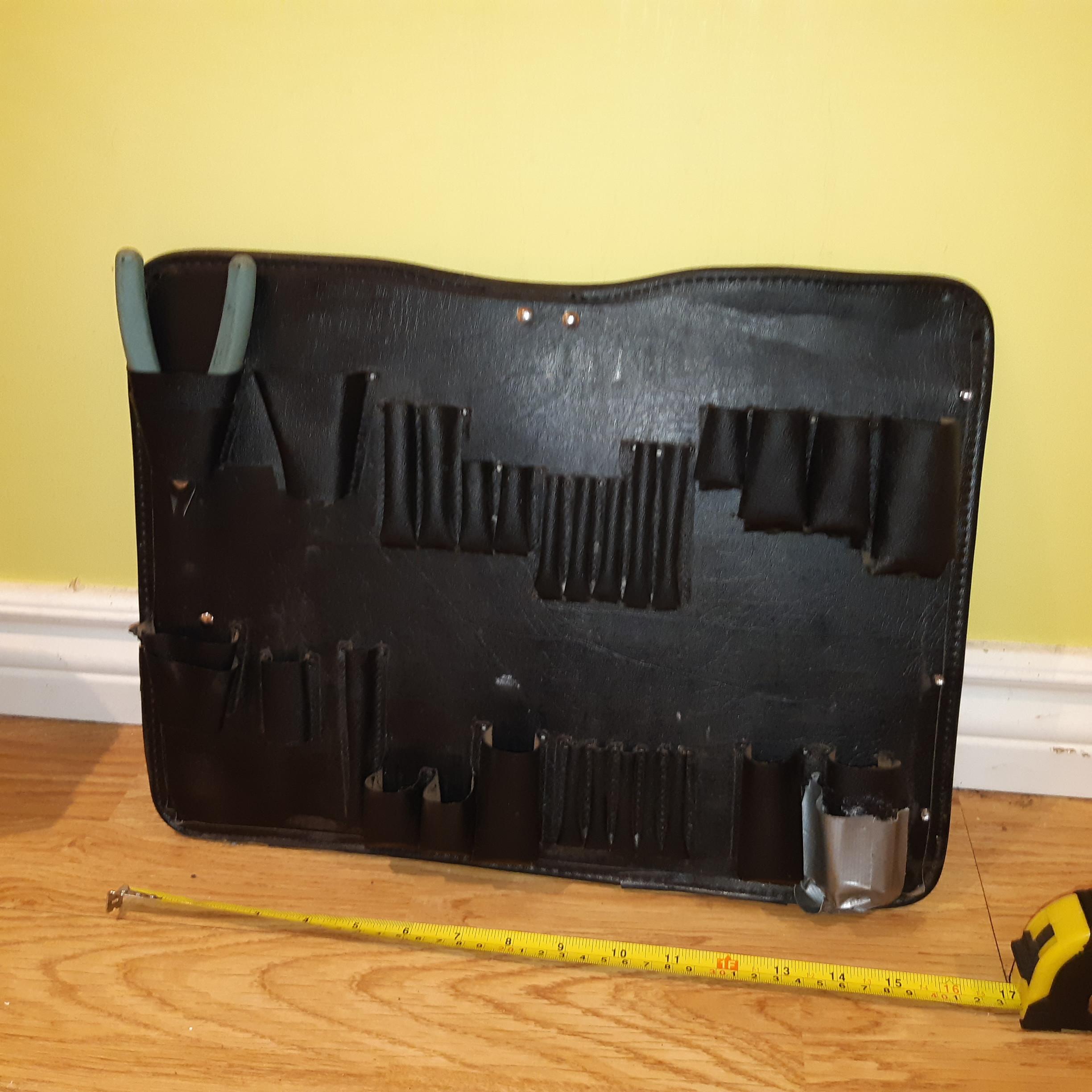
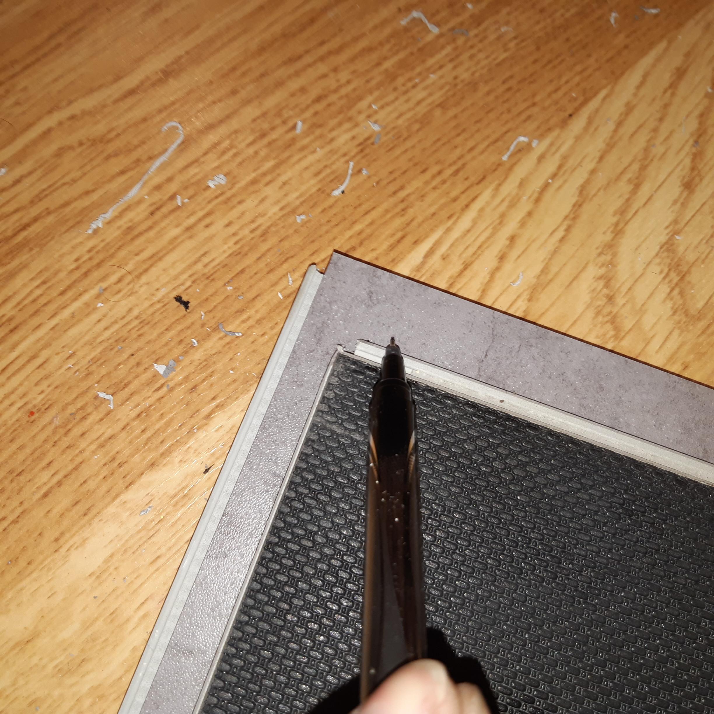
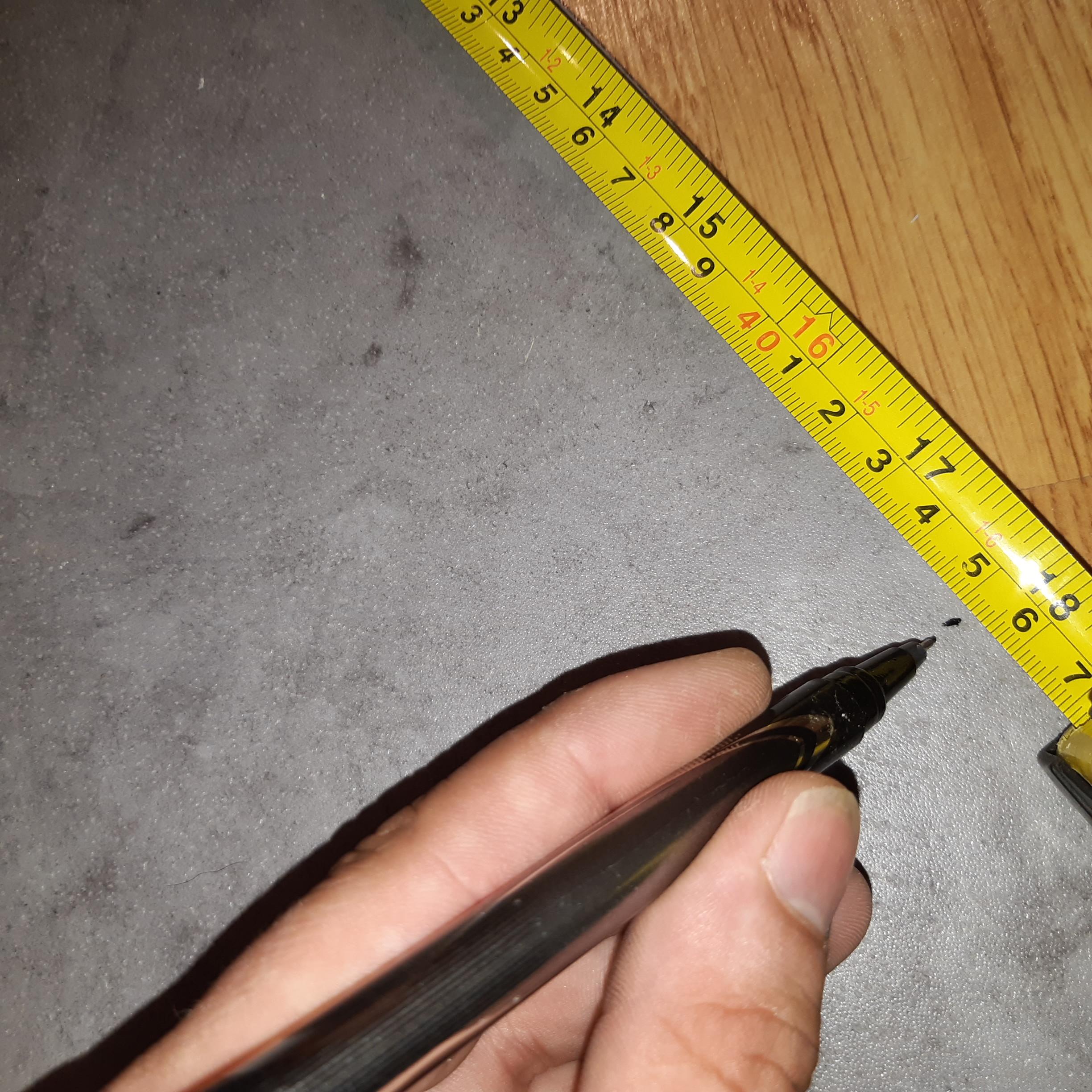
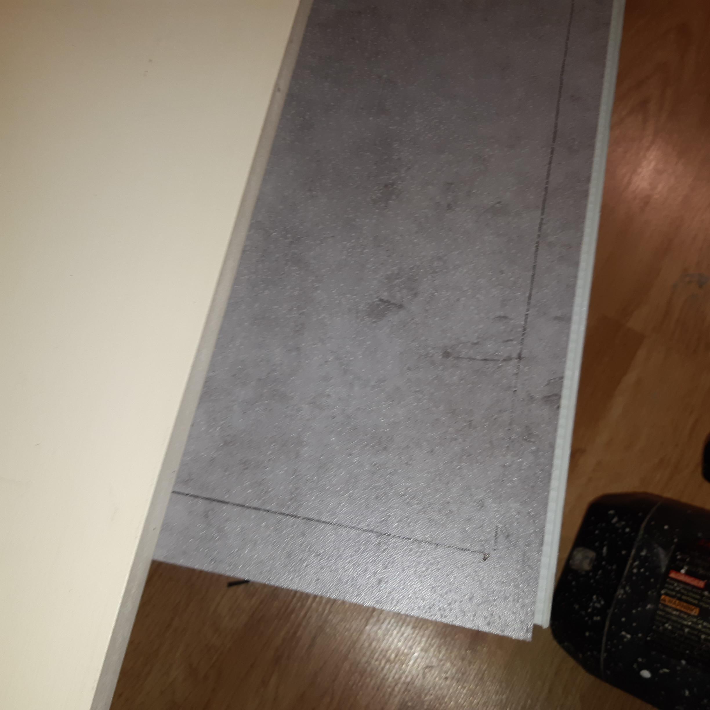
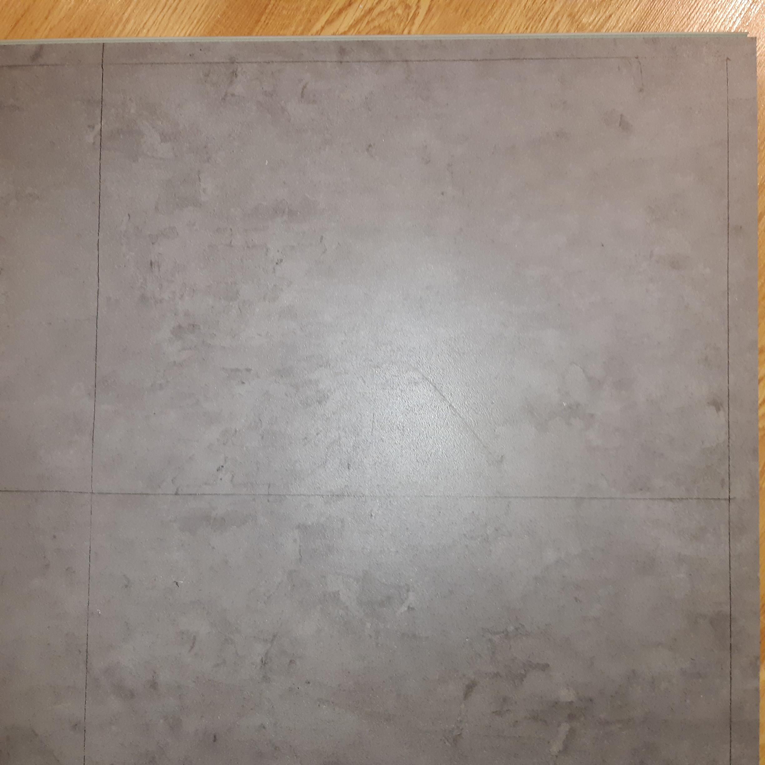
Measure existing tool pocket backer board length and width.
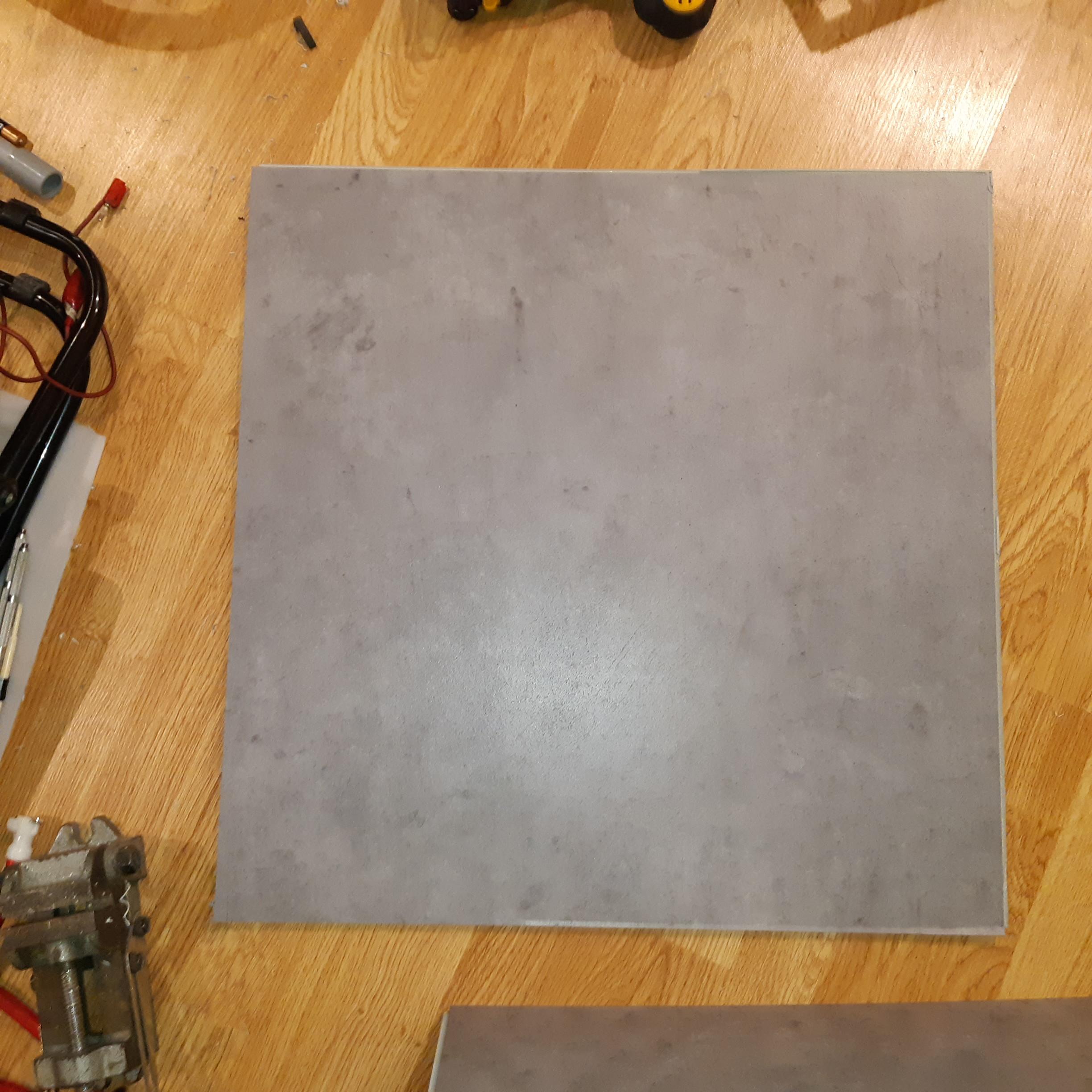
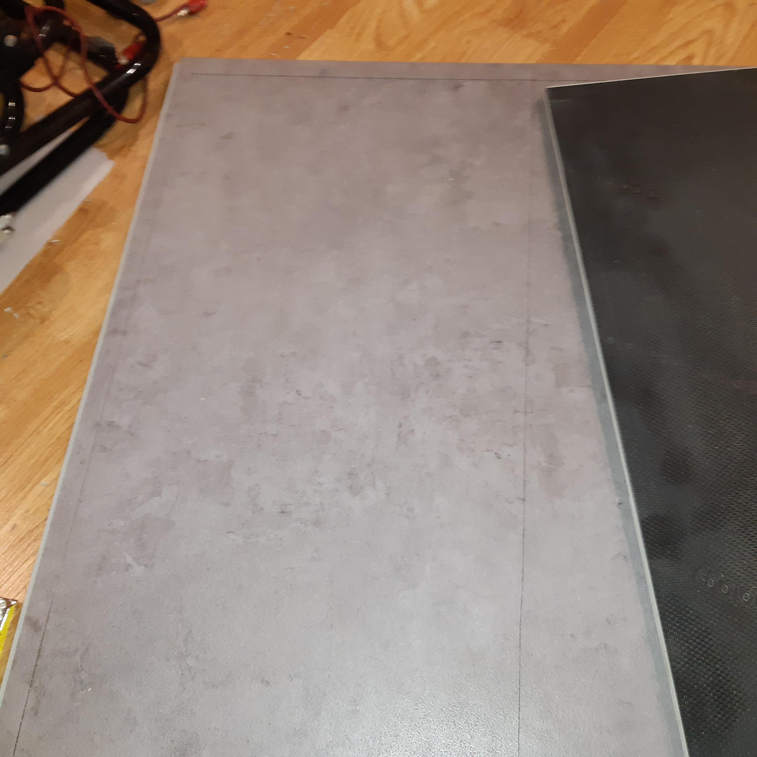
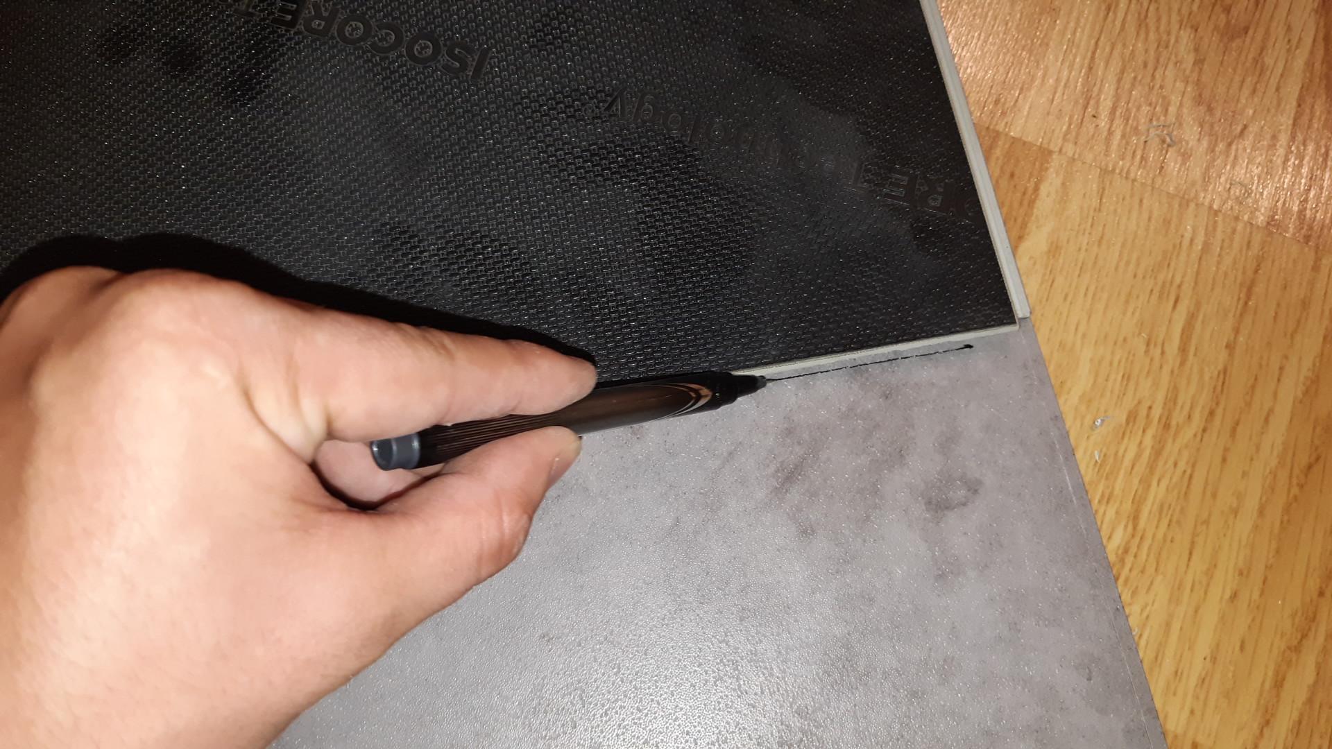
Draw the tool pocket dimensions on vinyl tile with a fine point marker, pencil or pen. Another tile was used as a straight edge. Draw the Rounded corners.
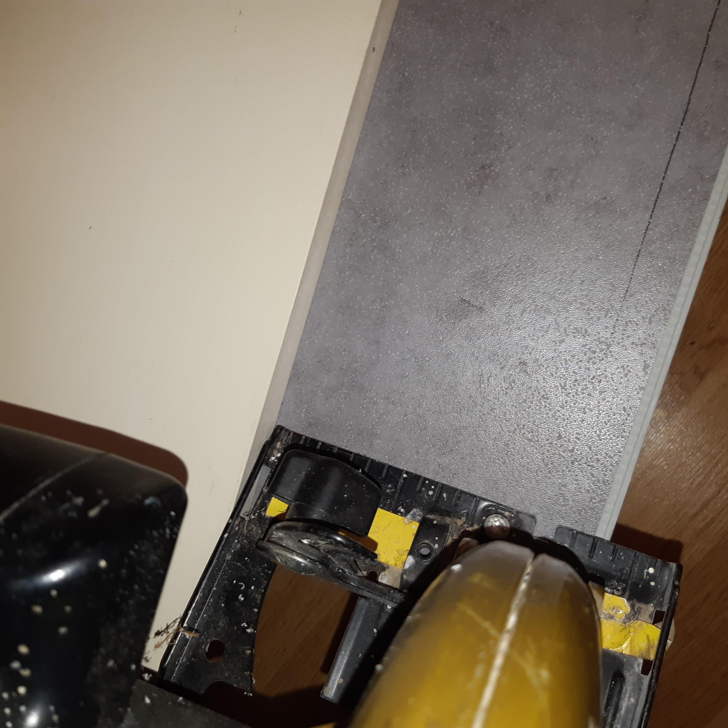
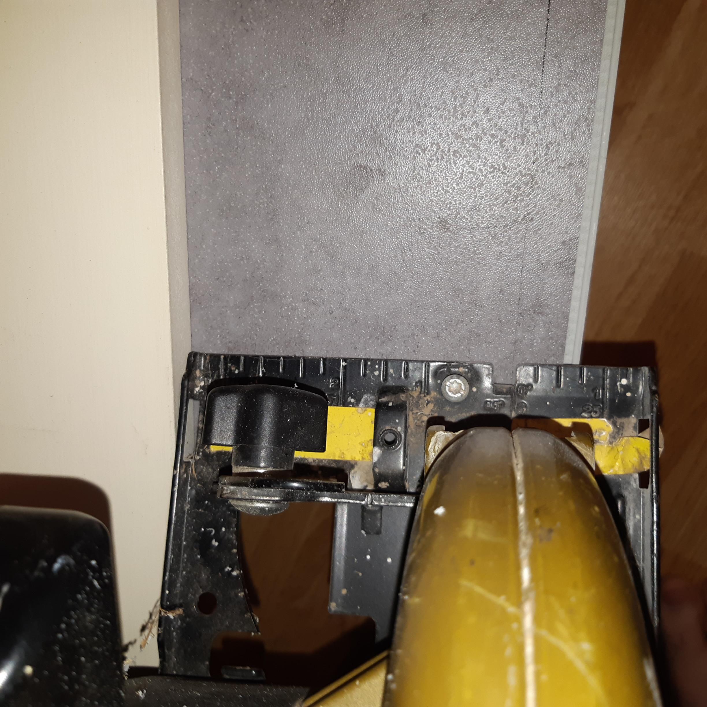
Cut out vinyl tile on a handheld circular saw use a straight edge and clamps.
Cut out the rounded corners with an electric jigsaw.
Design the Tool Pocket Shelves
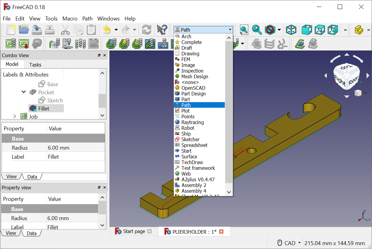
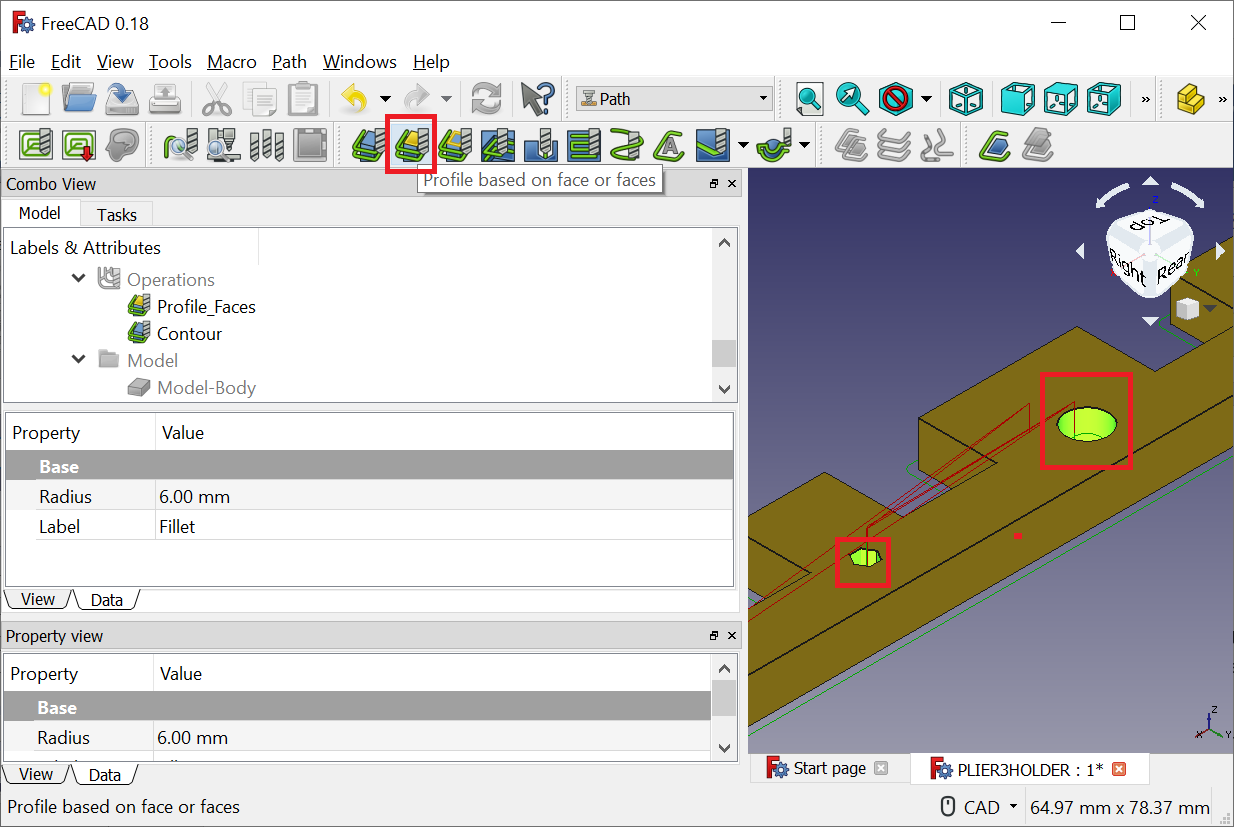
Determine the maximum object dimensions your CNC can cut.
Lay out the tools on the tool pocket board to determine most frequent use, and optimum spacing.
Open an existing FreeCad part that has a Path Job Setup.
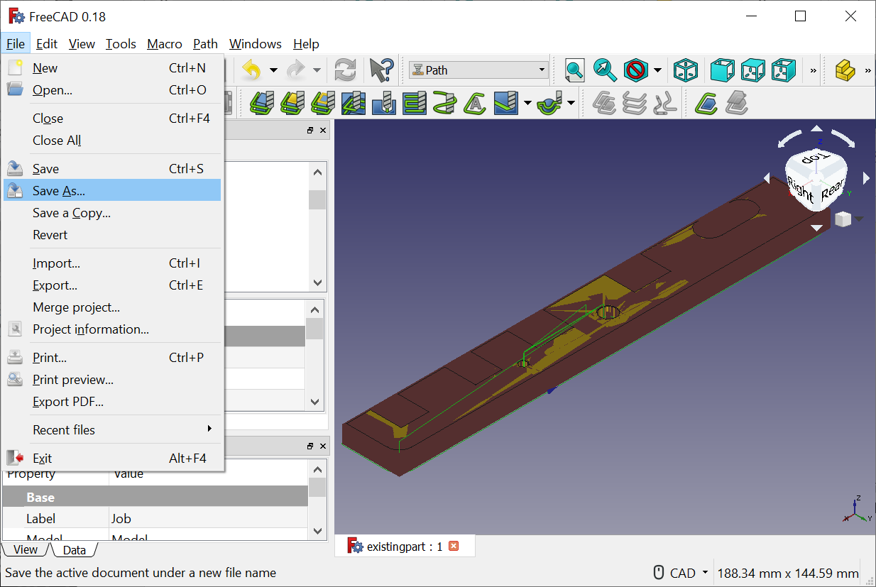
Save the part as a new file name.
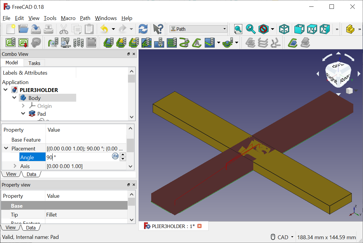
Depending on your CNC Work Envelope, it may be necessary to rotate the part, this is done by clicking the Data Tab on the Body Object in the Tree, and typing in 90 degrees under Placement Rotation. This may need to be repeated under Job, Model-Body
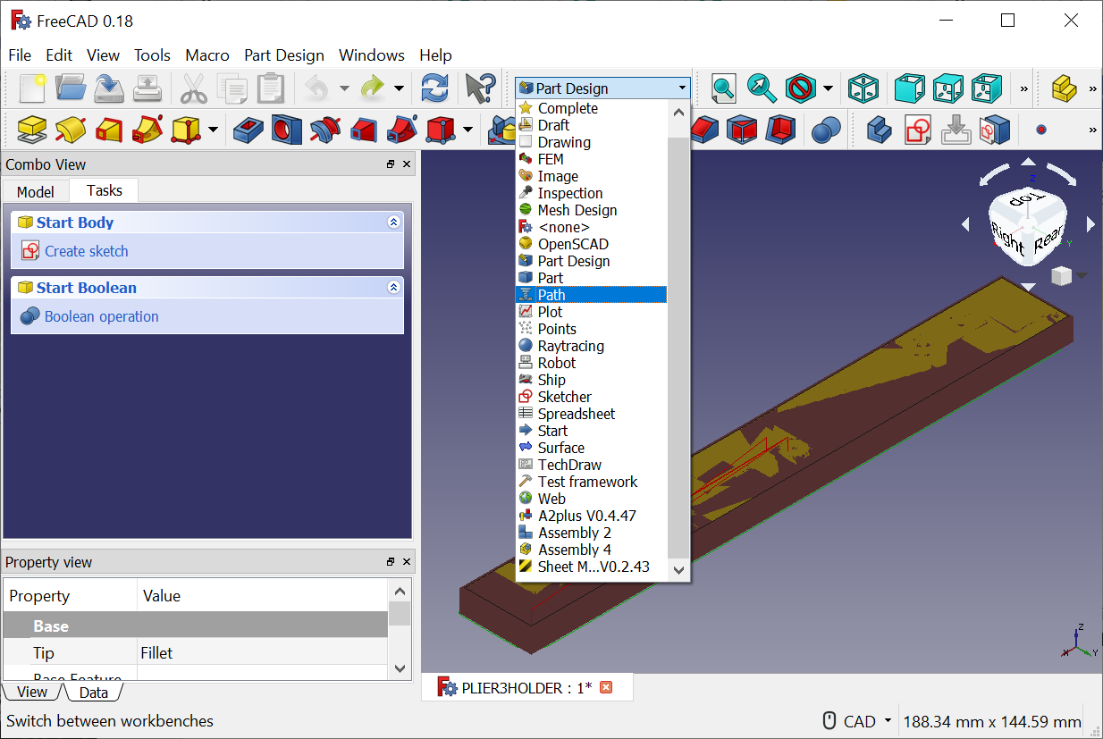
Switch to the Path Workbench
Edit the Path Job:
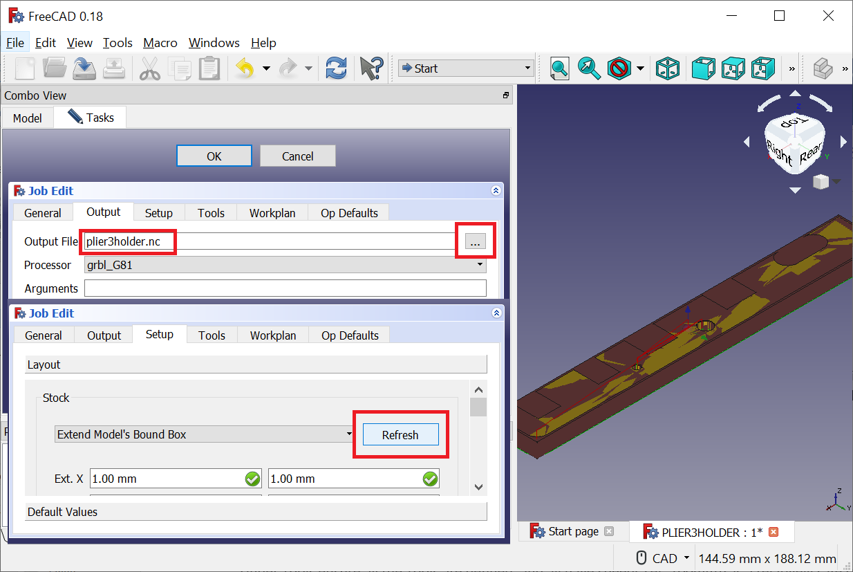
- Set the Output to the gcode filename you wish to use, select GBRL_G81 post proecssing
- Under Setup, press Refresh to Extend the Model’s Bound Box
- Under Tools ensure all the Tools are defined, and all have speeds set, 100mm/s is a relatively safe speed.
- If necessary, under Workplane, the Job cutting operations can be reordered.
- Resize the tool holder shelf to be large enough to fit the determined tools.
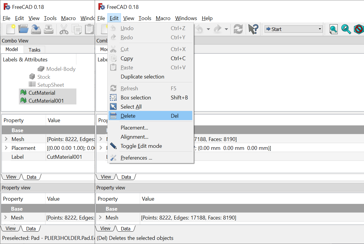
- Delete the CutMaterial objects from the tree as these will be regenerated later, and they obscure the part.
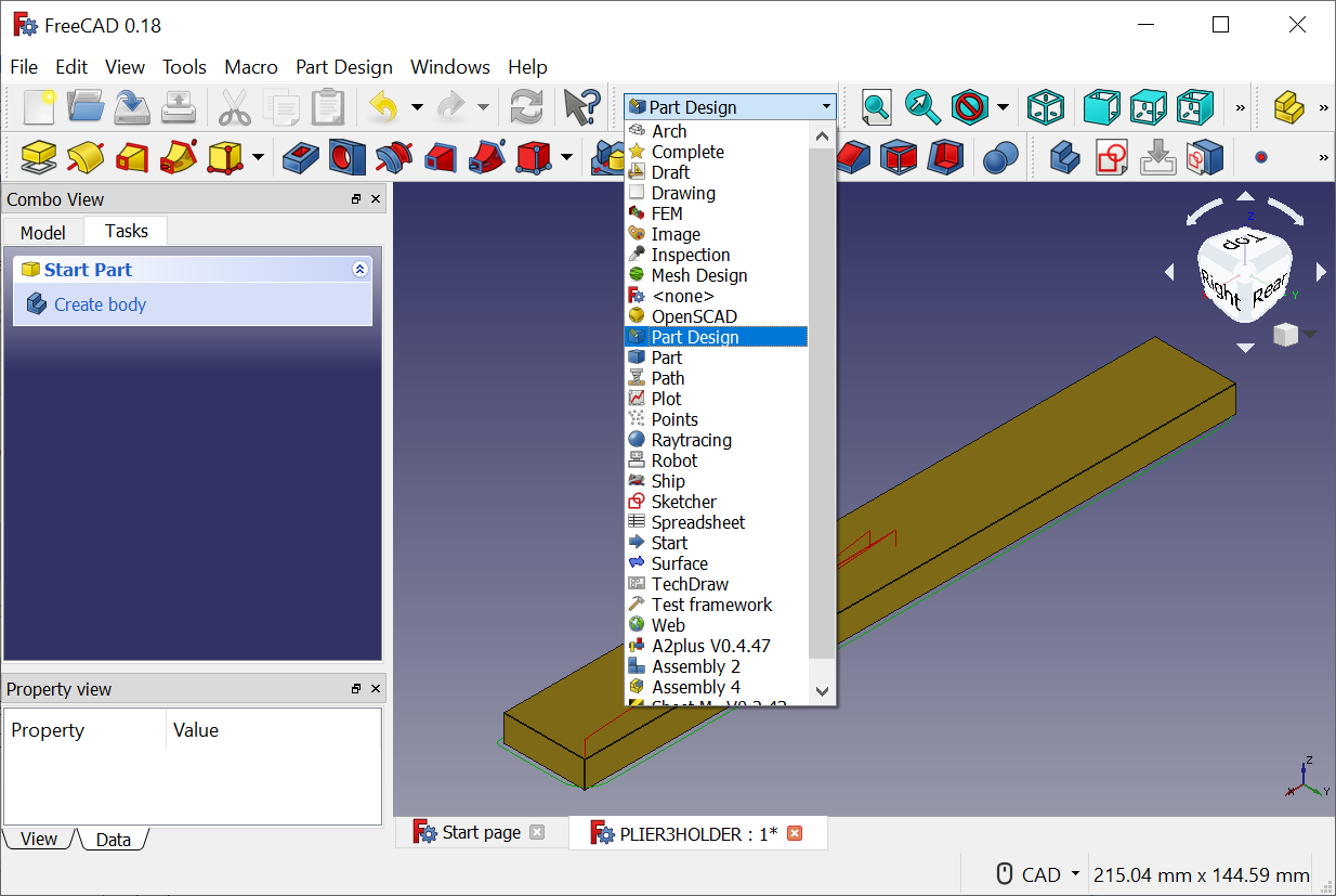
Switch to the Part Design Workbench
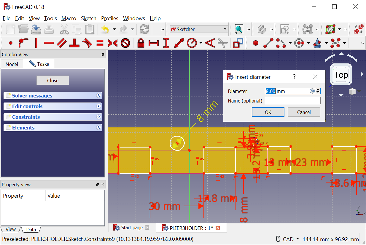
Measure the openings required for the tools with a caliper to determine the opening size. Make the hole large enough to fit the tool, but not too large. About 0.5mm larger usually worked on this build.
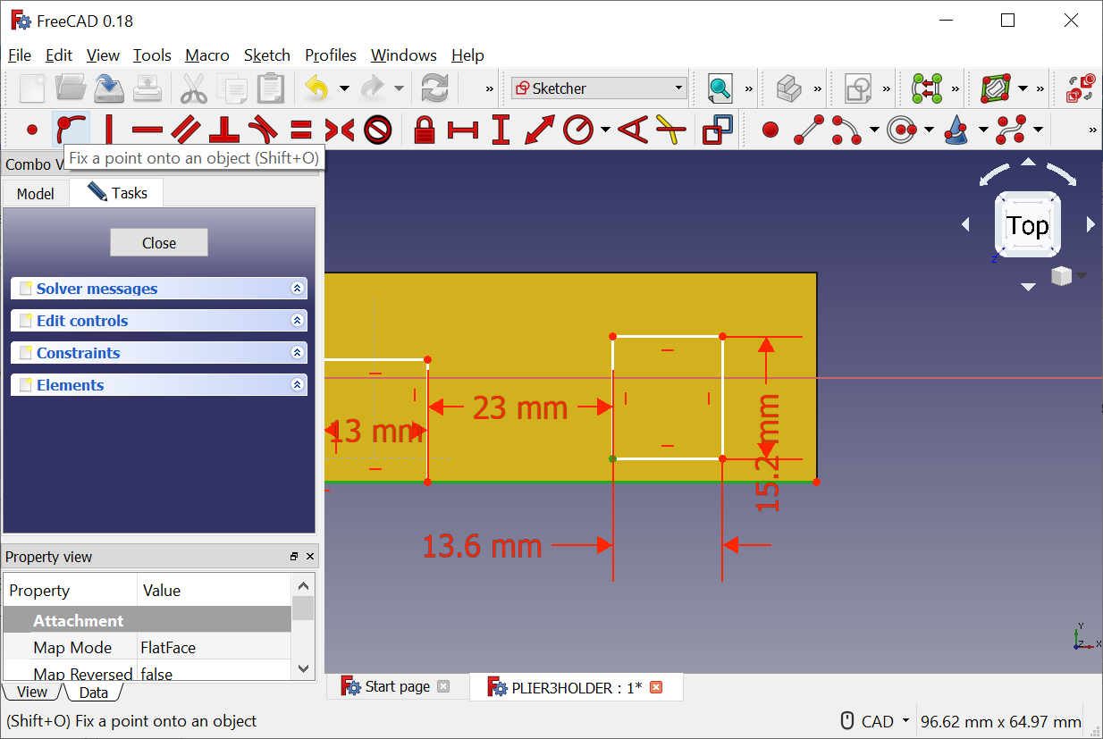
Add the individual tool holder pockets as cut extrusions in FreeCad, or edit existing.
The sketch workbench is a bit different from other similar software and it’s often necessary to apply additional coincident point constraints after drawing a sketch. Push the spacebar after selecting a hidden object in the tree to show it.
Switch to the Path Workbench
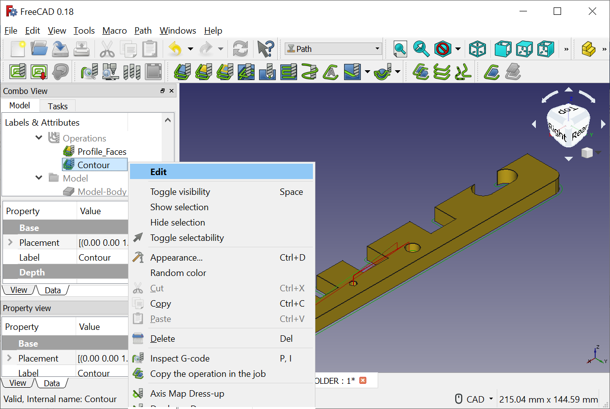
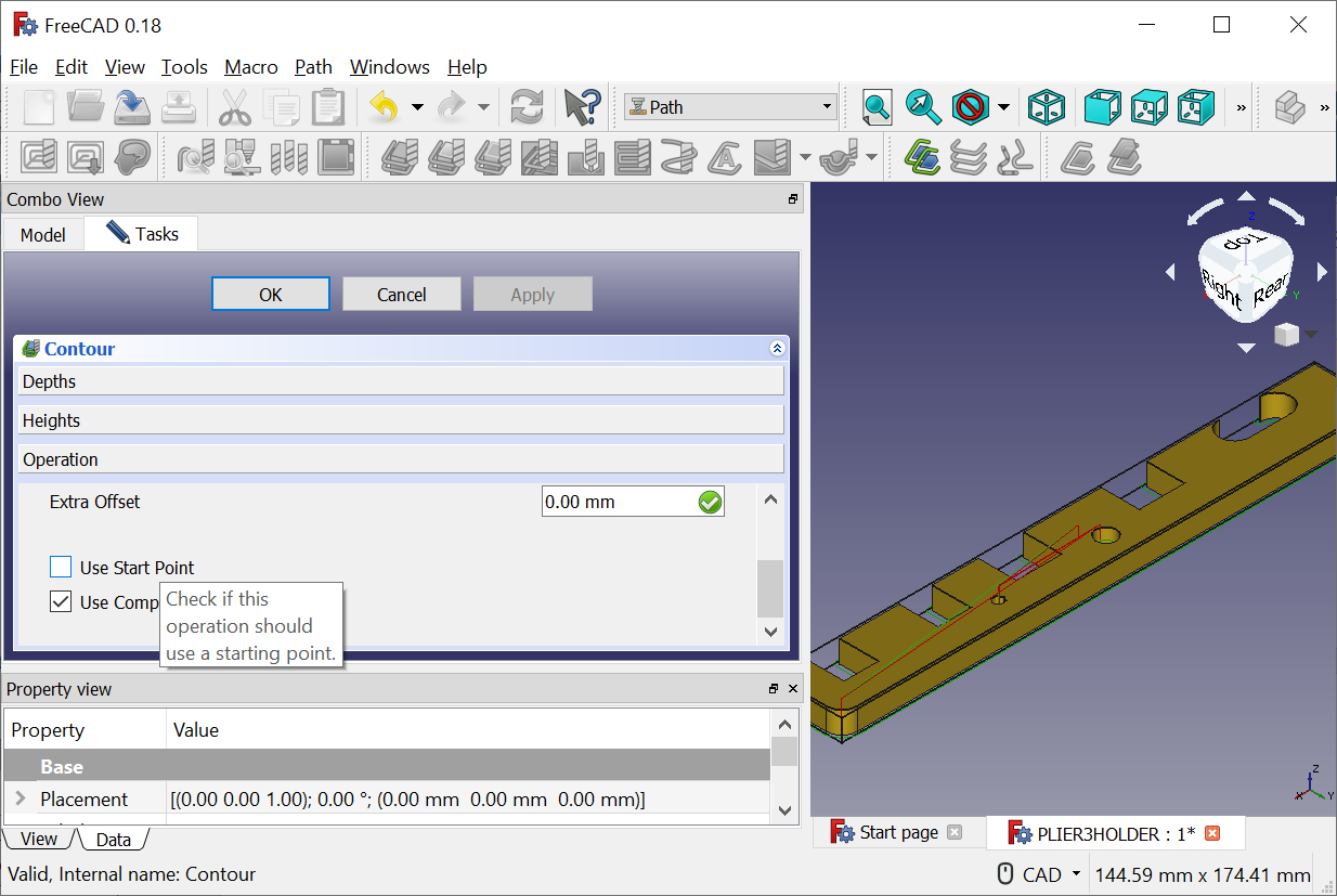
If the extruded cuts are connected to the outside of the part, it’s possible to simply edit the outer Contour job and rebuild by checking Use Start Point, click Apply, then Unchecking Use Start Point.
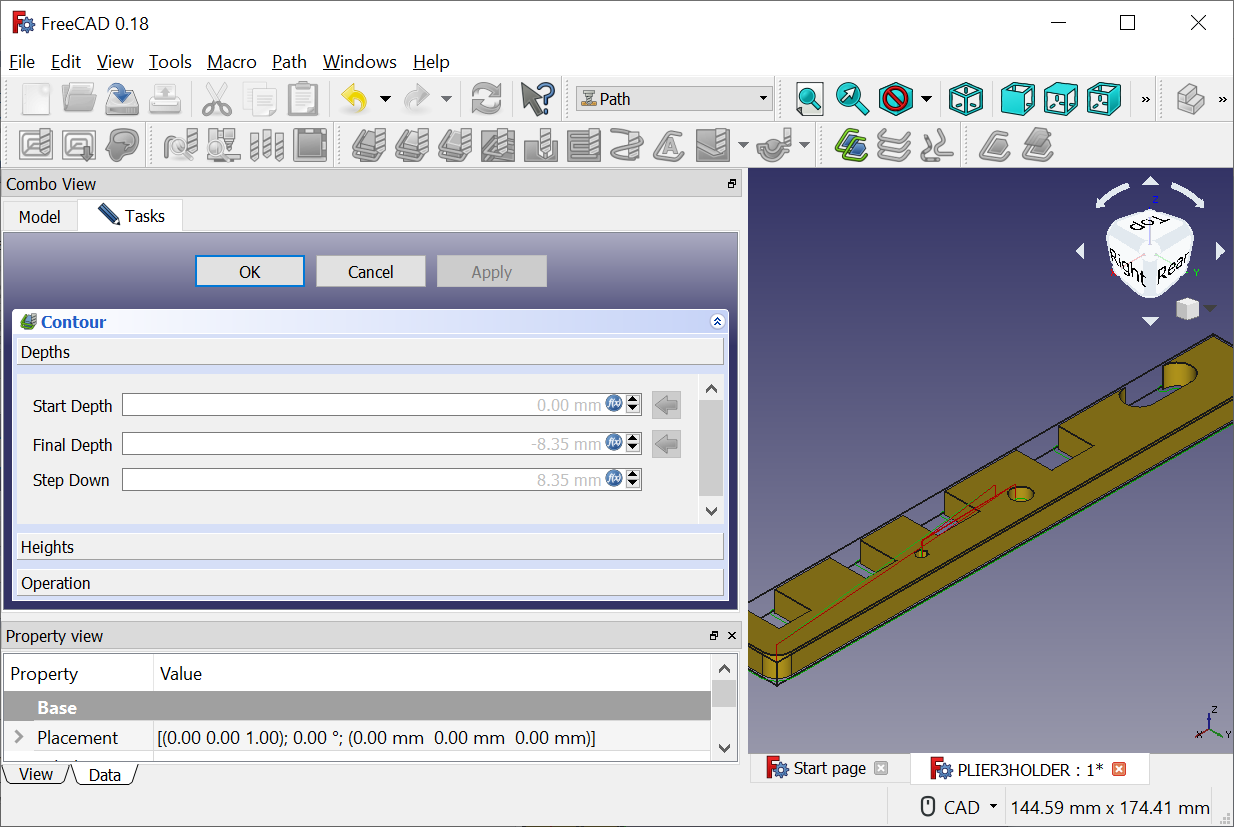
This project assumes the top of the material is 0 and any cuts into the material are -8.35mm. The step down is also 8.35mm, but may need to be reduced if you are cutting a harder material. Vinyl tile seems to have no issues cutting in one pass.
If you have any internal holes, the Profile Faces works well. You hold down the keyboard Ctrl key, then click all the vertical faces you want cut out. Also be sure the Contour operation is last, as this will cut out the part and remove it from the clamped piece.
Click the Job in the tree
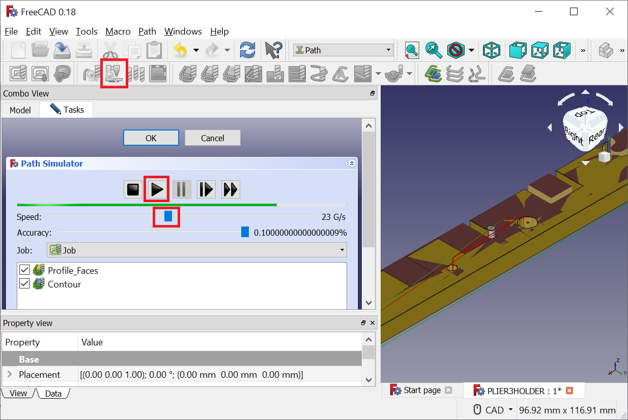
In the Path Menu select CAM Simulator, reduce the speed, and press the Play (Triangle) button to run the Simulation. If there is something wrong, the tool will usually just hang over the spot, and not do anything. This is usually some error in setting up the operation, or requires FreeCad to be restarted. Be prepared for frustration.
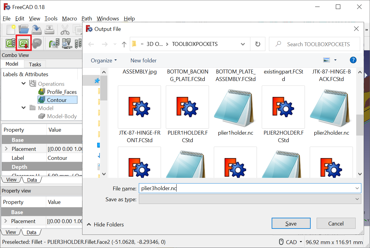
Once the Simulation works you can switch over to Post Process the selected Job, then it will prompt for a output gcode file again, and click Save.
Downloads
Open the Gcode Sender, Verify the Work Envelope and Cut
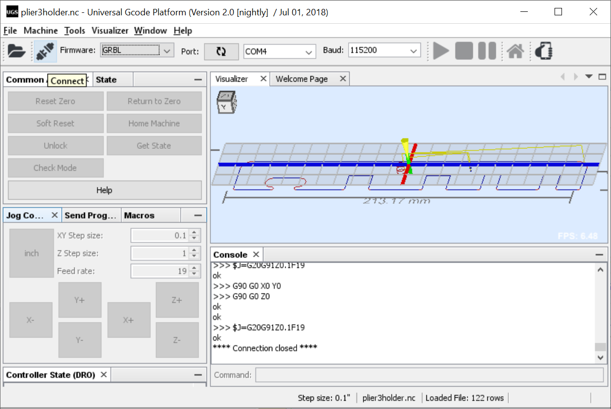
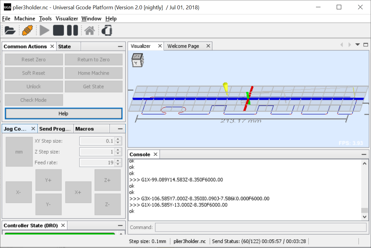
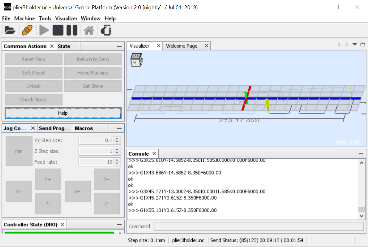
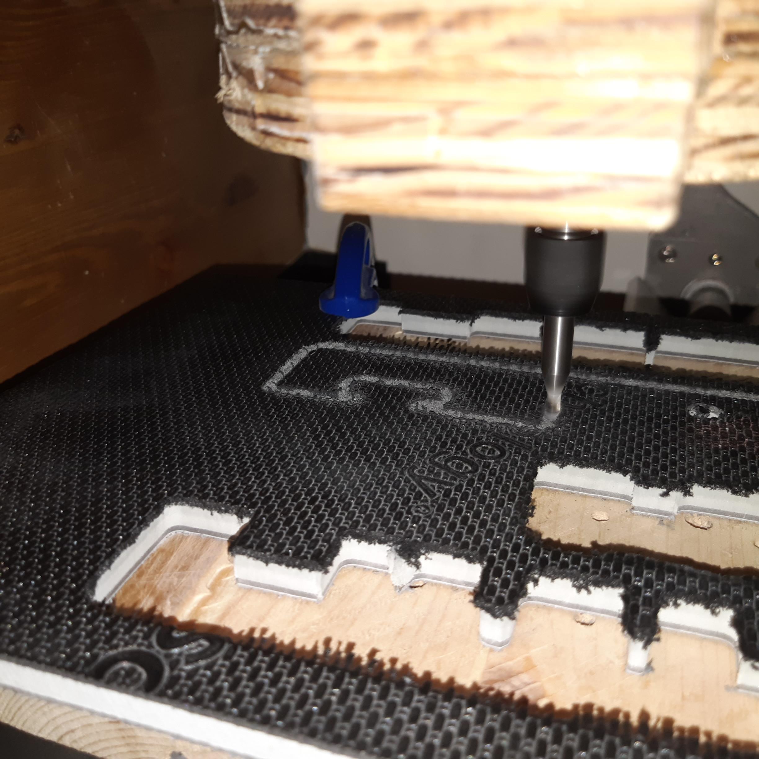
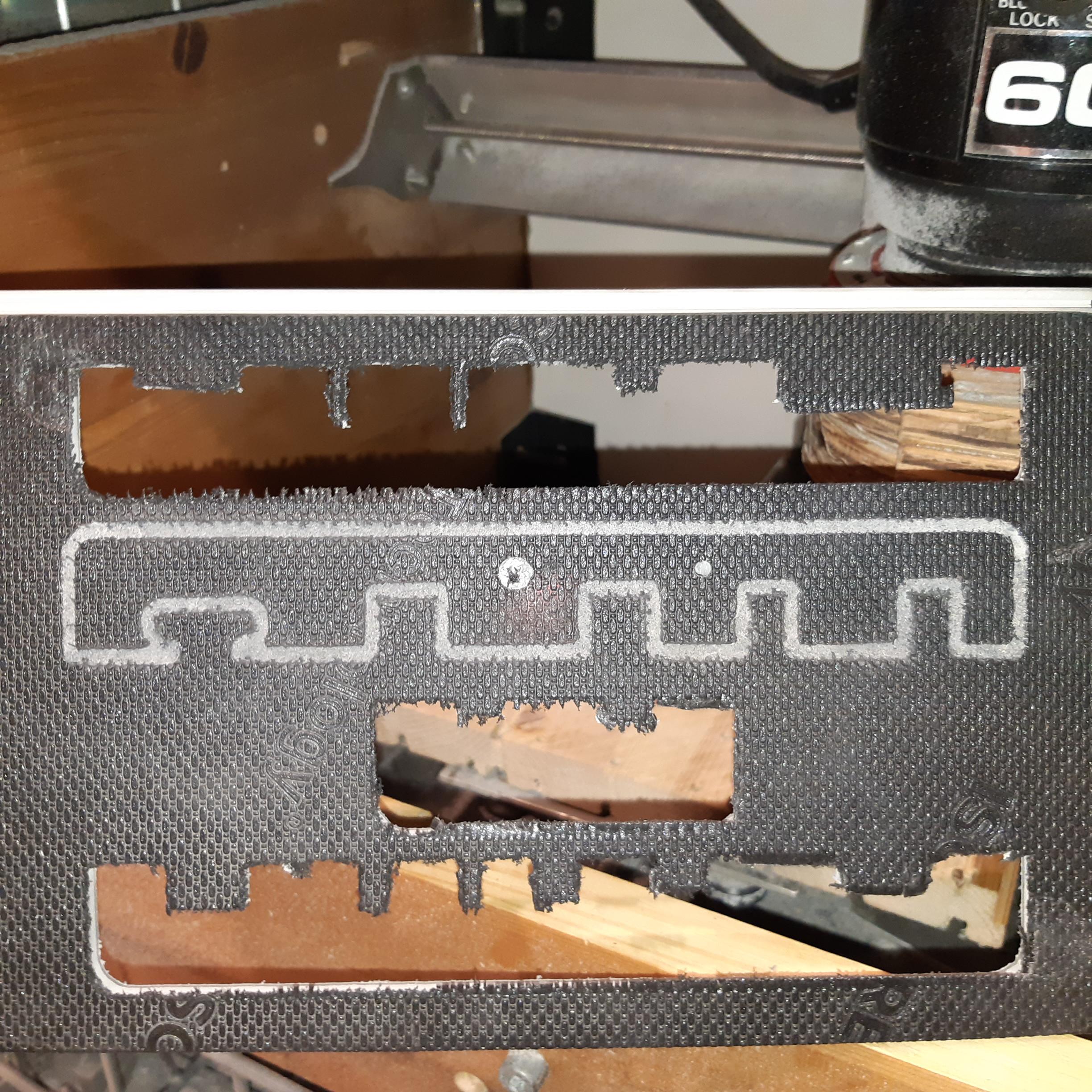
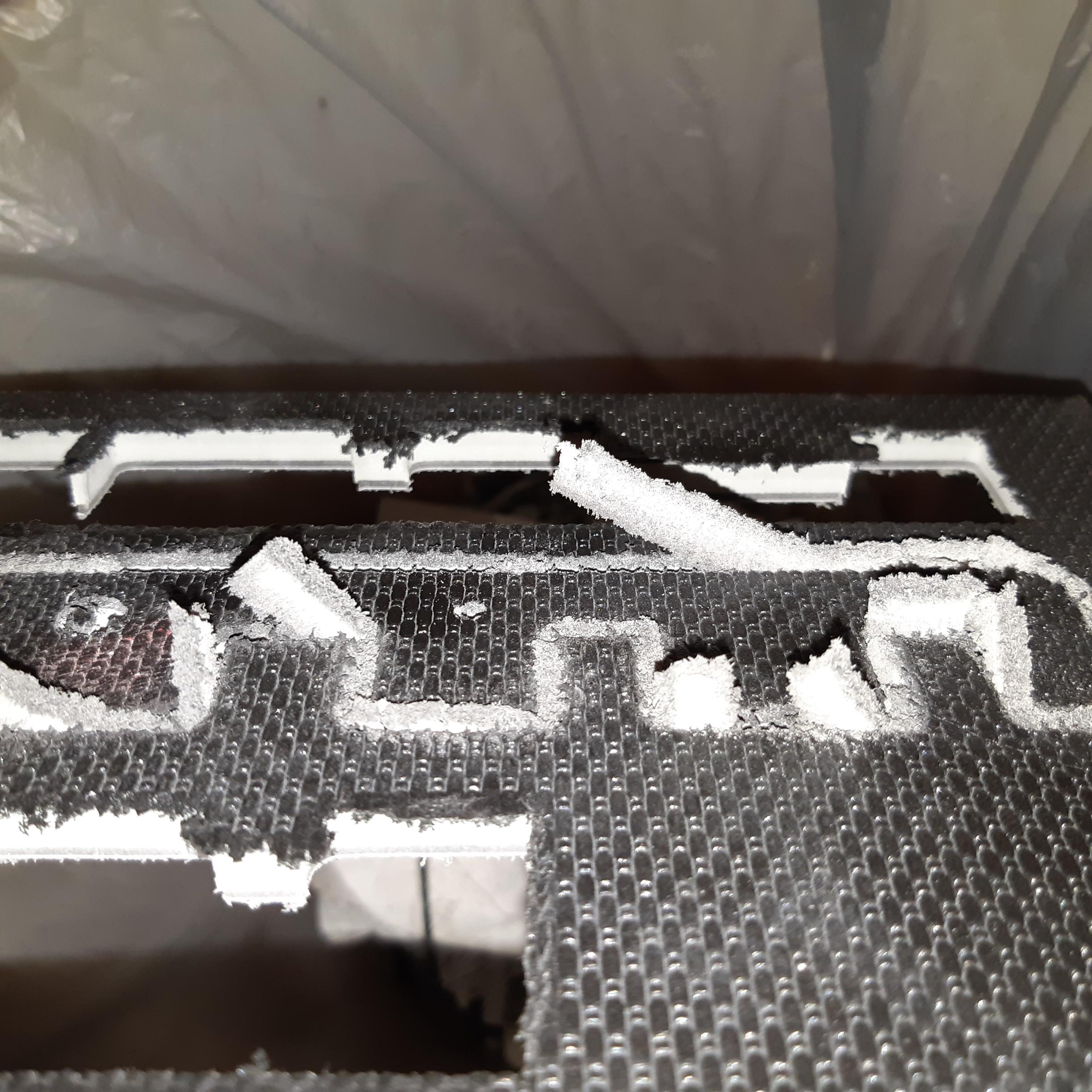
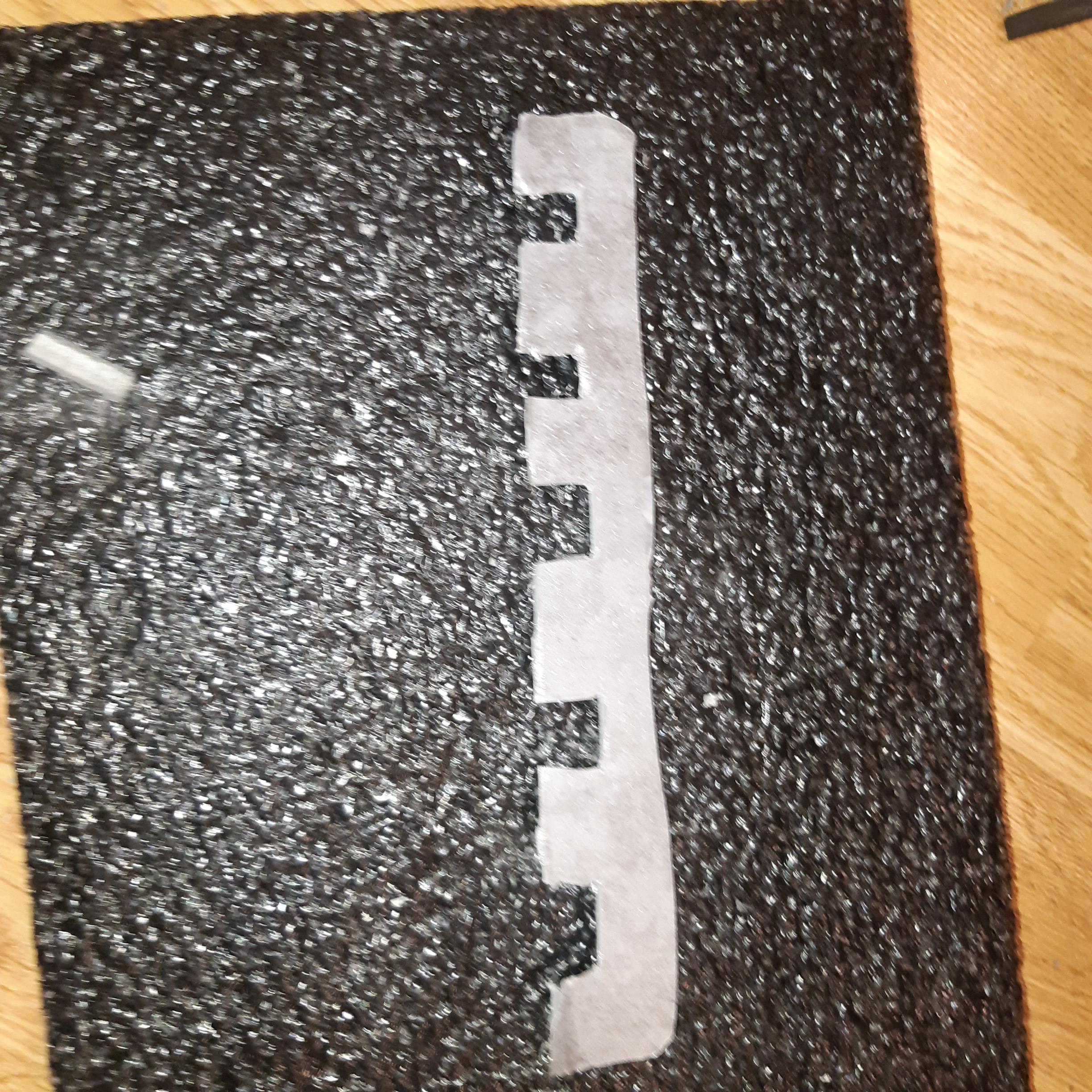
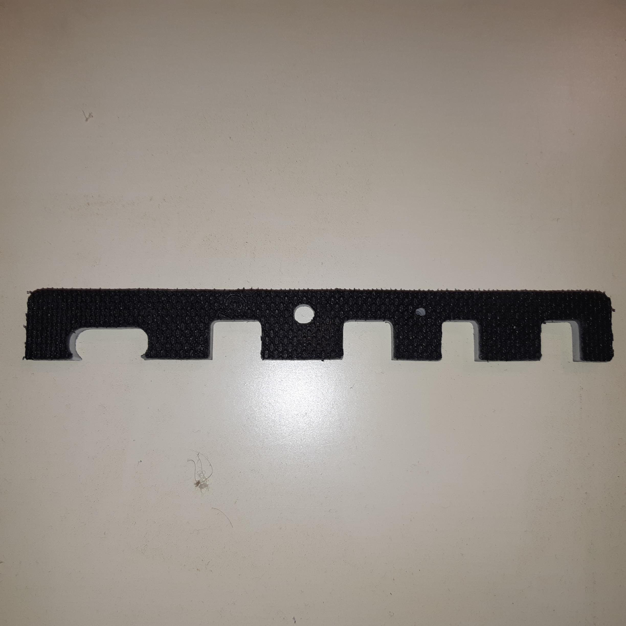
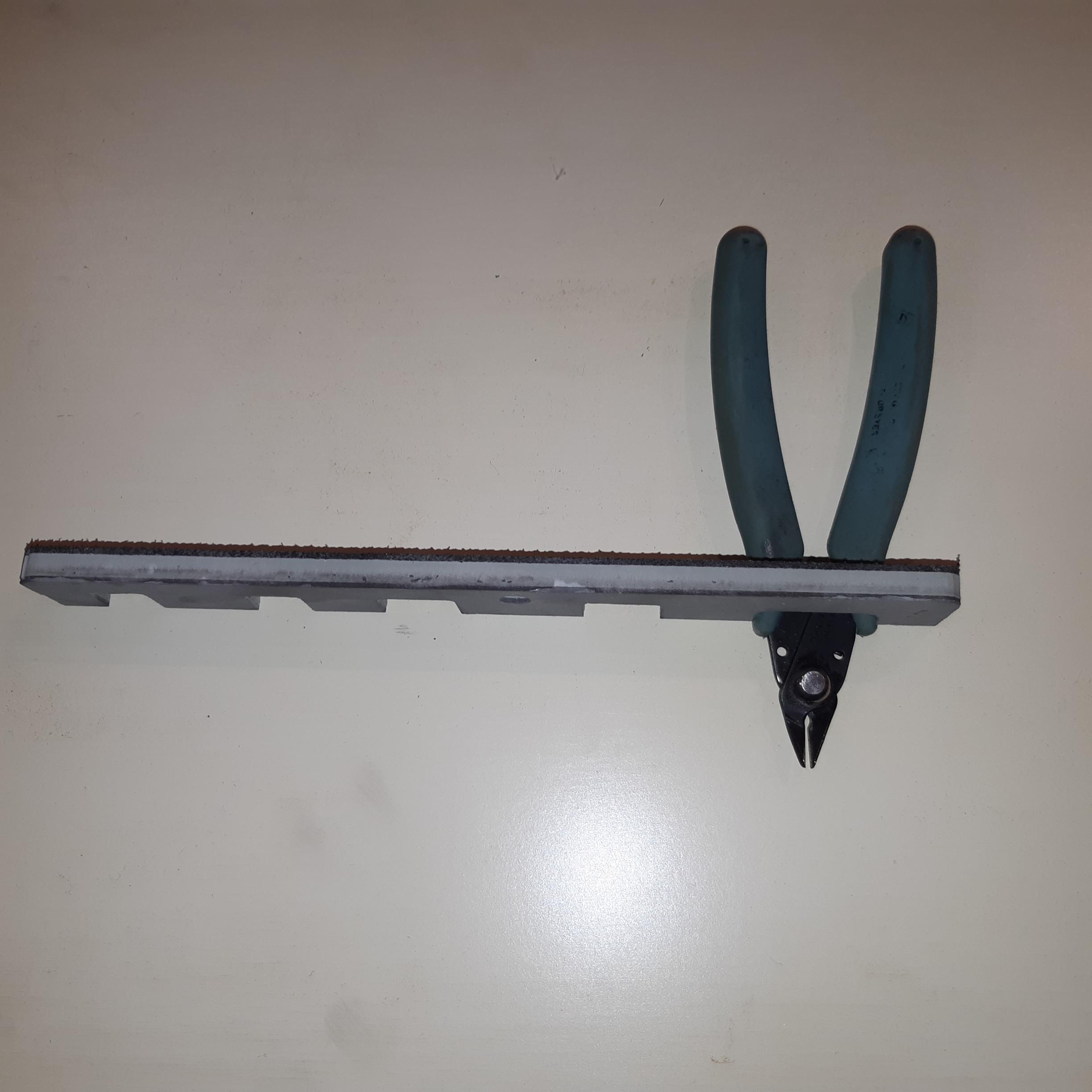
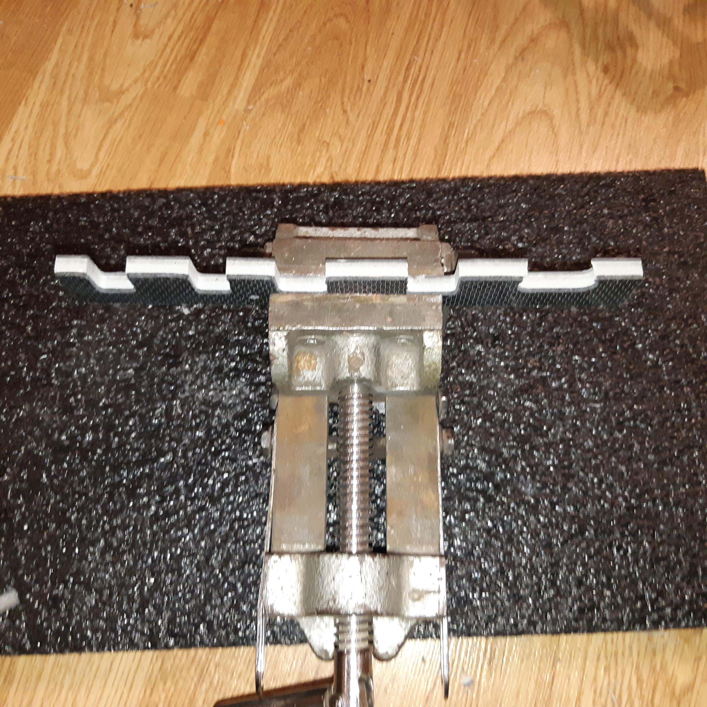
Launch Universal G-Code Sender, plug in and turn on your CNC,
Click Connect.
Click Open and find your gcode file.
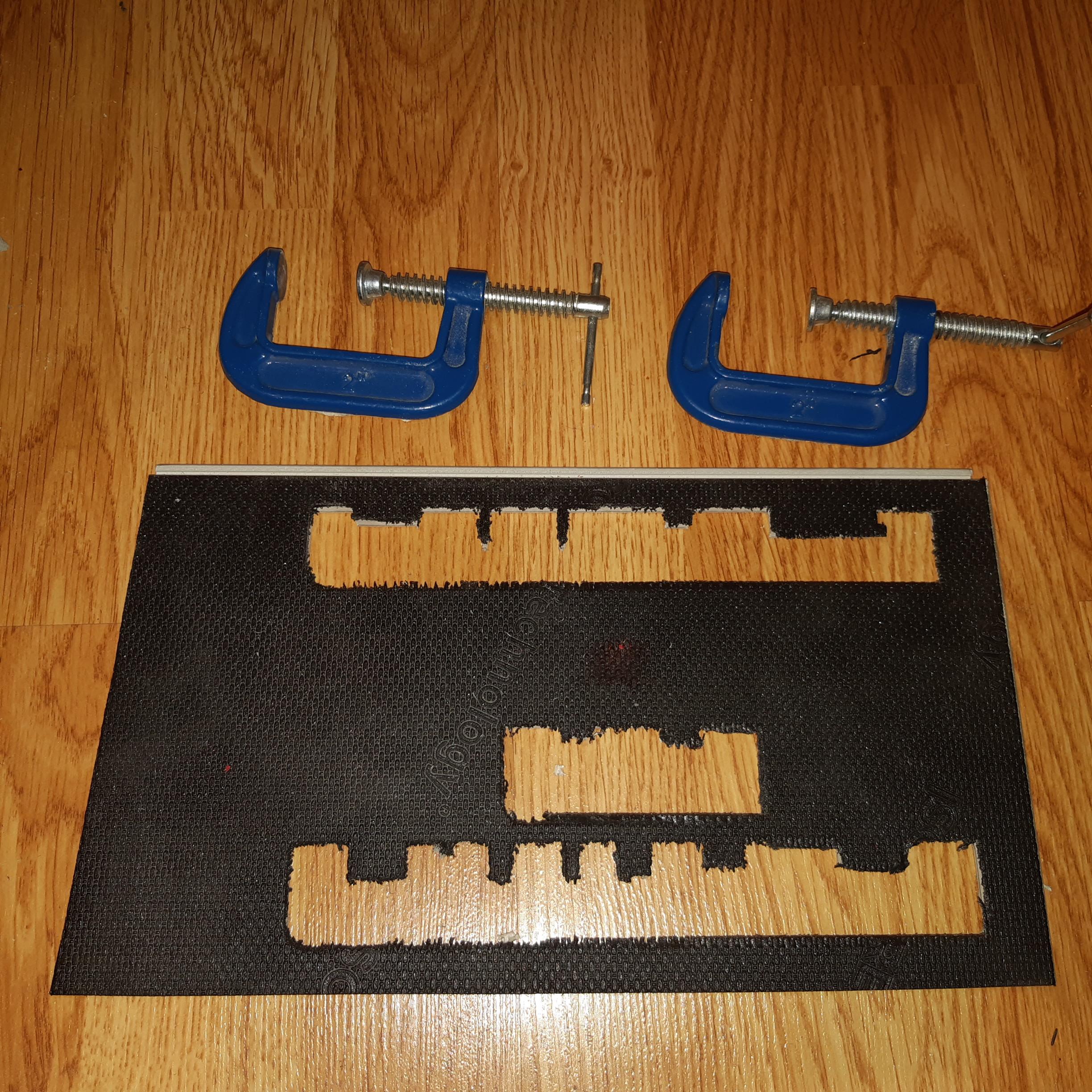
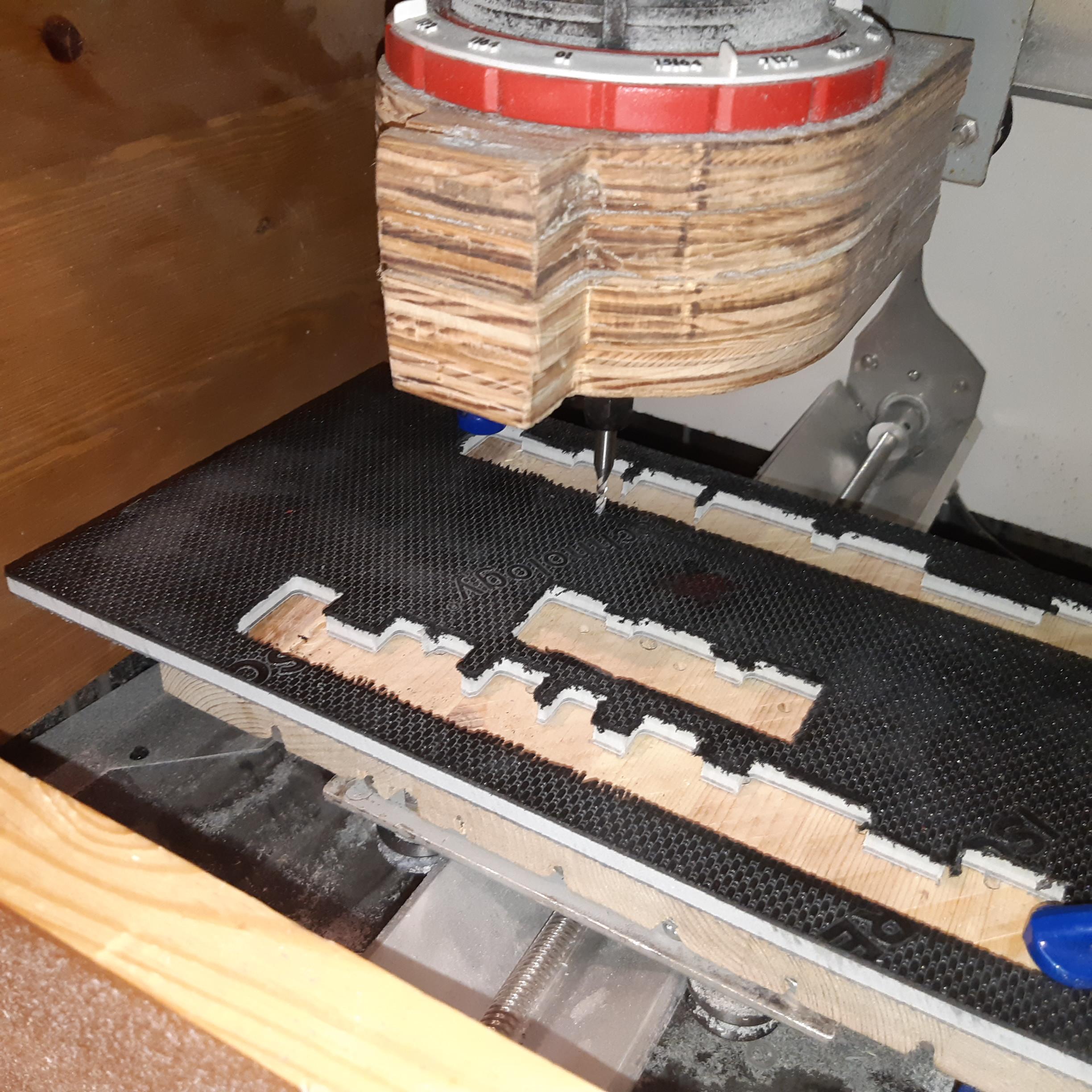
Clamp down cutting stock, ensure the clamps do not obstruct the spindle.
Ensure the cutting tool diameter is the same as defined in FreeCad
Jog the cutting tip above the center of the stock, and try to make efficient use of the material. Click reset Zero, this will define a new center position
If necessary, it’s possible to do a dry run if the cutting tip is much higher than the tool pluge.
Once confident with the cut envelope, it’s possible to Return to Zero, then jog lower the tool until it touches the piece. If you’re not sure the endmill has made contact, put a paper under it, and keep moving the paper until each 0.1mm jog finally results in the paper being stuck. Click Reset Zero.
Start the Spindle, and Send the Job (Play Button)
Verify the job completes successfully, low cost CNC systems need constant supervision. Cutting too much material in one pass can result in broken endmills or too much heat causing the endmill to plunge too deep.
Repeat the process for all the other tool holder shelves.
Drill Pilot Holes, Mount the Shelves and Assemble the Hinge
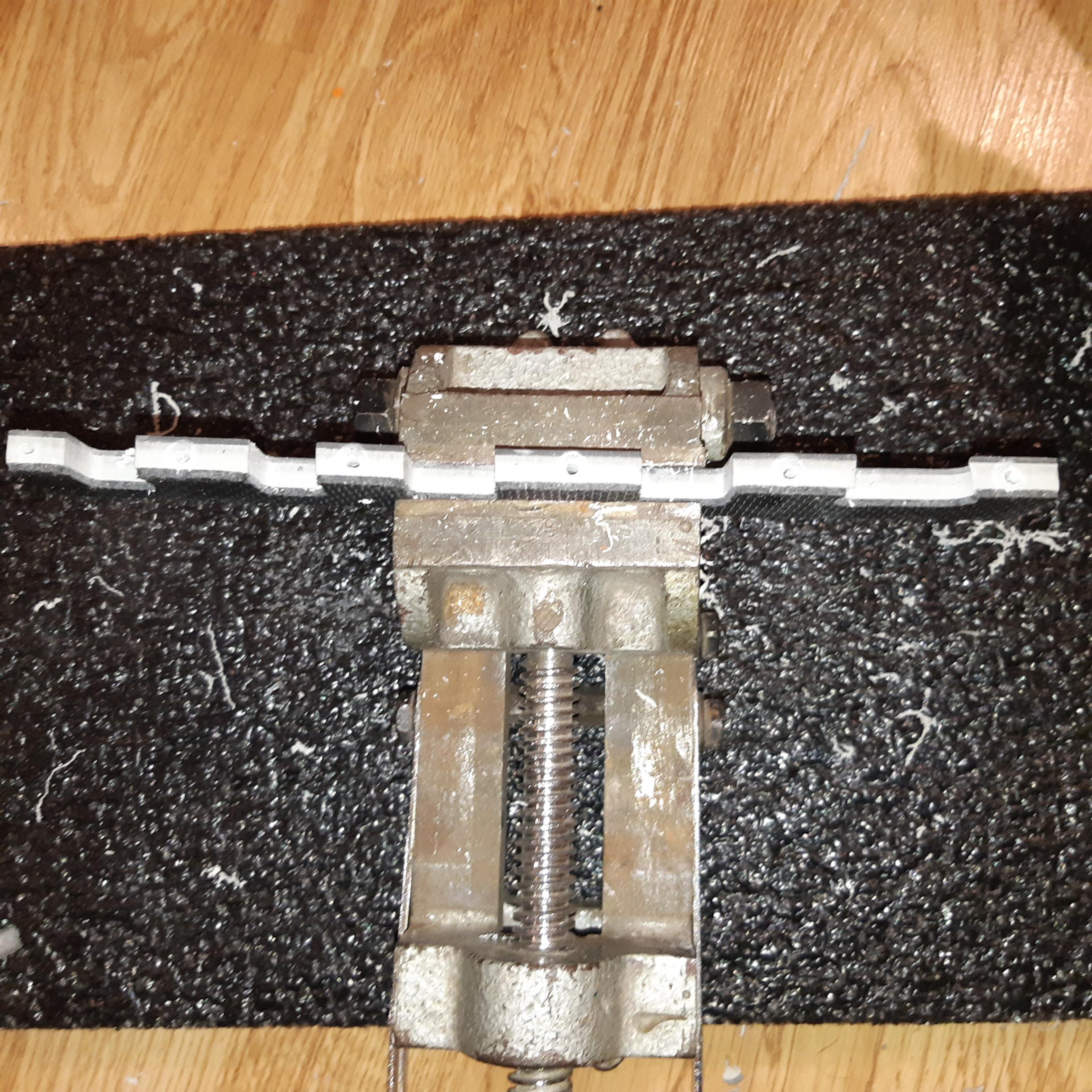
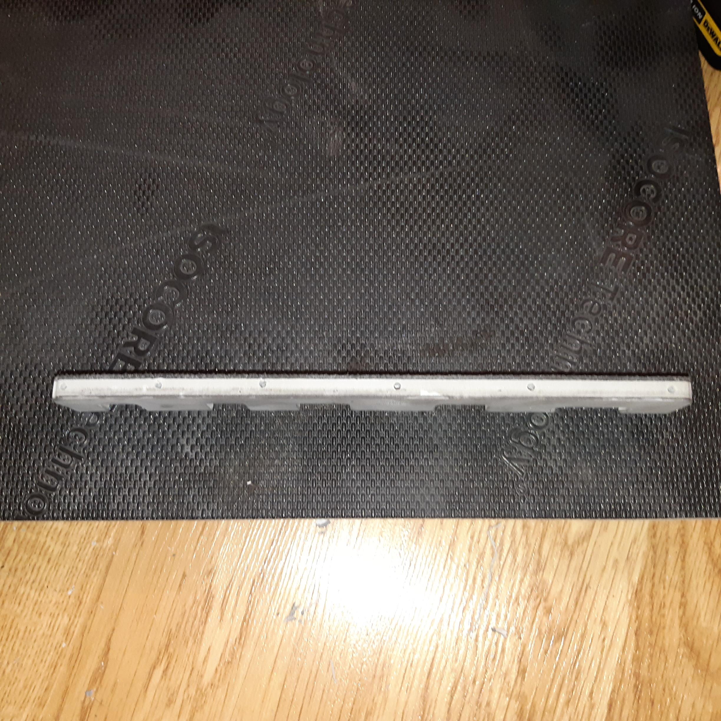
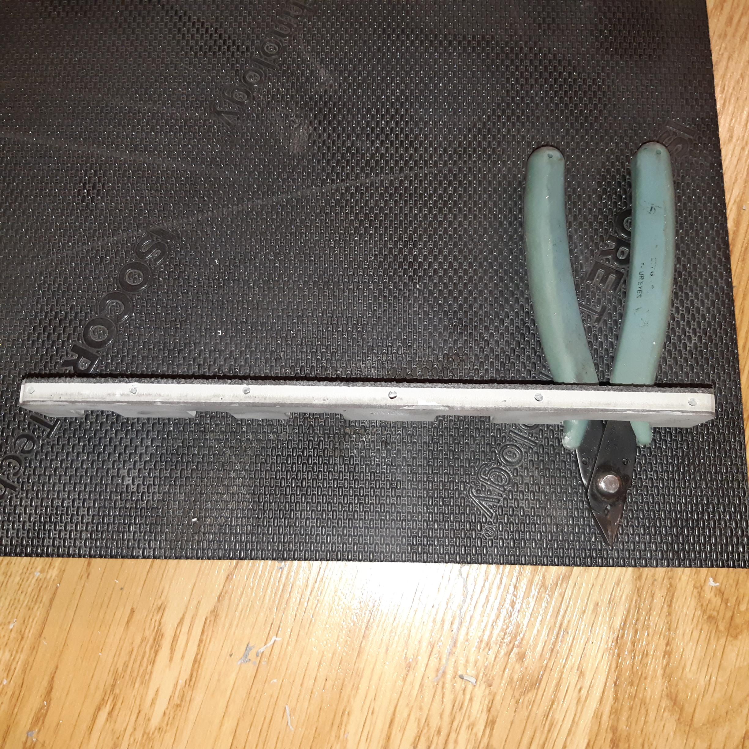
Once all the shelves are complete arrange them with the
tools they will be holding to ensure a good fit.
It may be necessary to file down some of the pockets if they are too small.
The tool shelves will be screwed on using thin metal plastic screws, or wood screws, and require pilot holes. Drill the pilot holes into the piece. Try a test piece to ensure the pilot holes are large enough to fit the screw tightly and that cracks don’t occur.
It’s difficult to perfectly measure the shelf locations, you can roughly measure, then eyeball the level, and clamp down the shelf. Proceed to drill through the shelf into the backer board.
Screw in from the back, ensure no gaps form.
Repeat for the other shelves.
If using a hinge, screw it onto both backer boards and test fit with your toolbox.