Save Your Life With the Building Collapse Monitor
by Electric boy in Circuits > Arduino
2138 Views, 7 Favorites, 0 Comments
Save Your Life With the Building Collapse Monitor

Analyse concrete, metal, wood structures for bends and angles and alerts if they have deviated from the original position.
Introduction
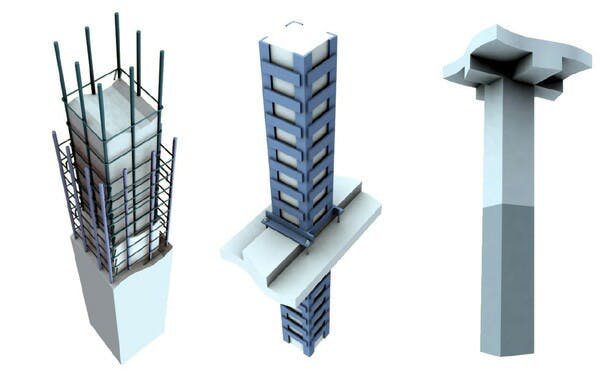
With the development of civil engineering field, we can identify a lot of constructions everywhere. Metal structures, Concrete beams, Multi-platform buildings are some of them. Further, most of us are used to stay in a building or home during most times of the day. But how can we assure that building is safe enough to stay? What if there’s a small crack or over-inclined beam in your building? It would risk a hundreds of lives.
Earthquakes, Soil hardness, Tornadoes and many more things, could be factors for internal cracks and the deviation of the structures or beams from the neutral position. Most of the times we are not aware of the situation of the surrounding structures. Maybe the place everyday we walk in has cracked concrete beams and can collapse at anytime. But without knowing it we are freely going inside.
As a solution for this, we need a good method to monitor concrete, wood, metal beams of constructions where we cannot reach.
Solution
“Structure Analyzer” is a portable device which can be mounted on a concrete beam, metal structure, slabs etc. This device measures the angle and analyze bends where it’s mounted and send the data to mobile app through Bluetooth. This device uses an accelerometer/ Gyroscope to measure the angle in x,y,z planes and flex sensor to monitor the bends. All raw data are processed and information is sent to the mobile app.
Circuit
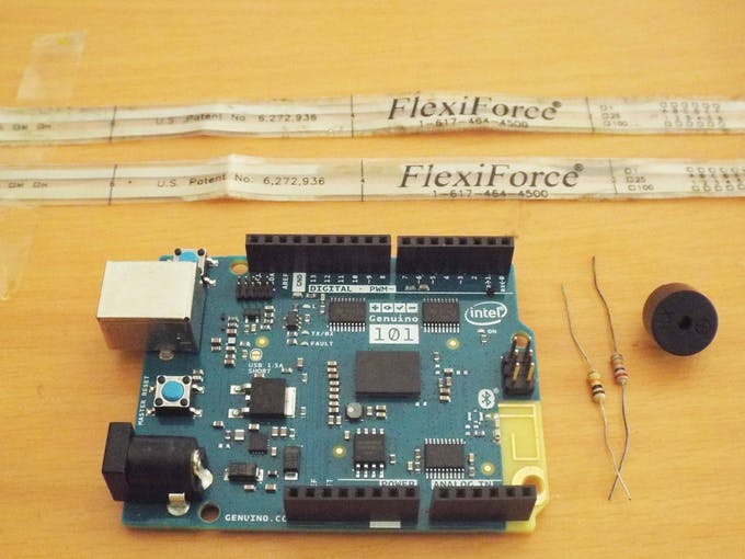

Collect the following components.
- Arduino 101 Board
- 2 X Flex sensors
- 2 X 10k Resistors
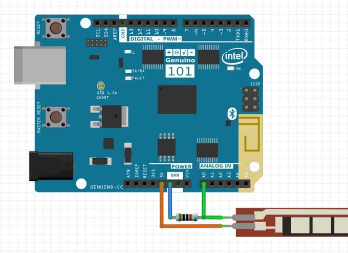
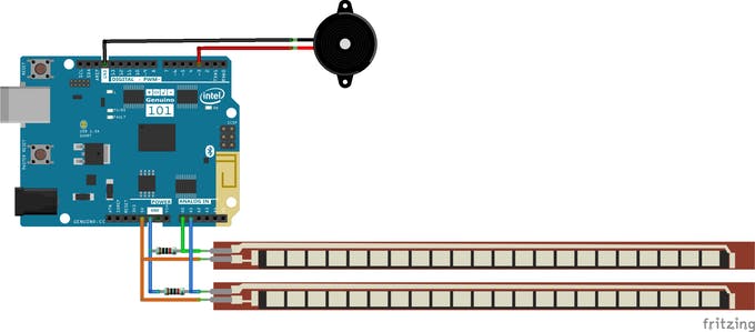
To reduce the number of components Arduino 101 board is used here as it contains an accelerometer and a BLE module. Flex sensors are used to measure the amount of bending as it changes it's resistance when bending. The circuit is a very small one as only 2 resistors and 2 flex sensors needed to be connected. Following diagram shows how to connect a flex sensor to the Arduino board.
One pin of the resistor is connected to the A0 pin of the Arduino board. Follow the same procedure to connect the second flex sensor. Use A1 pin to connect the resistor.
Connect the buzzer directly to the D3 pin and Gnd pin.
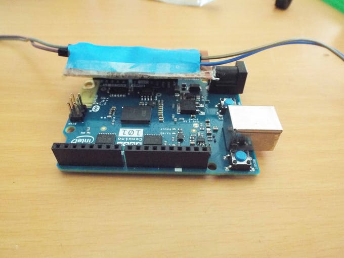
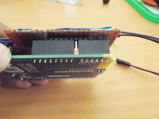
Finishing the Device
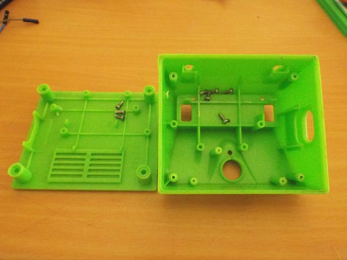
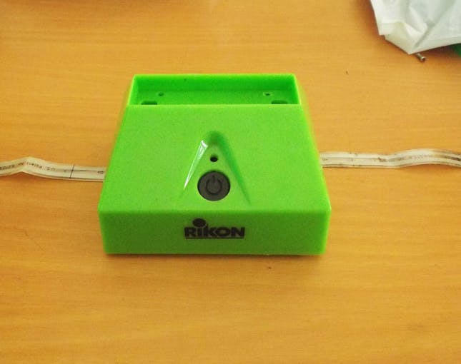
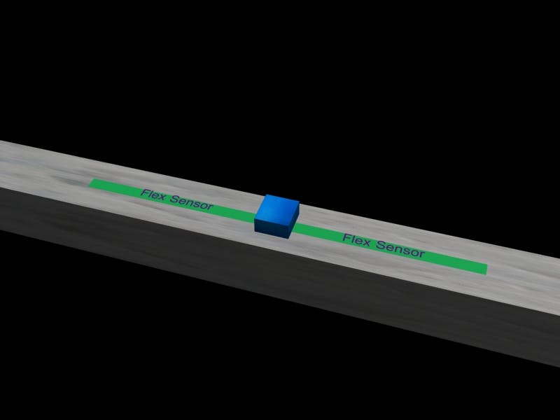
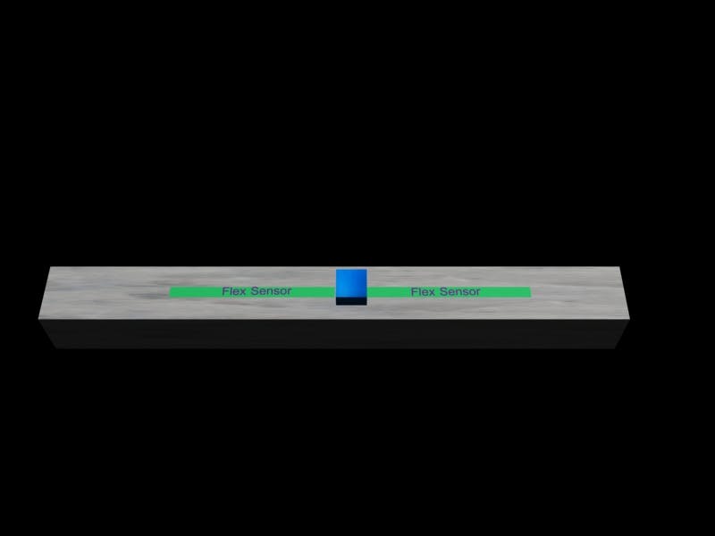
After making the circuit, it has to be fixed inside an enclosure. According to the above 3D model, 2 flex sensors have to be placed at the opposite side of the enclosure. Make space for the USB port to program the board and supply the power. As this device is needed to be used for a long period, the best method to supply power is using a fixed power pack.
Mobile App
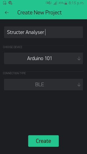

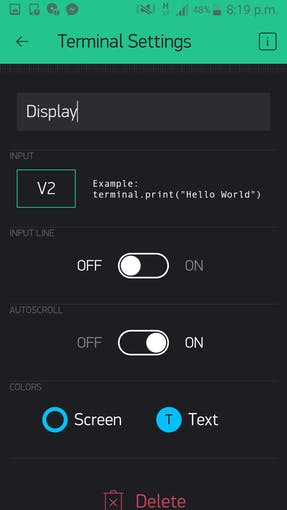
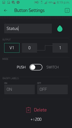
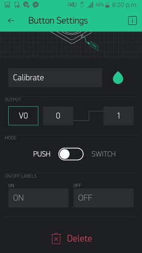
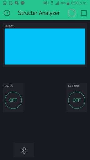
Download and install Blynk from the Android Play Store. Start a new project for Arduino 101. Select the communication method as BLE. Add 1 terminal, 2 buttons and BLE to the interface. Following images show you how to make the interface.
Blynk Code Files
After making the interface on Blynk you will receive an authorization code. Enter that code at the following place.
#include
#include char auth[] = "**************"; //Blynk Authorization Code
WidgetTerminal terminal(V2);
BLEPeripheral blePeripheral;
In the calibration process, current sensor readings are saved in the EEPROM.
values();
EEPROM.write(0,flx1);
EEPROM.write(1,flx2);
EEPROM.write(2,x);
EEPROM.write(3,y);
EEPROM.write(4,z);
terminal.print("Calibration Succesful");
After calibrating, the device will compare the deviation with the threshold values and beeps the buzzer if they exceed the value.
values();
if(abs(flex1-m_flx1)>10 or abs(flex2-m_flx2)>10){
terminal.println("Over Bend");
tone(buzzer, 1000);
}
if(abs(x-m_x)>15 or abs(y-m_y)>15 or abs(z-m_z)>15){
terminal.println("Over Inclined");
tone(buzzer, 1000);
}
Functionality

Stick the device to on the structure needed to be monitored. Stick the 2 flex sensors as well. Supply power to the board using the USB cable.
Open the Blynk interface. Connect with the device by touching the Bluetooth icon. Press the calibration button. After calibrating the terminal will show a message as "Successfully Calibrated." Reset the device. Now it will monitor the structure and notifies you through the buzzer if it deviates of deforms. You can check the angle and bend values at any time by pressing the Status button. This might looks like a small device. But its' uses are priceless. Sometimes we forget to check the condition of our home, office etc, with our busy schedules. But if there is a small problem, it might end like as the figure above.
But with this device, a hundreds of lives can be saved by informing the small yet dangerous problems in constructions.
Arduino101 Code File
#define BLYNK_PRINT Serial
#define flex1 A0
#define flex2 A1 //Define flex sensor and buzzer pins
#define buzzer 3
#include "CurieIMU.h"
#include "BlynkSimpleCurieBLE.h"
#include "CurieBLE.h"
#include "Wire.h"
#include "EEPROM.h"
#include "SPI.h"
char auth[] = "**************"; //Blynk Authorization Code
WidgetTerminal terminal(V2);
BLEPeripheral blePeripheral;
int m_flx1,m_flx2,m_x,m_y,m_z; //values saved in memory
int flx1, flx2,x,y,z; //Current readings
void values(){
for(int i=0;i<100;i++){
flx1 = analogRead(flex1); //Get raw readings from sensors
flx2 = analogRead(flex2);
x = CurieIMU.readAccelerometer(X_AXIS)/100;
y = CurieIMU.readAccelerometer(Y_AXIS)/100;
z = CurieIMU.readAccelerometer(Z_AXIS)/100;
delay(2);
}
flx1=flx1/100;
flx2=flx2/100;
x = x/100; //Get the average values of the readings
y = y/100;
z = z/100;
}
void setup(){
//pinMode(3,OUTPUT);
pinMode(flex1,INPUT);
pinMode(flex2,INPUT); //Setting the sensor pin modes
Serial.begin(9600);
blePeripheral.setLocalName("Arduino101Blynk");
blePeripheral.setDeviceName("Arduino101Blynk");
blePeripheral.setAppearance(384);
Blynk.begin(auth, blePeripheral);
blePeripheral.begin();
m_flx1 = EEPROM.read(0);
m_flx2 = EEPROM.read(1);
m_x = EEPROM.read(2); //Read pre saved sensor values from EEPROM
m_y = EEPROM.read(3);
m_z = EEPROM.read(4);
}
void loop(){
Blynk.run();
blePeripheral.poll();
values();
if(abs(flex1-m_flx1)>10 or abs(flex2-m_flx2)>10){
terminal.println("Over Bend");
tone(buzzer, 1000);
}
if(abs(x-m_x)>15 or abs(y-m_y)>15 or abs(z-m_z)>15){
terminal.println("Over Inclined");
tone(buzzer, 1000);
}
tone(buzzer, 0);
}
/*VO indicates the calibration mode. In this mode the values of sensors
* are saved in the EEPROM
*/
BLYNK_WRITE(V0){
int pinValue = param.asInt();
if (pinValue == 1){
values();
EEPROM.write(0,flx1);
EEPROM.write(1,flx2);
EEPROM.write(2,x);
EEPROM.write(3,y);
EEPROM.write(4,z);
terminal.print("Calibration Succesful");
}
}
/*We can request current deviation values
* by pressing the button V1
*/
BLYNK_WRITE(V1){
int pinValue = param.asInt();
if (pinValue == 1){
values();
terminal.print("X angle deviation- ");
terminal.print(abs(x-m_x));
terminal.println();
terminal.print("Y angle deviation- ");
terminal.print(abs(y-m_y));
terminal.println();
terminal.print("Z angle deviation- ");
terminal.print(abs(z-m_z));
terminal.println();
terminal.print("Flex 1 deviation- ");
terminal.print(abs(flx1-m_flx1));
terminal.println();
terminal.print("Flex 2 deviation- ");
terminal.print(abs(flx2-m_flx2));
terminal.println();
}
}
BLYNK_WRITE(V2){
}