SafeGuard360: Precision PPE Detection System for Enhanced Workplace Safety
by Farah Yakoubi in Circuits > Raspberry Pi
317 Views, 3 Favorites, 0 Comments
SafeGuard360: Precision PPE Detection System for Enhanced Workplace Safety
Hi, I'm Farah Yakoubi, a first-year student in Creative Technology & AI at Howest University Kortrijk. For my project, I've developed an innovative system that leverages automated detection, computer vision, and machine learning technologies to enhance safety protocols in warehouse environments.
This system is designed to ensure that staff members comply with safety regulations by wearing the necessary personal protective equipment (PPE) such as vests, helmets, and shoes. By automating the monitoring process, this project aims to improve workplace safety and create a more secure and efficient working environment.
When an employee stands at the PPE checkpoint, the system uses bounding boxes visible on the display to verify if they are wearing all required PPE. If the PPE is worn correctly, a green LED indicator will illuminate, allowing them to proceed with work. If any item is missing, a red LED will light up and a buzzer will sound, preventing the employee from commencing work until they have all the necessary gear.
Join me in this Instructable guide as I walk you through the process of creating this safety-enhancing system for warehouses.
Downloads
Supplies
- Freenove Projects Kit for Raspberry Pi (FNK0054)
- Raspberry Pi 5 - 8GB - Starter Pack (2023)
- HD Webcam
- RGBLED Module (incl. in Projects Kit)
- Active Buzzer (incl. in Projects Kit)
Make a Roboflow Account
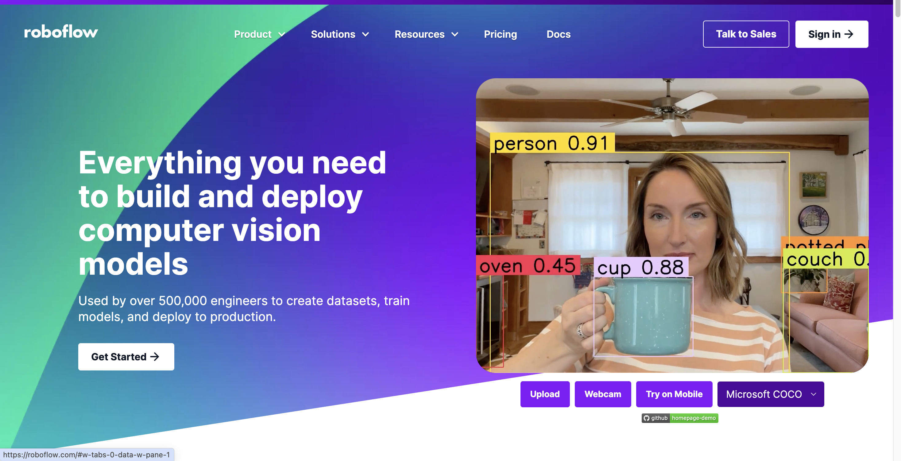
For this project, I utilized Roboflow, a platform tailored to support the development and deployment of computer vision models. Roboflow offers a comprehensive suite of tools that manage the entire lifecycle of computer vision projects, including data collection, annotation, augmentation, model training, deployment, and numerous other benefits. Within the platform, you can also select the type of computer vision task. In this case, object detection will be used.
Collect Data
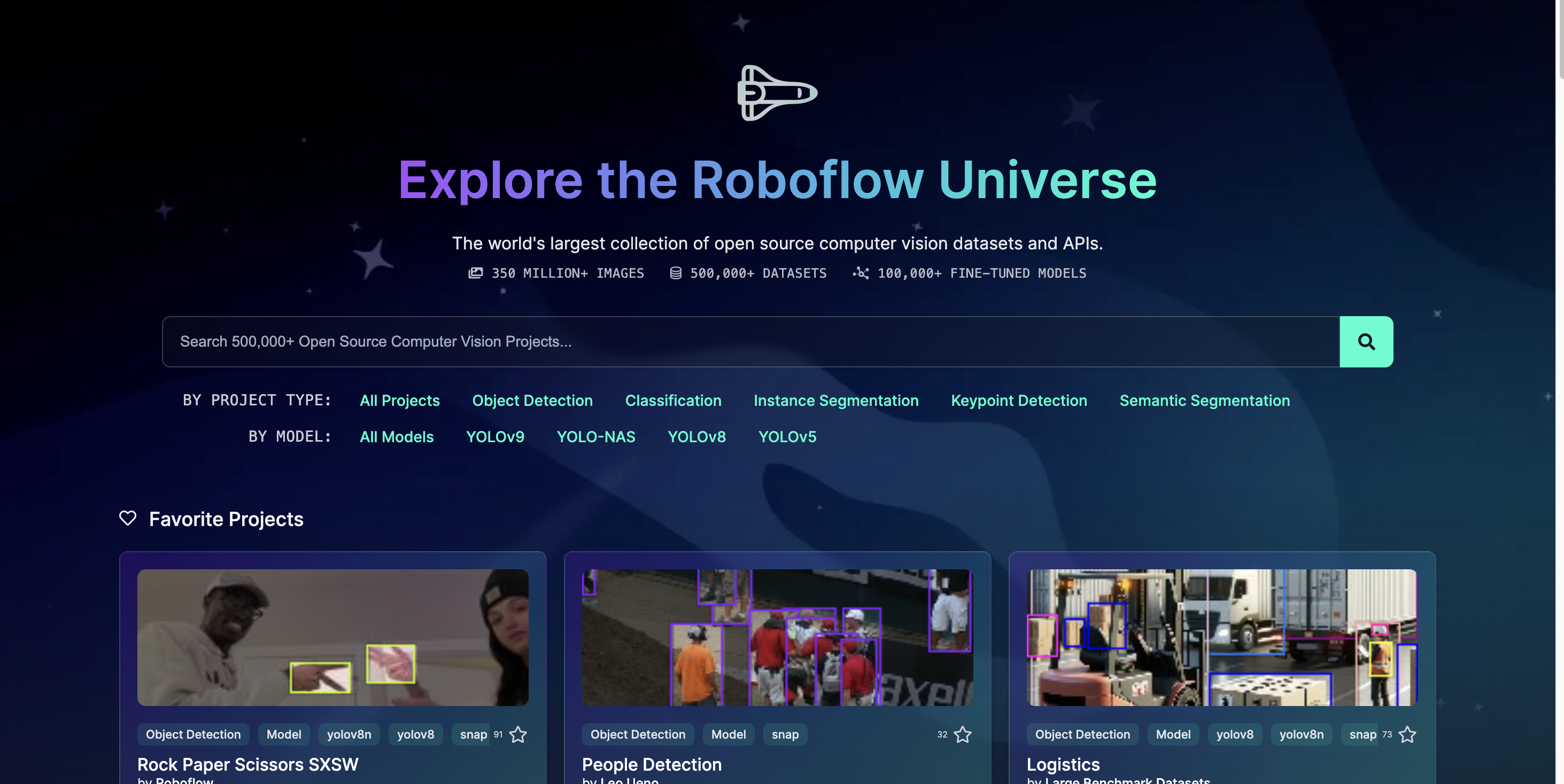
The initial phase of this project involves data collection. To develop an effective model, it's crucial to gather a substantial amount of data and ensure it is evenly distributed across the chosen classes. Additionally, incorporating unannotated data is important to prevent the model from consistently favoring certain elements.
There are various methods to collect data. Personally, I primarily used data from Roboflow Universe and performed independent searches. If you find data on Roboflow Universe, you can simply clone it into your project (with or without the classes). If additional data is needed, consider exploring Kaggle or Google Dataset.
Annotate Data
Once you've gathered enough data, it's time to annotate any unannotated data. Here's how to do it:
1. Go to "Upload Data."
2. Select your files.
3. Click on each picture individually and start annotating.
4. Once you've finished annotating, click "Save and Continue."
You now have an annotated dataset.
Before proceeding to the next step, ensure you click on the health check to verify that all classes are well balanced.
If these steps are unclear, please refer to this guide
Generate Version
Once you've completed annotating your data and are confident that your dataset is accurate and well balanced, you can proceed to generate the dataset. The process will be as follows:
- Click "Versions"
- Click "New Version"
- Start Preprocessing
- Click "Apply"
- Click "Continue"
- Start "Augmentation"
- Choose "Augmentation Options"
- Choose Maximum Version Size"
- Click "Create"
If these steps are unclear, please refer to this guide
Export Dataset to YoloV8 Format
After creating the dataset, you can export it and begin the real work: training your model.
There are several ways to do this, such as using Visual Studio Code or Google Colab. I personally chose Google Colab because it provides free GPU access, which allows for faster training. However, this is a personal preference. In this guide, I will demonstrate using Google Colab.
To export the dataset follow this guide.
Train the Model
Now that your model has been exported, the training process begins.
To train your model follow this guide.
Please note that the duration of the training may vary depending on the image size and quantity and amount of epochs.
Deploy the Model
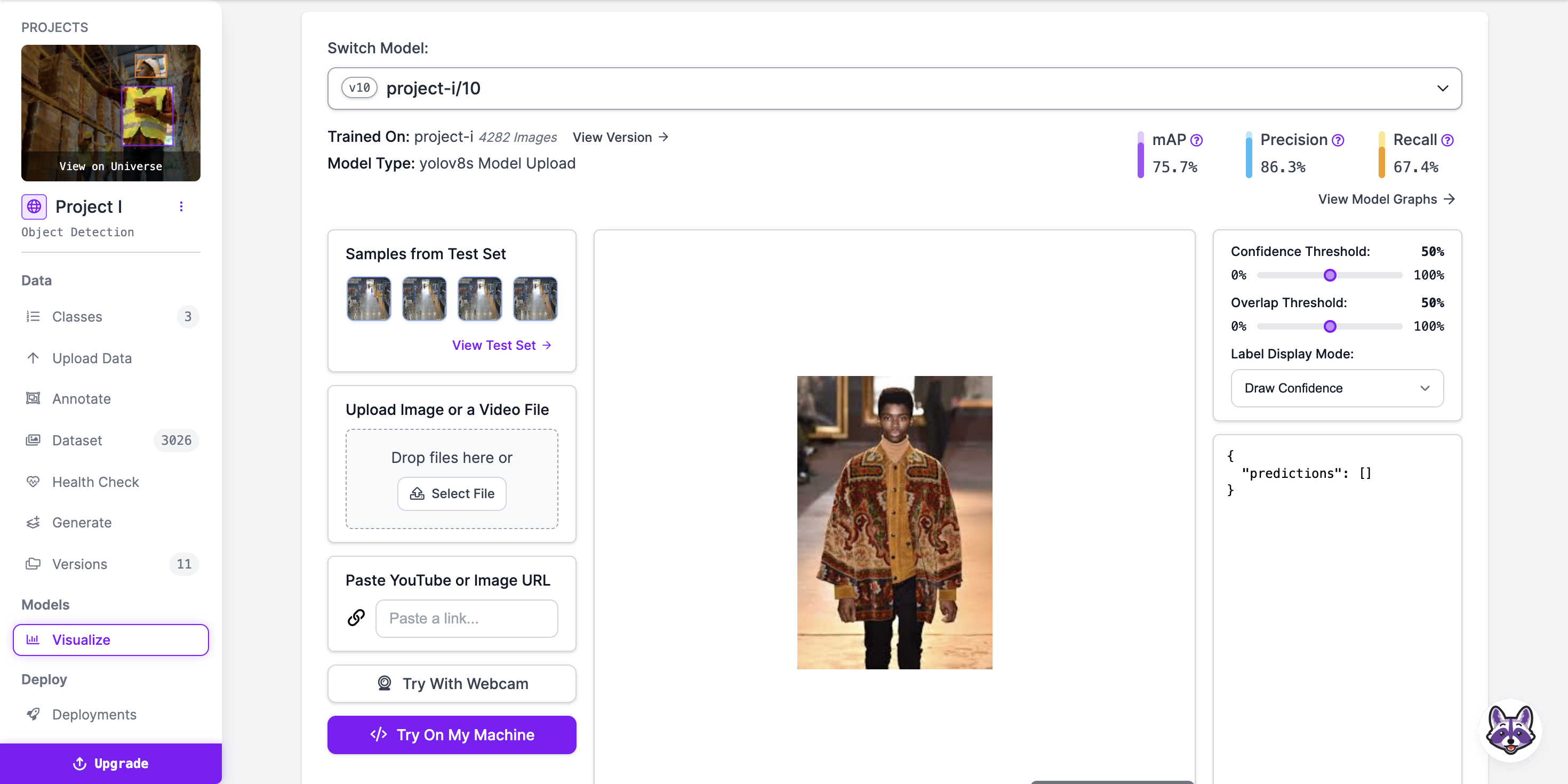
After training the model, utilize the following code to deploy it in Roboflow and assess its performance:
version.deploy("yolov8","runs/detect/train")
Executing this code will provide a link. Click on the link to be redirected back to Roboflow. Please be patient as it may take some time to load. Once loaded, click on "Visualize" to test the model and evaluate its performance.
Adjust the model extensively to maximize its performance, ensuring it accurately detects all PPE gear. Ensure the model only detects items when they are present on the screen, rather than attempting to detect every single frame.
Setting Up a Streamlit UI for PPE Detection
Here I will walk you through creating a simple user interface for a Personal Protective Equipment (PPE) detection system using Streamlit. The code provided allows users to adjust settings, view video input, and see detection results in real-time.
Step 1: Importing Necessary Libraries
First, you need to import the required libraries. Streamlit is used for the UI, while OpenCV (cv2) is used for handling video input. The ultralytics library is for loading the YOLO model, and tempfile helps with handling uploaded files.
import streamlit as st
import cv2
from ultralytics import YOLO
import tempfile
Step 2: Setting Up the Page Configuration
We use st.set_page_config to set up the page title and layout of the Streamlit application.
st.set_page_config(page_title="PPE detection in Warehouse", layout="wide")
st.title("PPE detection in Warehouse")
This sets the title of the page to "PPE detection in Warehouse" and configures the layout to be wide, providing more space for displaying video and results.
Step 3: Creating a Confidence Threshold Slider
A slider is added to the sidebar to allow users to adjust the confidence threshold for detections. This threshold determines how confident the model needs to be before it considers a detection valid.
conf_threshold = st.slider("Confidence Threshold", min_value=0.0, max_value=1.0, value=0.5)
This slider ranges from 0.0 to 1.0, with a default value of 0.5.
Step 4: Adding Placeholders for Image and Results
Placeholders are used to dynamically update the displayed image and results during the video processing.
image_placeholder = st.empty()
results_placeholder = st.empty()
st.empty() creates an empty container that can be updated later with the image and results.
Step 5: Setting Up Video Source Selection
The sidebar contains a radio button selection for choosing the video source, either from a webcam or an uploaded video file.
st.sidebar.title("Video Source")
source = st.sidebar.radio("Choose the video source", ("Webcam", "Upload"))
This creates a sidebar section titled "Video Source" with two options: "Webcam" and "Upload".
Step 6: Handling Webcam Input
If the user selects "Webcam", the application initializes video capture from the webcam and starts processing the video.
if source == "Webcam":
    cap = cv2.VideoCapture(1)
    process_video(0, conf_threshold)
cv2.VideoCapture(1) attempts to open the webcam. The process_video function (defined elsewhere in the code) handles the video processing and display.
Step 7: Handling Video File Upload
If the user chooses to upload a video file, they can use the file uploader. The uploaded video is then processed using a temporary file.
else:
    uploaded_file = st.sidebar.file_uploader("Upload a video", type=["mp4"])
    if uploaded_file is not None:
        with tempfile.NamedTemporaryFile(delete=False) as tmp_file:
            tmp_file.write(uploaded_file.read())
            tmp_file_path = tmp_file.name


        process_video(tmp_file_path, conf_threshold)
This section provides a file uploader in the sidebar that accepts MP4 files. The uploaded file is saved temporarily, and its path is passed to the process_video function for processing.
HTML for Detection Results With Colors and Text
Within the process_video function, after processing each video frame, the code checks which PPE items (helmet, vest, shoes) are detected and which are missing. It then uses HTML to format this information with colors and icons for a visually intuitive display.
Here's how the HTML part works:
Defining Class IDs
First, we define the class IDs for the helmet, vest, and shoes:
HELMET_CLASS_ID = 0
VEST_CLASS_ID = 2
SHOES_CLASS_ID = 1
Checking Detected Items
After running the model on a frame, we collect detected items:
detected_items = set()


for result in results:
    for bbox in result.boxes.data:
        x1, y1, x2, y2, score, class_id = bbox
        if score >= conf_threshold:
            label = model.names[int(class_id)]
            cv2.rectangle(annotated_frame, (int(x1), int(y1)), (int(x2), int(y2)), (0, 255, 0), 2)
            cv2.putText(annotated_frame, f"{label}", (int(x1), int(y1) - 10), cv2.FONT_HERSHEY_SIMPLEX, 0.9, (0, 255, 0), 2)
            detected_items.add(int(class_id))
Generating HTML for Missing and Detected Items
We check which PPE items are missing and create the HTML accordingly:
missing_items = []
detected_items_text = []


if HELMET_CLASS_ID not in detected_items:
    missing_items.append("Helmet")
else:
    detected_items_text.append('<span style="color:green">✅ Helmet </span>')


if VEST_CLASS_ID not in detected_items:
    missing_items.append("Vest")
else:
    detected_items_text.append('<span style="color:green">✅ Vest </span>')


if SHOES_CLASS_ID not in detected_items:
    missing_items.append("Shoes")
else:
    detected_items_text.append('<span style="color:green">✅ Shoes </span>')
Displaying Messages Based on Detected Items
Based on the detected and missing items, we construct messages with appropriate HTML for display:
if len(missing_items) == 3:
    missing_items_text = "<br>".join([f'<span style="color:red"> ❌ {item} </span>' for item in missing_items])
    check_gear_text = '<span style="color:orange; font-size:30px;">⚠️ All PPE gear is missing:</span>'
    missing_text = f'{check_gear_text}<br>{missing_items_text}'
    set_led_color(0, 1, 1)  # Turn LED red and buzzer on
    time.sleep(0.5)  # Wait for 0.5 seconds
    set_led_color(0, 1, 0)  # Turn buzzer off
elif missing_items:
    missing_items_text = "<br>".join([f'<span style="color:red"> ❌ {item} </span>' for item in missing_items])
    check_gear_text = '<span style="color:orange; font-size:30px;">⚠️ Following PPE gear is missing:</span>'
    missing_text = f'{check_gear_text}<br>{missing_items_text}'
    set_led_color(0, 1, 1)  # Turn LED red and buzzer on
    time.sleep(0.5)  # Wait for 0.5 seconds
    set_led_color(0, 1, 0)  # Turn buzzer off
else:
    missing_text = '<span style="color:green; font-size:30px;">All required PPE detected ✅</span><br><span style="color:blue; font-size:30px;">You are ready to start your shift 🟢</span>'
    set_led_color(1, 0, 0)  # Turn LED green and buzzer off
Displaying Results in the Streamlit App
Finally, we update the Streamlit placeholders with the annotated image and HTML-formatted results:
predictions.extend(detected_items_text)
predictions.append(missing_text)


annotated_frame = cv2.cvtColor(annotated_frame, cv2.COLOR_BGR2RGB)
image_placeholder.image(annotated_frame, channels="RGB")


results_placeholder.markdown("<br>".join(predictions), unsafe_allow_html=True)
Styling:
- Green Text and Check Mark (✅): Indicates that a particular PPE item is detected.
- Red Text and Cross Mark (❌): Indicates that a particular PPE item is missing.
- Orange Warning Text (⚠️): Used for highlighting that some or all PPE items are missing.
This styling helps to clearly communicate the status of PPE detection to the user in an intuitive and visually appealing manner. By using colours and symbols, it provides immediate feedback that is easy to understand at a glance.
Setting Up the Sensors
Once the interface is functioning well, we can proceed to integrate sensors into the model.
The sensors that will be used for this project are;
- RGBLED module (freenove kit)
- Active buzzer
Importing the GPIO Library
First, we need to import the RPi.GPIO library, which allows us to control the GPIO pins on the Raspberry Pi:
import RPi.GPIO as GPIO
import time
Defining GPIO Pins
We define the GPIO pins that we will use for the red LED, green LED, and buzzer:
RED_PIN = 5
GREEN_PIN = 6
BUZZER_PIN = 12
These pins will be connected to the respective components.
GPIO Setup
Next, we set up the GPIO mode and configure the pins as outputs:
GPIO.setmode(GPIO.BCM)
GPIO.setup(RED_PIN, GPIO.OUT)
GPIO.setup(GREEN_PIN, GPIO.OUT)
GPIO.setup(BUZZER_PIN, GPIO.OUT)
- GPIO.setmode(GPIO.BCM) sets the pin numbering system to Broadcom's channel numbering.
- GPIO.setup(pin, GPIO.OUT) configures the specified pin as an output pin.
Controlling LEDs and Buzzer
Function to Set LED Colors and Buzzer State
We define a function to control the state of the LEDs and the buzzer:
def set_led_color(red, green, buzzer):
    GPIO.output(RED_PIN, red)
    GPIO.output(GREEN_PIN, green)
    GPIO.output(BUZZER_PIN, buzzer)
- GPIO.output(pin, state) sets the specified pin to either HIGH (1) or LOW (0) state.
- red, green, and buzzer parameters are used to control the states of the red LED, green LED, and buzzer respectively.
Using Sensors Based on Detection Results
Checking for Missing Items
In the process_video function, we check the detection results and determine which items are missing. Based on this, we update the LED and buzzer states:
missing_items = []
detected_items_text = []


if HELMET_CLASS_ID not in detected_items:
    missing_items.append("Helmet")
else:
    detected_items_text.append('<span style="color:green">✅ Helmet </span>')


if VEST_CLASS_ID not in detected_items:
    missing_items.append("Vest")
else:
    detected_items_text.append('<span style="color:green">✅ Vest </span>')


if SHOES_CLASS_ID not in detected_items:
    missing_items.append("Shoes")
else:
    detected_items_text.append('<span style="color:green">✅ Shoes </span>')
Controlling Sensors Based on Missing Items
Depending on the number of missing items, we set the LED and buzzer states to provide appropriate alerts:
if len(missing_items) == 3:
    missing_items_text = "<br>".join([f'<span style="color:red"> ❌ {item} </span>' for item in missing_items])
    check_gear_text = '<span style="color:orange; font-size:30px;">⚠️ All PPE gear is missing:</span>'
    missing_text = f'{check_gear_text}<br>{missing_items_text}'
    set_led_color(1, 0, 1)  # Turn LED red and buzzer on
    time.sleep(0.5)  # Wait for 0.5 seconds
    set_led_color(1, 0, 0)  # Turn buzzer off
elif missing_items:
    missing_items_text = "<br>".join([f'<span style="color:red"> ❌ {item} </span>' for item in missing_items])
    check_gear_text = '<span style="color:orange; font-size:30px;">⚠️ Following PPE gear is missing:</span>'
    missing_text = f'{check_gear_text}<br>{missing_items_text}'
    set_led_color(1, 0, 1)  # Turn LED red and buzzer on
    time.sleep(0.5)  # Wait for 0.5 seconds
    set_led_color(1, 0, 0)  # Turn buzzer off
else:
    missing_text = '<span style="color:green; font-size:30px;">All required PPE detected ✅</span><br><span style="color:blue; font-size:30px;">You are ready to start your shift 🟢</span>'
    set_led_color(0, 1, 0)  # Turn LED green and buzzer off
- If all PPE items are missing, the red LED is turned on and the buzzer is activated for 0.5 seconds.
- If some PPE items are missing, the red LED and buzzer are similarly activated.
- If all required PPE items are detected, the green LED is turned on and the buzzer is turned off.
Cleaning Up GPIO
At the end of the video processing or if the video processing loop is exited, we ensure the GPIO pins are cleaned up:
finally:
    cap.release()
    set_led_color(0, 0, 0)  # Turn off LED and buzzer
    GPIO.cleanup()  # Clean up GPIO
- GPIO.cleanup() resets the status of all GPIO pins to their default state, preventing potential issues the next time the GPIO pins are used.
Maker Part
For the physical part, you will need the following items:
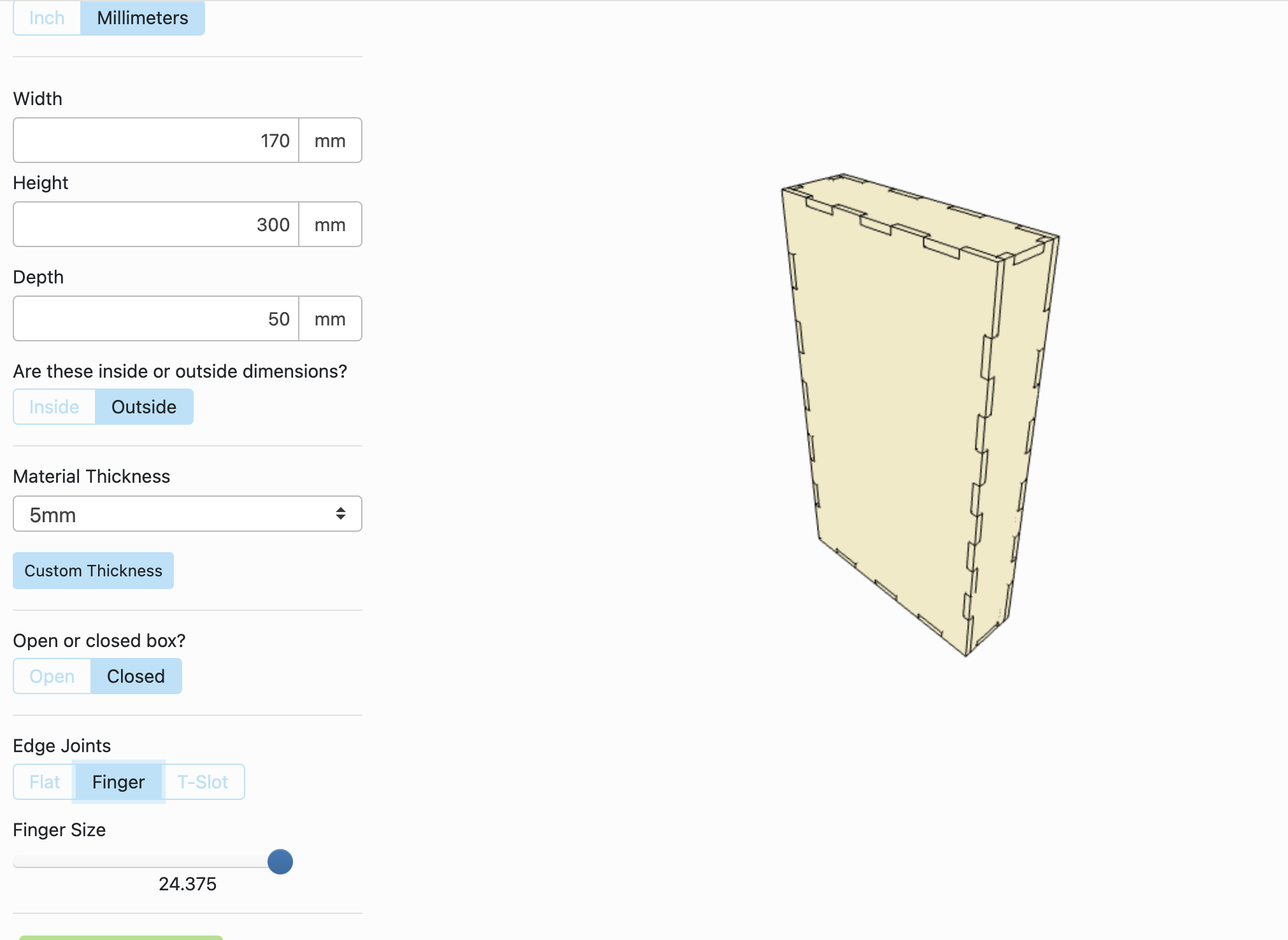
- Wood with a thickness of 5 mm
Measurements of the box:
- Height: 300 mm
- Width: 170 mm
- Depth: 50 mm
Technique: Laser cut
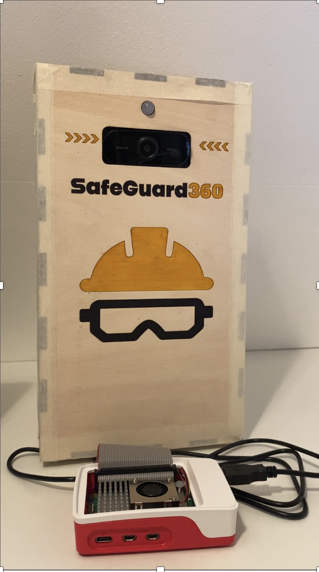
Now that the model is up and running with a functional UI and sensors, let's move on to building the physical model. We'll call this the "maker part." The vision for this component is to function like a stoplight, scanning employees wearing their PPE gear. I envision this as a box that houses the Freenove board and also mounts the camera and LED lights. During the sketching phase, I measured all the items to ensure they would fit on my board. Then, I used MakerCase to design a box. For my project, I used the following measurements to create the box.
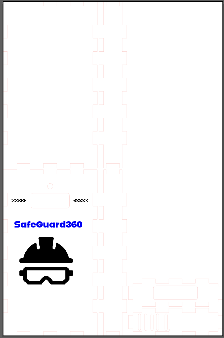
From there, I downloaded the SVG file and opened it in Adobe Illustrator to make some changes and add designs. In the picture, you can see where I created spaces for mounting the camera and LED light (be precise with your measurements, and consider adding 1 or 2 mm to account for any inaccuracies). At the top, I added rasters to allow sound to pass through. Lastly, I added a design to make the box visually appealing.
The End
This concludes my instructable. I hope you found my explanation helpful and enjoyed creating this product. If anything is unclear, please feel free to ask, and I welcome any uplifting comments! :)
Ps: This is the link to my GitHub Repo.