ST7920 LCD With ATmega328 in Atmel Studio Using SPI and the U8g2 Library
by VB96 in Circuits > Microcontrollers
7153 Views, 6 Favorites, 0 Comments
ST7920 LCD With ATmega328 in Atmel Studio Using SPI and the U8g2 Library
LCD Tutorial for University/hobbyist projects.
The following is a tutorial on using the ST7920 LCD with the ATmega328 microcontroller using Atmel Studio via the SPI interface. I have used the U8g2 Library, https://github.com/olikraus/u8g2
There are many tutorials on how to control the LCD using an Arduino, but I couldn't find many on how to use the LCD in Atmel Studio. There was a great one here, https://github.com/olikraus/u8g2/wiki/u8g2as7 which I used to learn how to do this, but several fine details were missing, which made it hard to follow.
I've tried to add every detail to get the LCD working in Atmel Studio.
Have fun!
Supplies
- ATmega328p microcontroller
- ST7920 LCD screen
- Breadboard
- Jumper wires
- Microcontroller programmer (I have used the USBasp programmer, your choice!)
- Pushbutton (optional)
- Reset Resistor (10k ohm)
Microcontroller Setup
I assume that you have the microcontroller working in Atmel Studio. There are plenty of tutorials on how to set up the ATmega328 on a breadboard and get a simple blink program working in Atmel Studio. These are some great ones:
https://www.jameco.com/jameco/workshop/jamecobuild...
https://www.arduino.cc/en/main/standalone
I have my ATmega328 operating at 8MHz using an internal crystal, set by changing the fuse bits from the factory default 1MHz. I use the following to set fuse bits: https://github.com/zkemble/AVRDUDESS, it is a clean interface and provides all necessary functionality. Careful when fusing bits - once again, many tutorials out there if you want to set your microcontroller to operate at a desired frequency.
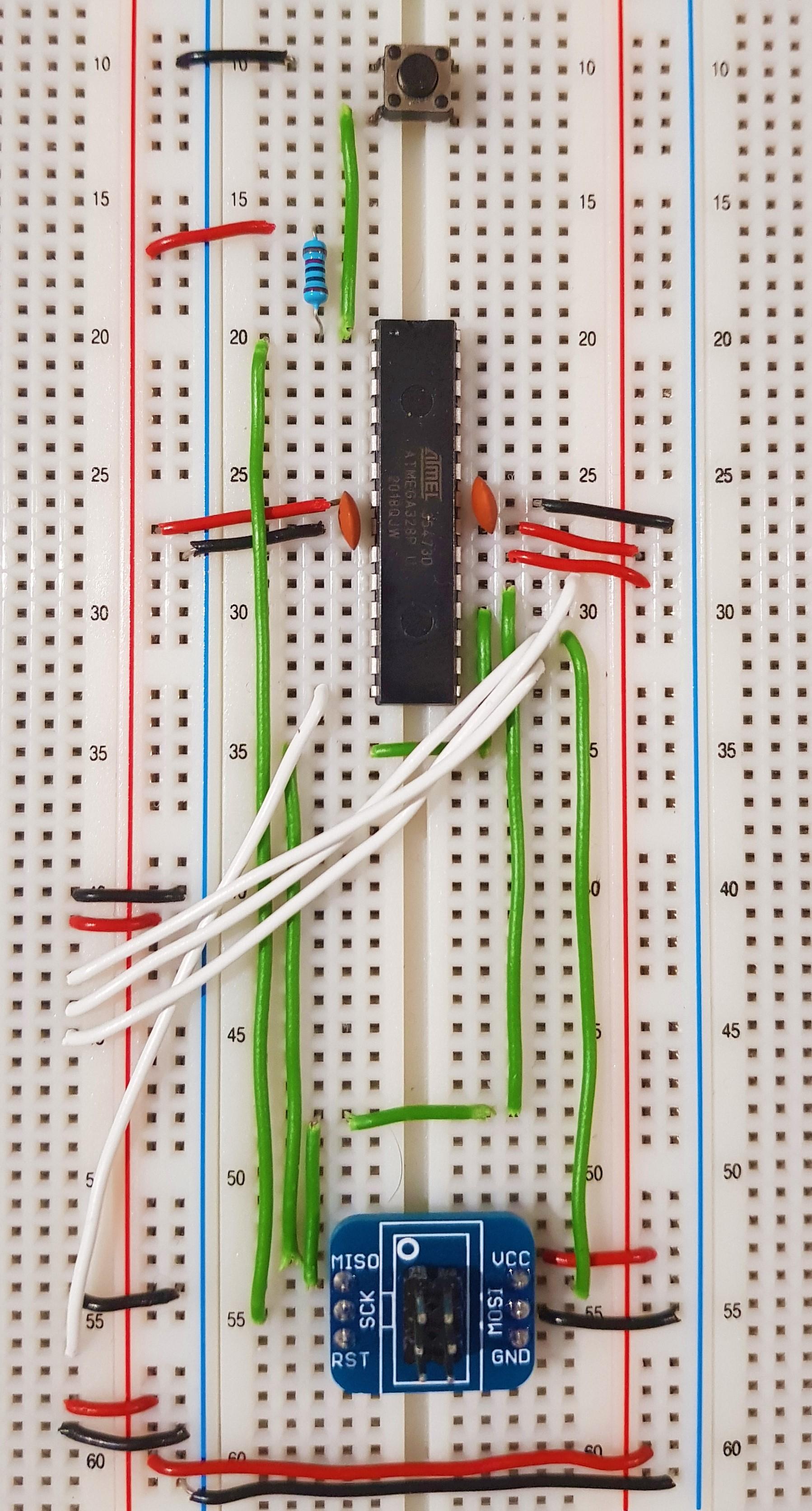
Connect the LCD Screen
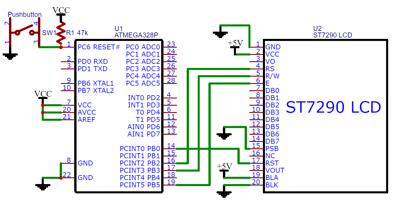
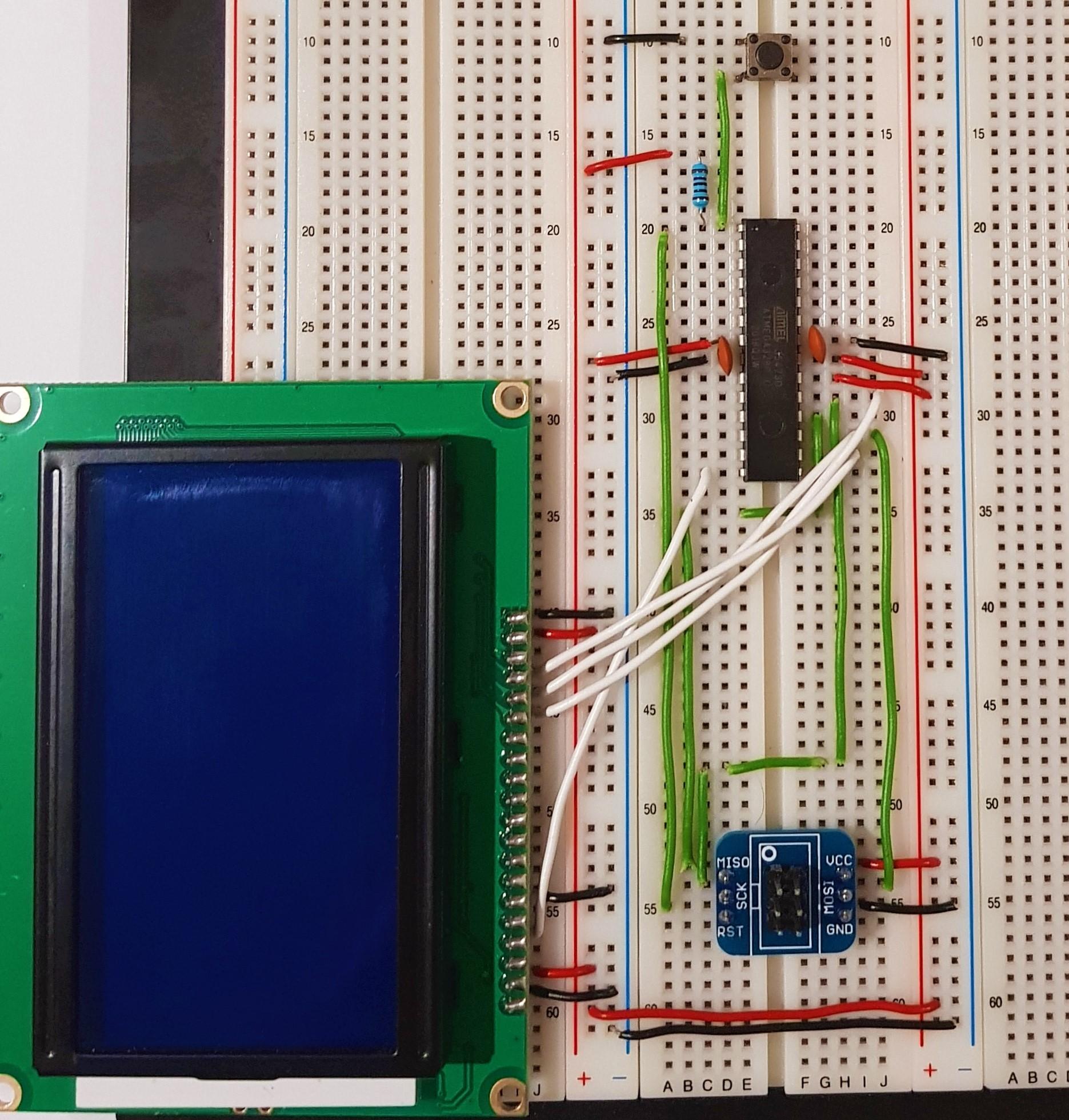
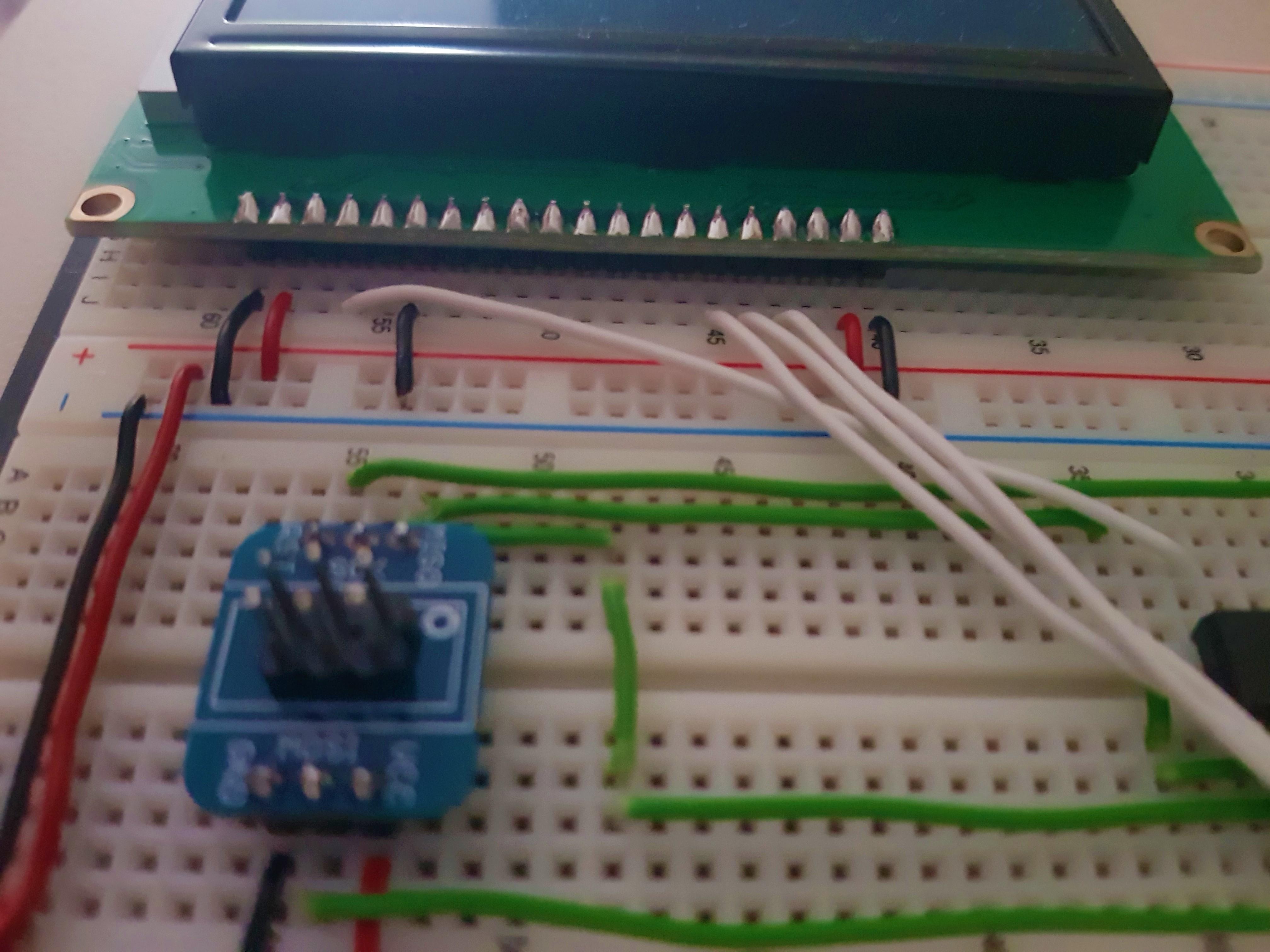
The first step is to set up the hardware. I have provided the schematic above and the pin mapping below.
LCD PIN ------> ATmega328 PIN
GND ------> GND
VCC ------> +5V
RS ------> PB2
R/W ------> PB3
E ------> PB5
PSB ------> GND
RST ------> PB0
BLA ------> +5V
BLK ------> GND
Open Atmel Studio
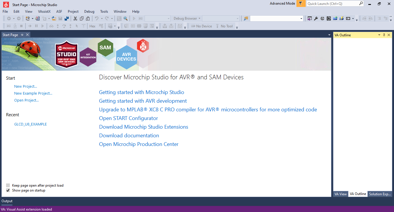
Getting to the software, the following goes through the steps one by one.
First, open Atmel Studio (Microchip Studio is the newer version).
Make a New Executable Project
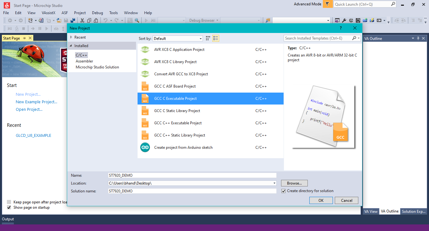
Make a new executable project by selecting the GCC C executable project option.
Select the Microcontroller
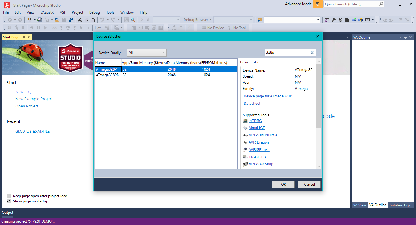
Select the microcontroller you are using. I am using the ATmega328P.
Click ok to proceed.
Replace the Main.c Code
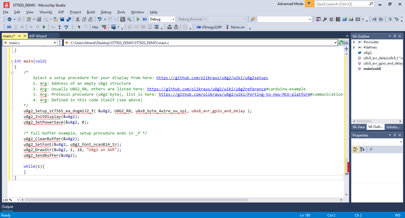
Open the main.c file and replace the code with that at https://github.com/olikraus/u8g2/blob/master/sys/a...
This is the main file.
Find the Correct LCD Initializer
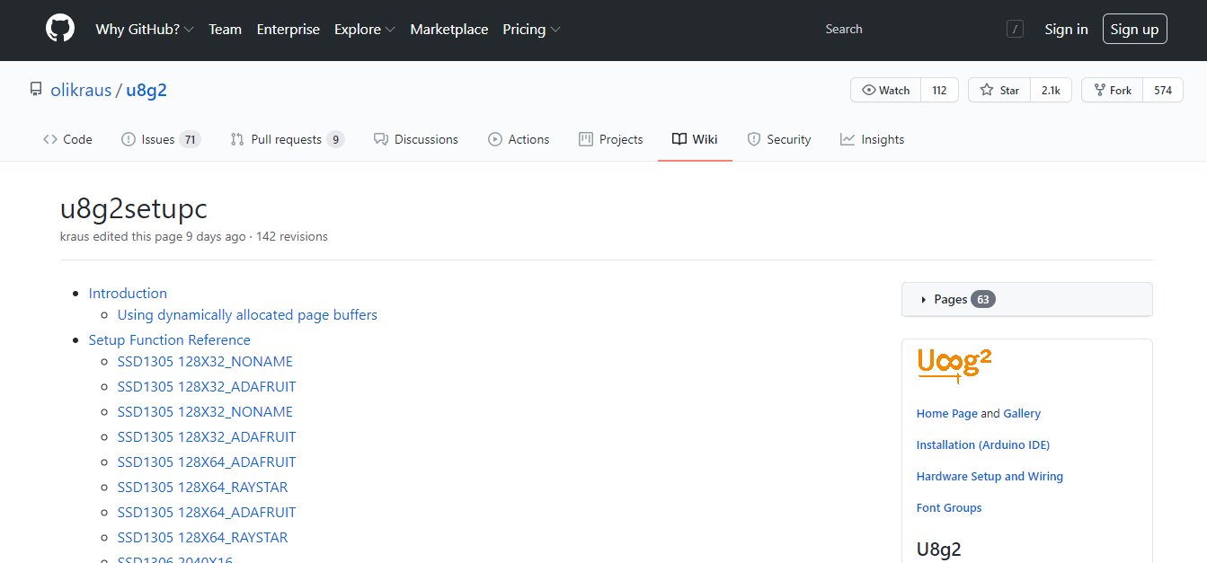
Head over to https://github.com/olikraus/u8g2/wiki/u8g2setupc to find the correct initializer for the LCD being used.
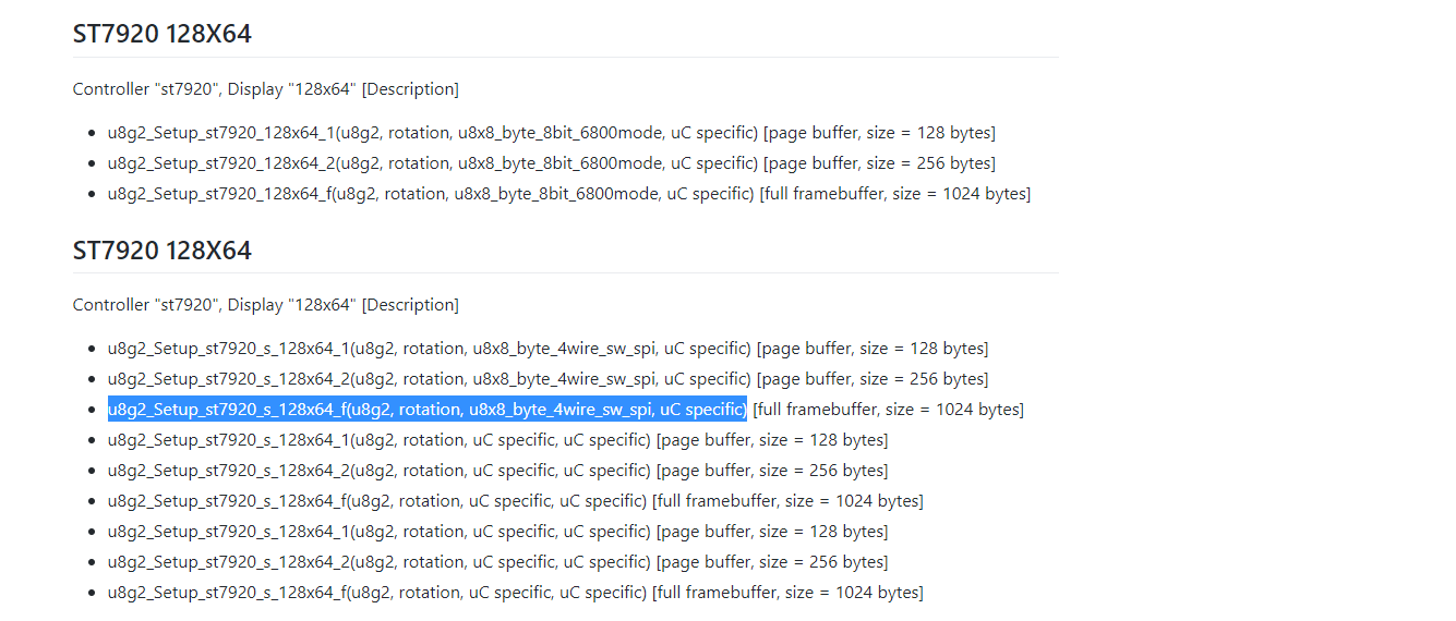
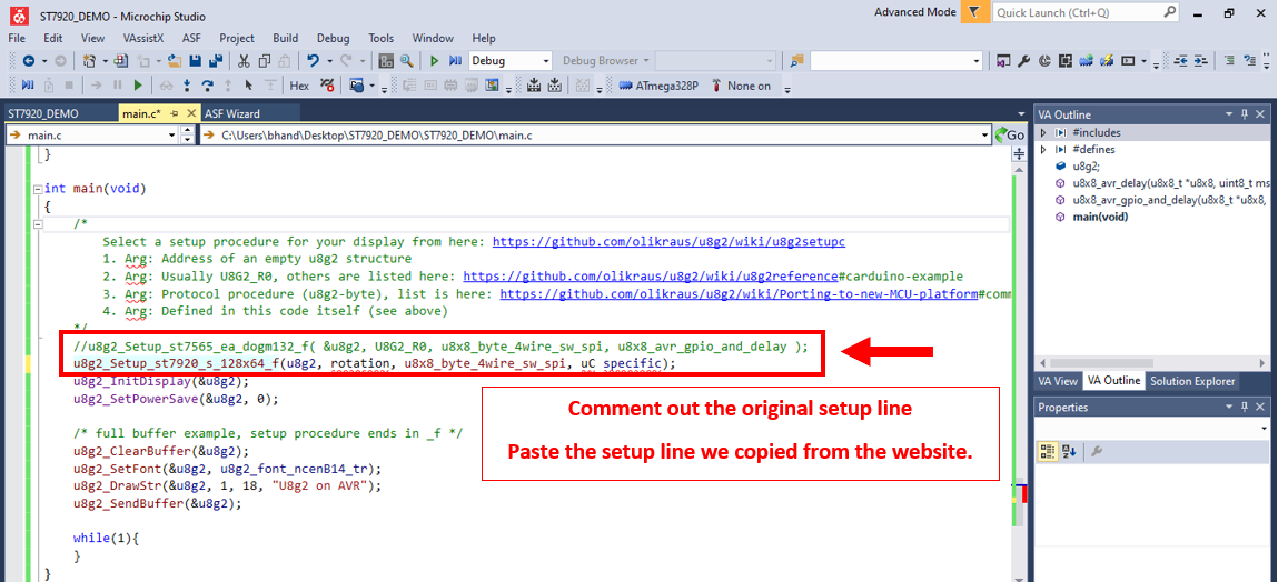
We are using SPI communication, so we select that setup line and paste it into the Atmel main function as shown in the last image. The following line is copied into the main function, replacing the original setup line.
We change:
u8g2_Setup_st7565_ea_dogm132_f( &u8g2, U8G2_R0, u8x8_byte_4wire_sw_spi, u8x8_avr_gpio_and_delay );
to:
u8g2_Setup_st7920_s_128x64_f(u8g2, rotation, u8x8_byte_4wire_sw_spi, uC specific);
Change the Setup Line Arguments
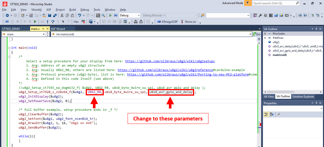
We need to supply the setup function with the correct parameters. Using the example originally provided, we change:
u8g2_Setup_st7920_s_128x64_f(u8g2, rotation, u8x8_byte_4wire_sw_spi, uC specific);
to
u8g2_Setup_st7920_s_128x64_f(&u8g2, U8G2_R0, u8x8_byte_4wire_sw_spi, u8x8_avr_gpio_and_delay);
Download the U8g2 Library
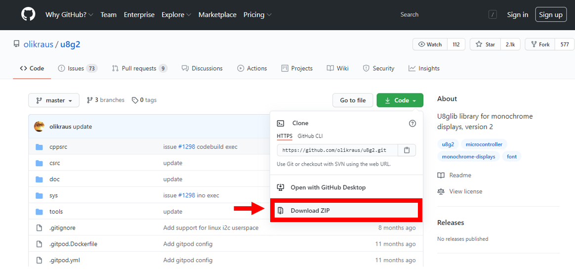
Download the library from the GitHub page: https://github.com/olikraus/u8g2 or directly from https://github.com/olikraus/u8g2/archive/master.zi...
Extract the files - we will need the file path in the next steps.
Head to the Solution Explorer
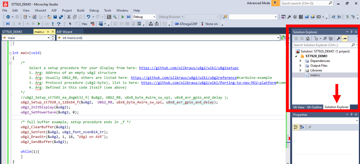
Head to the solution explorer.
Add Existing Item
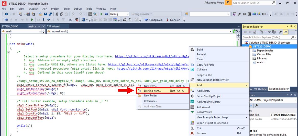
Click on the filename, 'ST7920_DEMO', and click on the add existing item option.
We are now going to add the library files.
Add Library Into the Atmel Solution
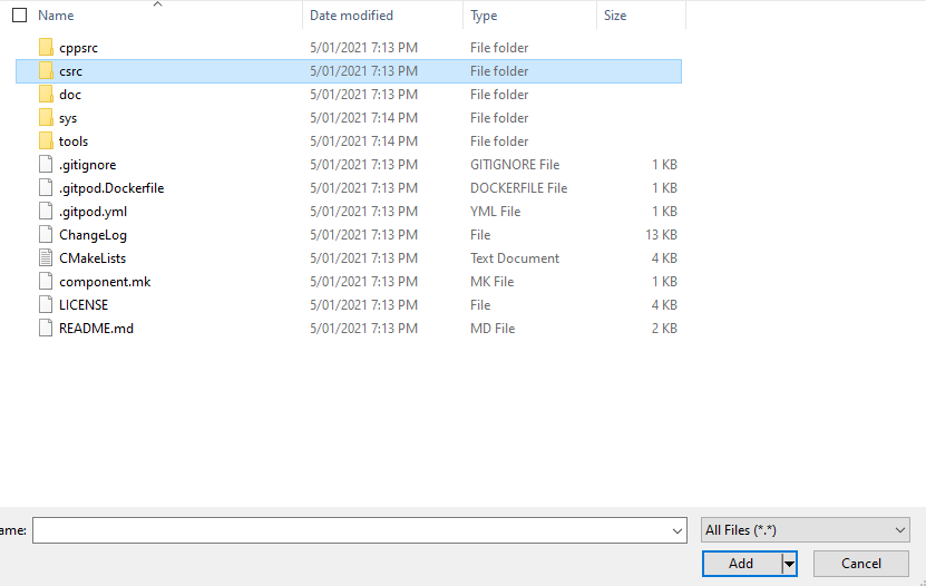
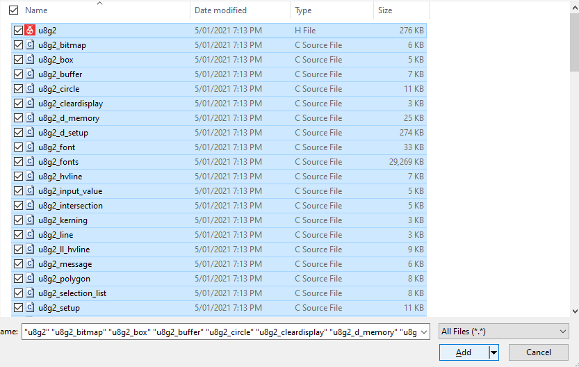
Once the add existing item option is clicked, redirect to the path of the extracted library and head into the csrc folder.
Click into the folder and select all the files. Then click add.
The next step is to edit the file properties so the library can be accessed.
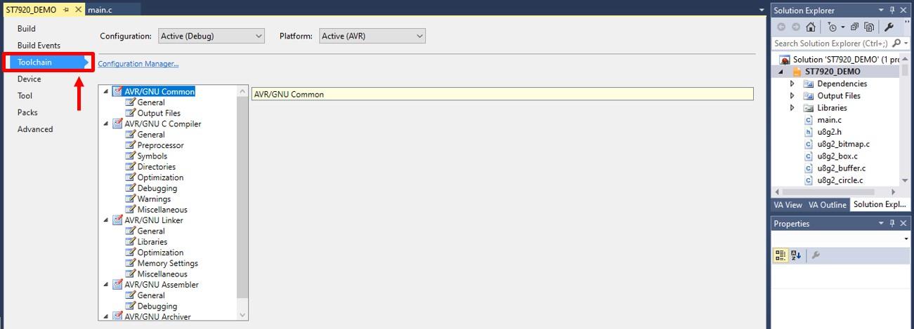
Go to File Properties --> Toolchain
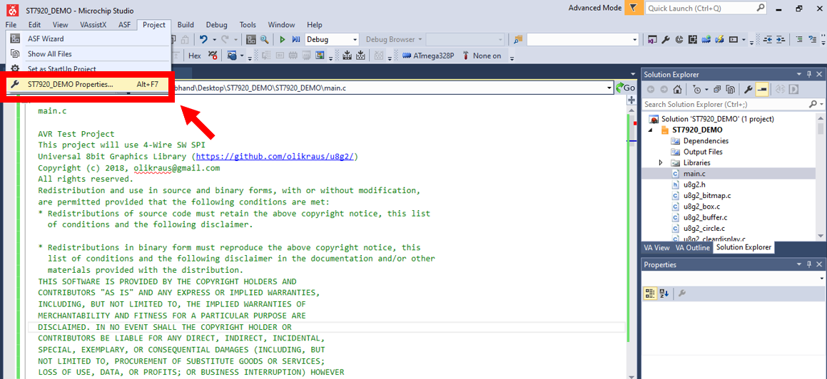
1. Head to the file Properties
2. Select the Toolchain option from the side menu
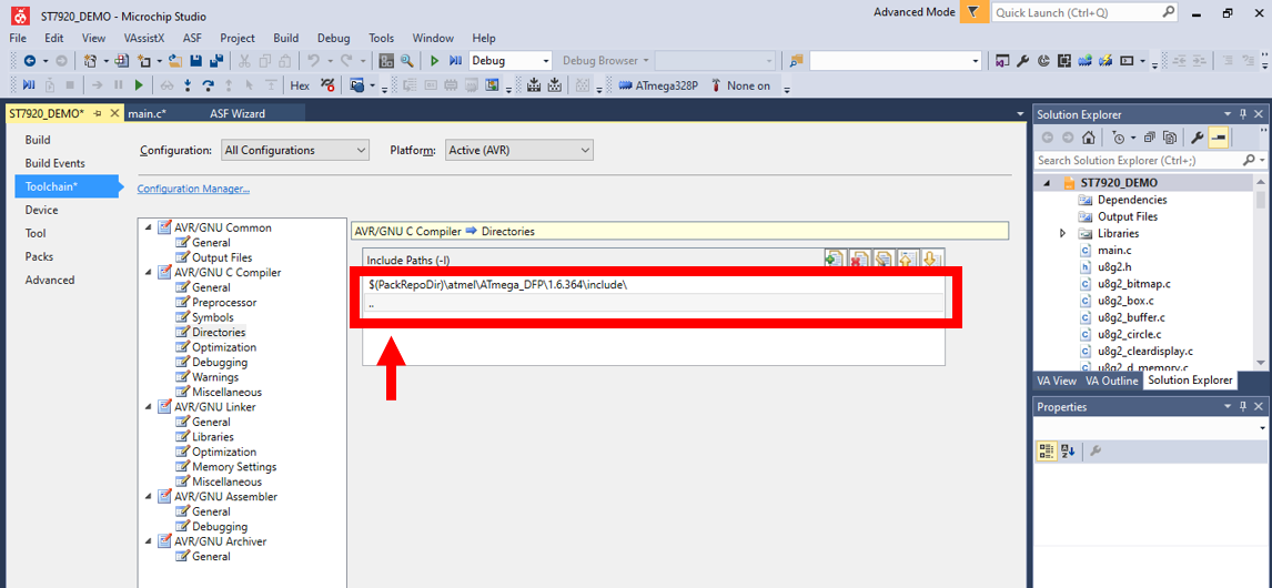
Add the Directories
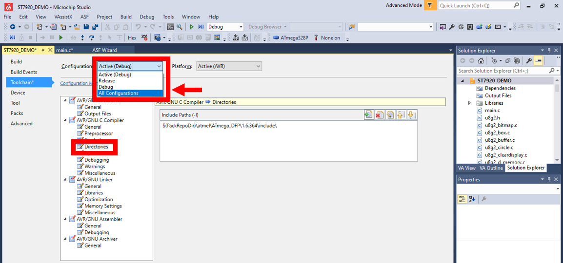
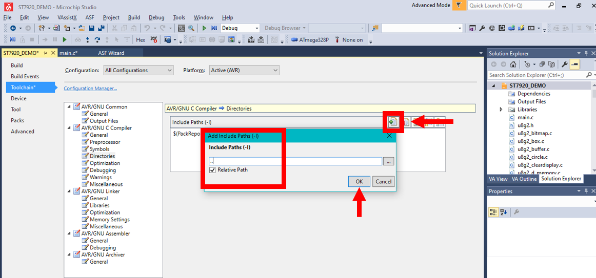
1. Select Directories from the side menu
2. Select All Configurations for the Configuration type
3. Click on the Add Item button
4. Add .. as an Include Path
5. Check that the path was added
Add the F_CPU Symbol
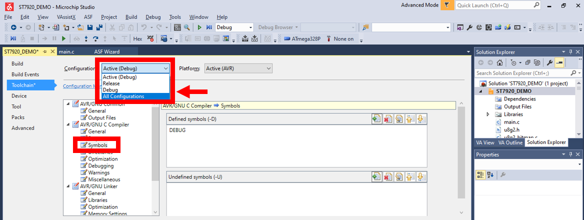
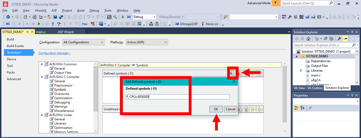
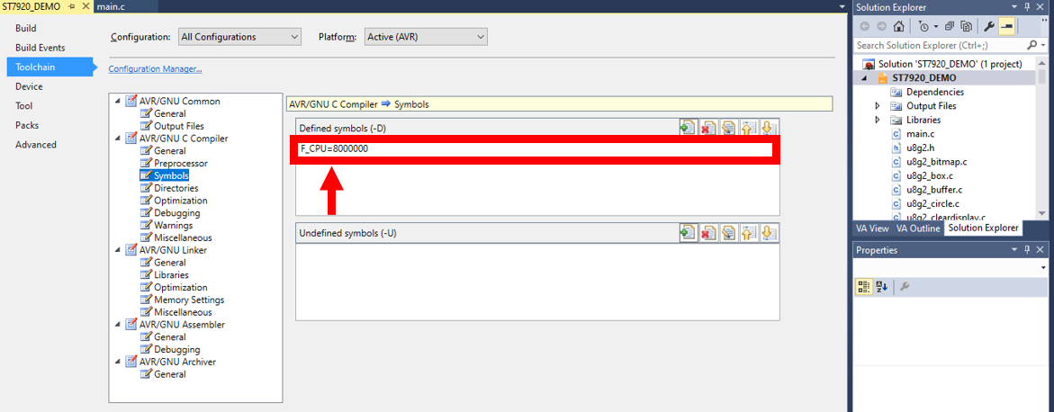
1. Still in file Properties, Toolchain
2. Select Symbols from the side menu
3. Select All Configurations for the Configuration type
4. Click on the Add Item button
5. Add F_CPU=8000000 as a symbol
My microcontroller clock is set to 8000000 (8MHz), the factory default is 1000000 (1MHz).
6. Check that the symbol was added
I had errors when building the solution when I added:
F_CPU = 8000000
and no errors when I added:
F_CPU=8000000
Note that adding spacing between the F_CPU, = and 8000000 leads to errors.
Build Solution and Upload!
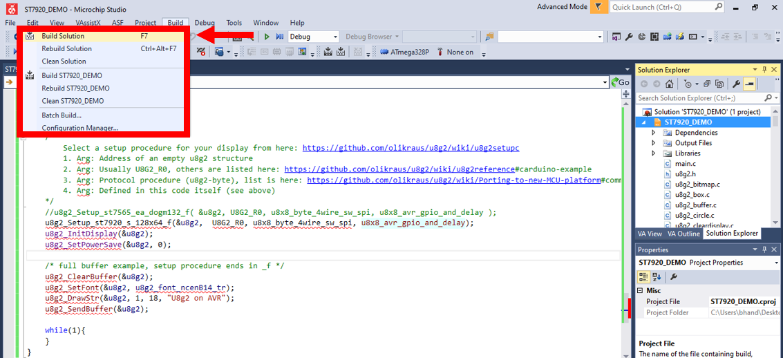
Build the solution and upload it to the microcontroller.
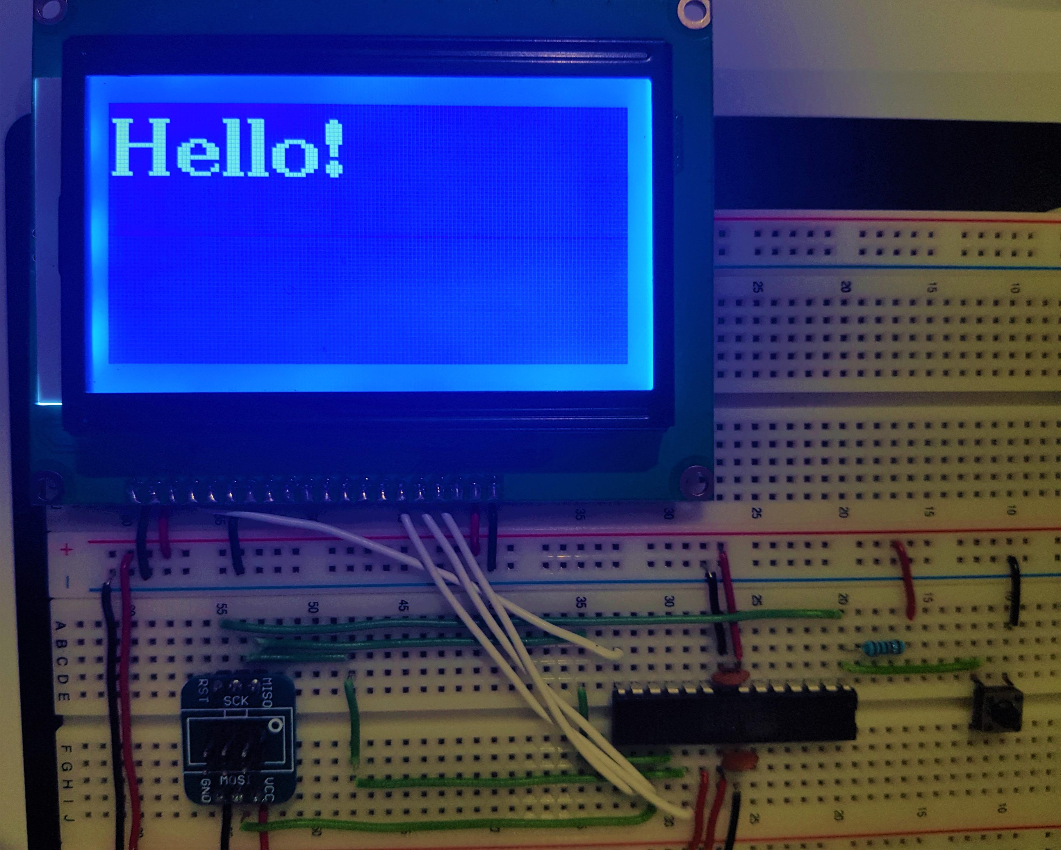
Not Displaying Anything? Adjust the Screen Contrast
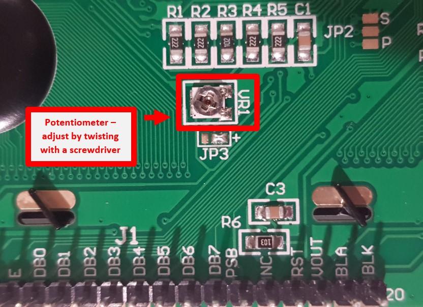
Please ensure that the display contrast has been adjusted. There are two ways to do this.
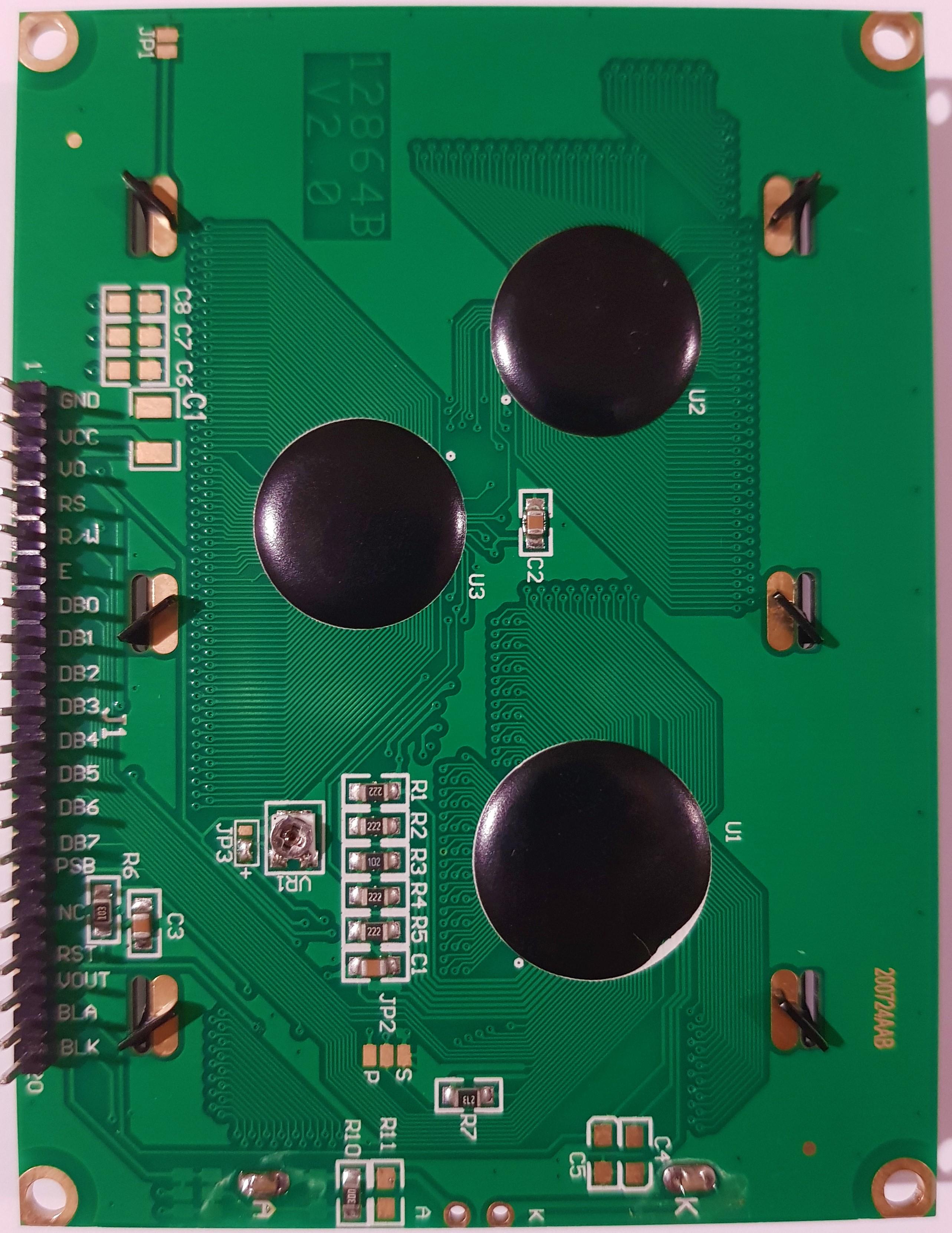
1. If the LCD comes with a soldered potentiometer, twist the potentiometer using a screwdriver until the contrast is visible.
or
2. If the LCD does not have a potentiometer soldered to the back, attach a resistor with a value of between 200 to 10000 ohms to pin VO as seen above. Adjust the value of the resistor to achieve an optimal contrast. Alternatively, a potentiometer could be used to adjust the contrast.