SPICE Netlist Simulation Using NI LabVIEW & NI Multisim
by Bits4Bots in Circuits > Electronics
963 Views, 1 Favorites, 0 Comments
SPICE Netlist Simulation Using NI LabVIEW & NI Multisim

Do you have an old library of SPICE files or new ones from other circuit design software like KiCAD you'd like to simulate or analyze or vice versa? Would you like to modify the circuit inputs in real-time and see the outputs as a result?
Here is a step-by-step process to run text-based SPICE netlist simulations from NI LabVIEW. NI Multisim is used as the simulation engine and it is run in a background process connected to LabVIEW using the LabVIEW Multisim API Toolkit.
Create and modify a netlist file from a Multisim circuit file
Create and modify a SPICE nutmeg command file
Use LabVIEW to build a VI that will execute the SPICE nutmeg command file
Display results from the simulation
Nutmeg is a post processor for SPICE it takes the raw output file created by spice -r and plots the data on a graphics terminal or a workstation display.
The PDF is attached for advanced users of National Instruments who would like to design the Multisim circuit and LabView block diagram on there own.
For the rest of us, we will use the prebuilt sample files provided to simply "Run" the SPICE files for analysis.
Follow us for more cool projects and visit us at www.bits4bots.com
Downloads
Supplies
Requirements
NI LabVIEW 2013 or higher
NI Multisim 14.0 or higher (Power Pro or Education Editions)
LabVIEW Multisim API Toolkit (installed by Multisim)
Files in the SPICE Command Line folder located in the Multisim samples folder
Locate Files
In a typical Multisim installation, the samples folder is in this location:
C:\Users\Public\Documents\National Instruments\Circuit Design Suite <version>\samples\LabVIEW Multisim API Toolkit\
I am currently running Multisim 14,3 so my files were located here:
C:\Users\Public\Documents\National Instruments\Circuit Design Suite 14.3\samples\LabVIEW Multisim API Toolkit\SPICE Command Line
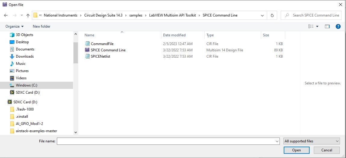
Another way to find the samples folder in Multisim is to select File»Open samples, and take note of the folder location in the explorer window.
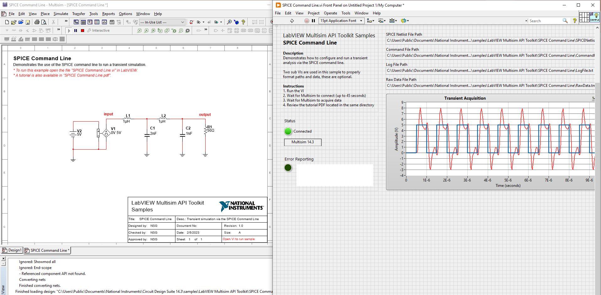
Run Multisim 14.x

Open the Spice Command Line ms design file.
Run LabView 2021


Open a blank design.
Next, open the prebuilt vi. The file name is SPICE Command Line vi
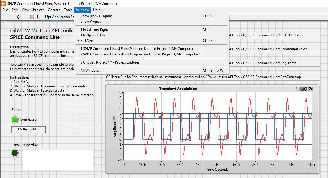
To view the block diagram click the "Windows" tab then select "Show Block Diagram" from the dropdown menu in the LabView Front Panel.
Simulate the Multisim Circuit - Analyze in LabView

To simulate the SPICE Command Line in LabView click the white arrow icon. The transient acquisition graph will start to populate the data from the Multisim circuit.
The log of the results is saved in a RawData.tmp file.
See the LabView block diagram to see how this is accomplished.
Two subVIs:
- sub Create Local Paths VI and
- sub Data Parser VI
which are custom made, allows you to create your own if you wish, or for convenience use these subVIs provided.
_________________________________________________________________________________________
Here is what my RawData.tmp file looks like for points 1-5 and 439-447:
Title: ** SPICE Command Line **
Date: Sun Feb 5 03:19:25 2023
Plotname: Transient Analysis
Flags: real
No. Variables: 3
No. Points: 448
Variables:
0 n1 time time
1 n2 voltage V(input)
2 n3 voltage V(output)
Values:
0 0.000000000000000e+00
0.000000000000000e+00
0.000000000000000e+00
1 2.000000000000000e-09
0.000000000000000e+00
0.000000000000000e+00
2 4.000000000000000e-09
0.000000000000000e+00
0.000000000000000e+00
3 8.000000000000000e-09
0.000000000000000e+00
0.000000000000000e+00
4 1.600000000000000e-08
0.000000000000000e+00
0.000000000000000e+00
5 3.200000000000000e-08
0.000000000000000e+00
0.000000000000000e+00
439 9.613238626197609e-06
5.000000000000000e+00
4.435451045444346e+00
440 9.653080484181489e-06
5.000000000000000e+00
7.191203675414505e+00
441 9.702830176830998e-06
5.000000000000000e+00
7.866990590203802e+00
442 9.742089605972989e-06
5.000000000000000e+00
6.587204646765869e+00
443 9.787203930557956e-06
5.000000000000000e+00
5.138618203987046e+00
444 9.831838995192895e-06
5.000000000000000e+00
4.570024884251302e+00
445 9.883862443507754e-06
5.000000000000000e+00
4.328877880904384e+00
446 9.939326395757750e-06
5.000000000000000e+00
4.188376596821053e+00
447 9.999999999999999e-06
4.999999999957648e+00
4.738785809050968e+00
Further Learning
Multisim also has an Arbitrary SPICE Block.
The Arbitrary SPICE Block is a special portless component that allows a netlist to be inserted directly within the simulation netlist. The Arbitrary SPICE Block provides the same SPICE/XSPICE support as inherently supported in NI Multisim, including PSpice device and parameter support.
How to Import a Netlist Using the Arbitrary SPICE Block:
- Open the Component Browser (Place > Component)
- In the Basic group, Basic Virtual family, select the Arbitrary SPICE Block and click OK
- Left-click to place the component on the schematic
- Double-click on the component to invoke its Component Properties
- Paste the SPICE netlist to be simulated.
- Click OK
Also, here's the link to see how you can use SPICE models in KiCAD.
SPICE Model Resources
Ready to try simulating SPICE models? Here are some resources in no particular order: