SMOL State Ornament
.jpg)
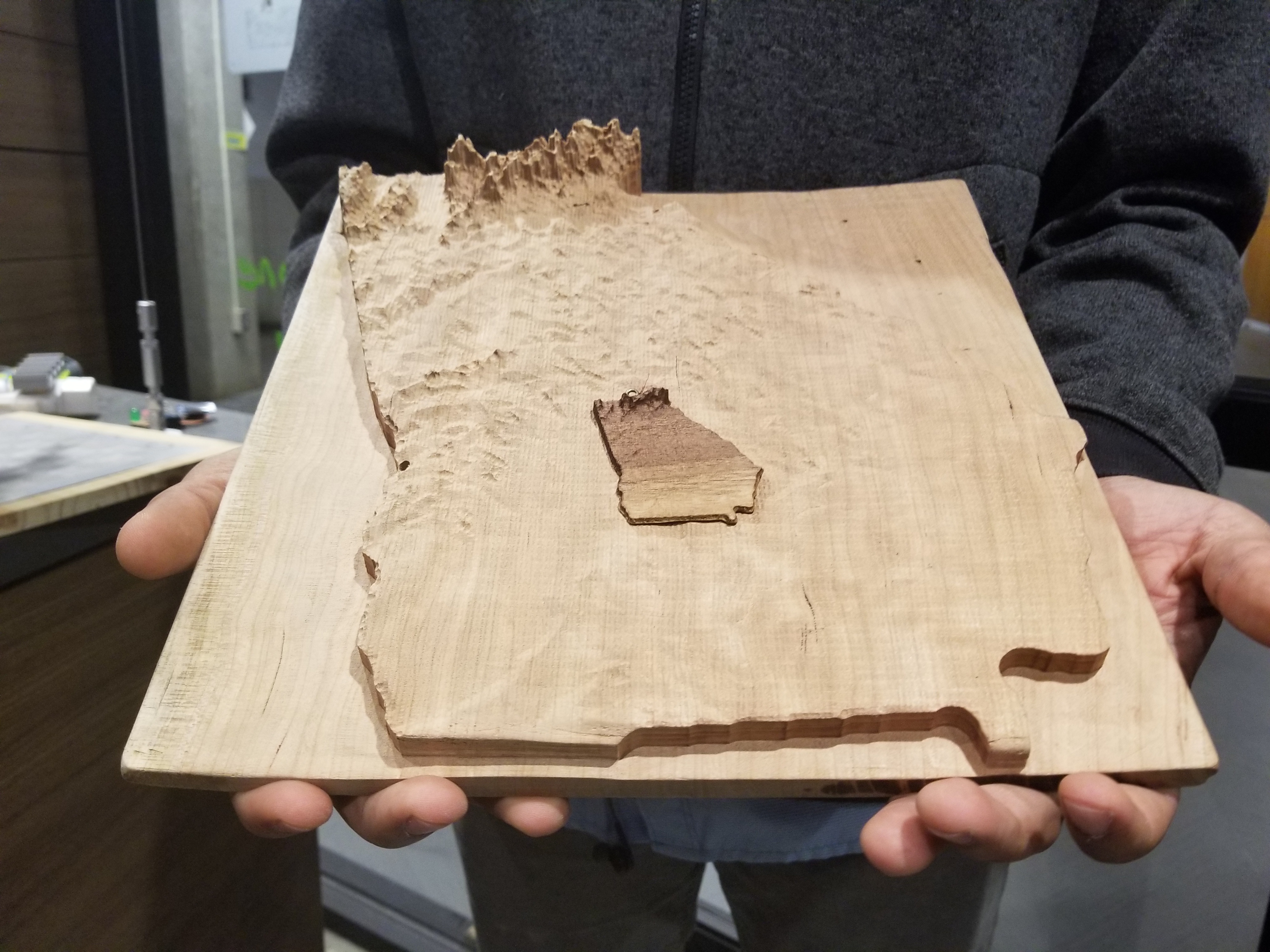
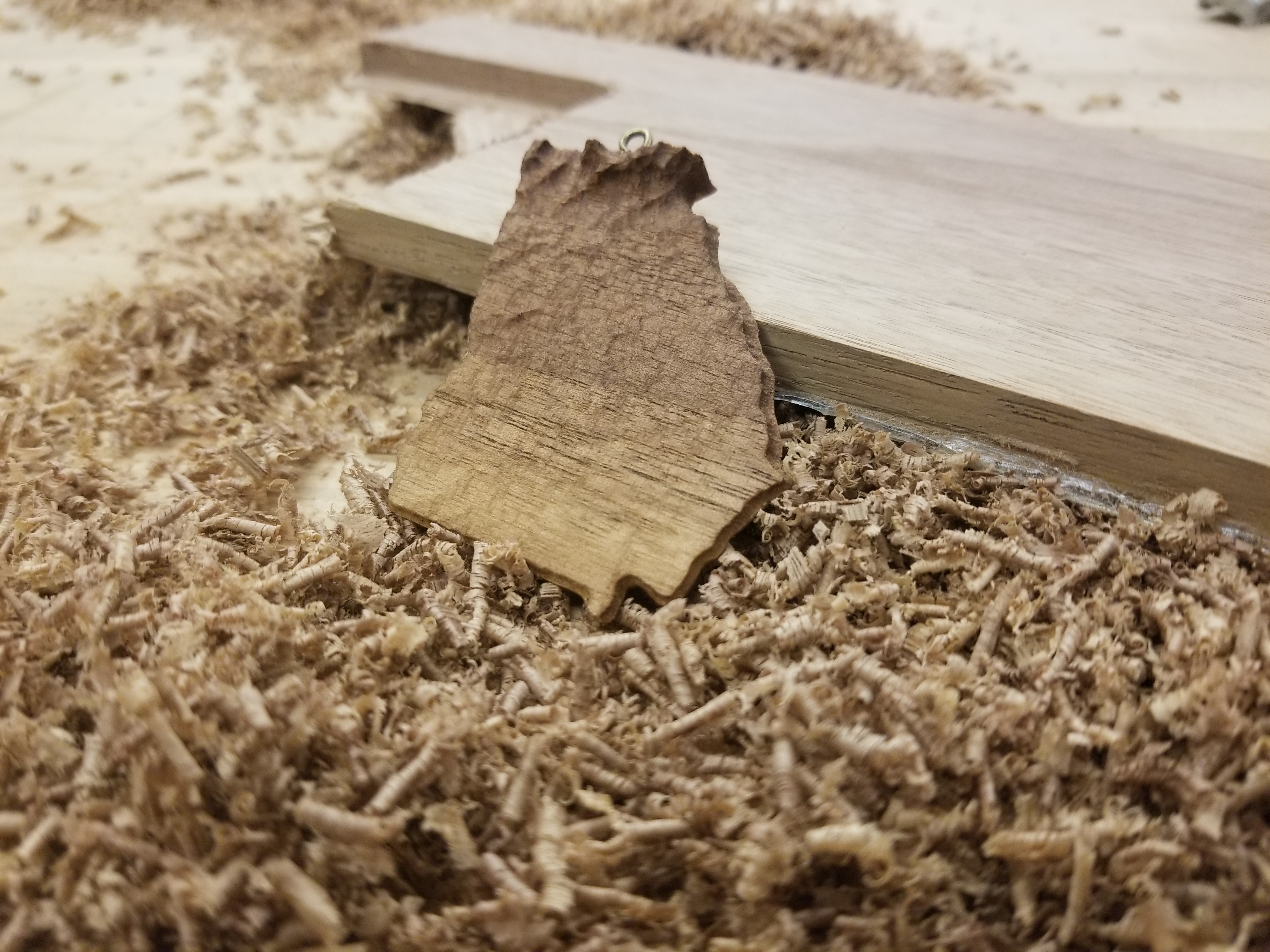
Hey everyone,
I find myself right after the holidays writing my first Instructable. I'm pretty excited to also enter my first contest. The idea to enter came from my girlfriend as I made her this ornament as a Christmas gift. She really loved it and suggested I share the knowledge. So, this is written for the Big & Small Contest.
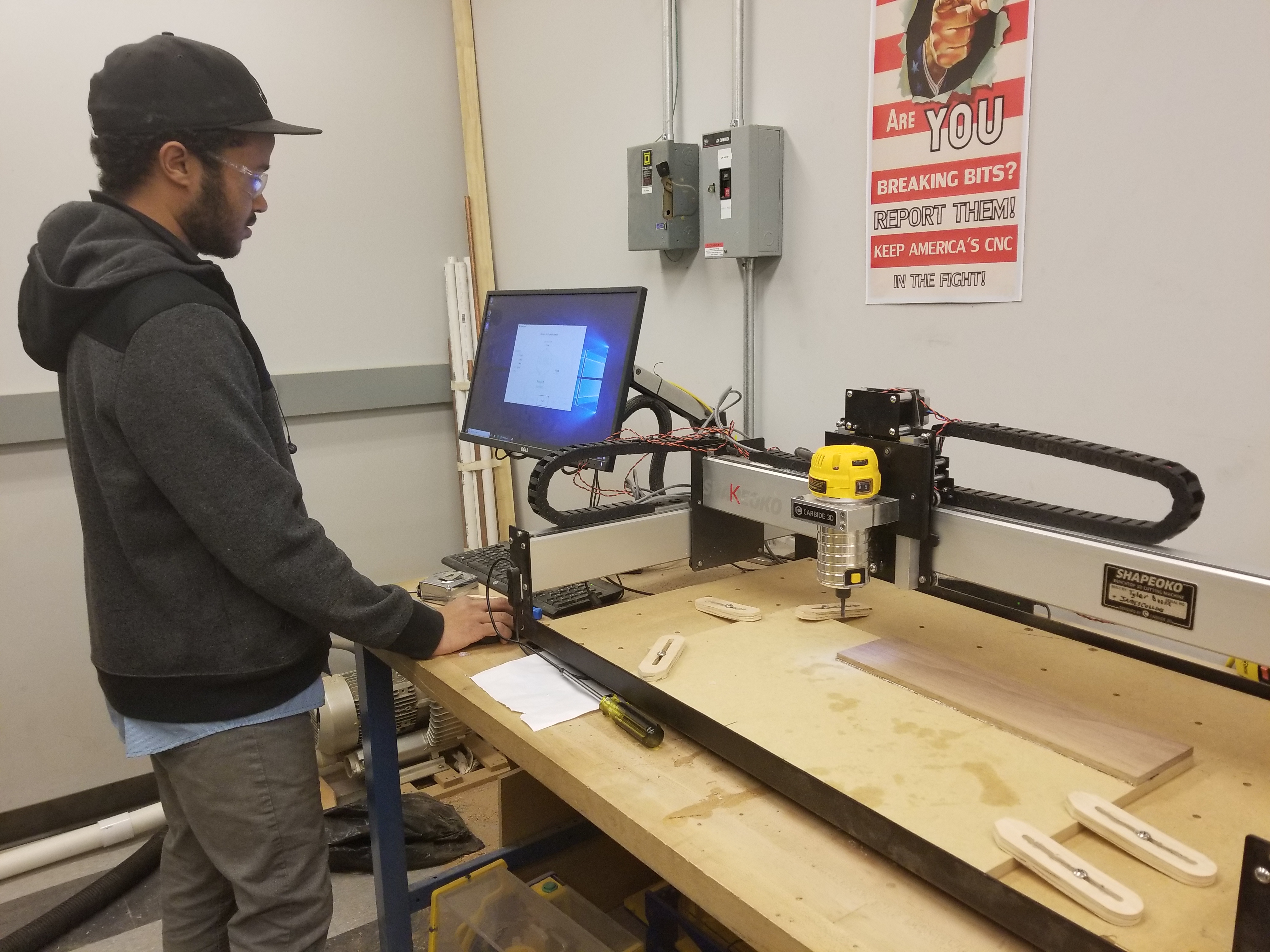
I have been fortunate enough to find my way into a great makerspace during my time at Georgia Tech. The Invention Studio is full of tools and knowledge that would be difficult to come by elsewhere, but I've noticed that we tend to overlook some of the more accessible machines in favor of our industry-grade equipment. Cue the Shapeoko XL.
I'm happy to share the method that I used to make a thoughtful and creative Christmas present, and to do so in a way that should be feasible to replicate for anyone who owns or has access to hobbyist grade CNC equipment. The method that I'll show you for converting/preparing CAM should work on most .stl files. Depending on your determination to make small objects, this method can be used to make things that are impractically small. After an hour of experimentation, we were even able to make a Georgia the size of a quarter!
What You Need
Tools:
- .25 in flat end mill
- .123 in tapered 3 flute ball end mill (an option featured here)
- CNC router of your choice ( Shapeoko XL featured here )
- Hot Glue Gun
- Mallet
- Putty Knife
- Clamp
- Drill
- Appropriately sized drill bit (1/32" for our eye-hook)
- Appropriately sized eye-hook (the one seen here comes from a cheap jewelry kit found on Amazon)
Stuff:
- Nice stock wood of your choice ( I used Walnut )
- Hot glue sticks
- Softer spoil board material ( I used scrap MDF from another project )
- Sandpaper
- Regular Printer Paper
- Paper Towels
- Mineral Oil
Software:
- Fusion 360
- Cura
- Carbide3D Post Processor File ( which should be automatically installed with Fusion 360 )
- Carbide Motion ( because we are using a Shapeoko )
Files:
- Raw Topographic Map Files ( thanks to Thingiverse user nlorang )
Prepare File for CAM Generation.
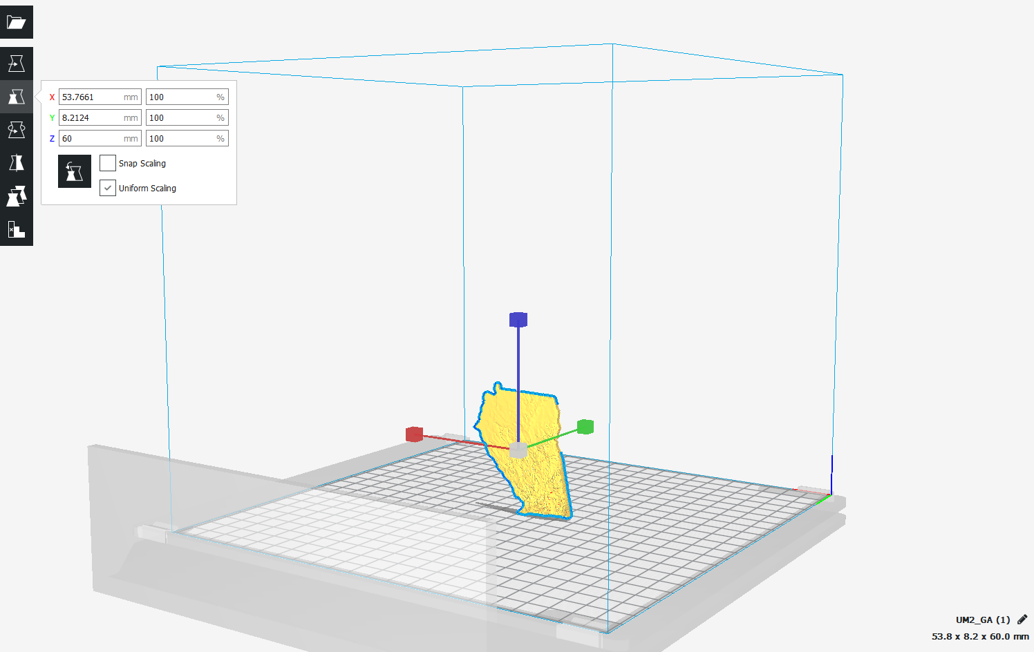
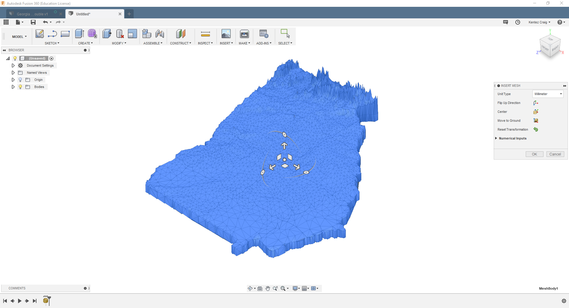
- Download and open the state file of your choosing in Cura:
- Once you've opened the file, proceed to rotate and scale it until you find the desired orientation and sizing. This model was scaled to be approximately 3 in tall in the longest dimension and was scaled uniformly. Additionally, the model was rotated to be aligned in the XY plane as closely as possible.
- When that's done, go to: File > Save As > (Select file type as .stl (ASCII) and give it a name)
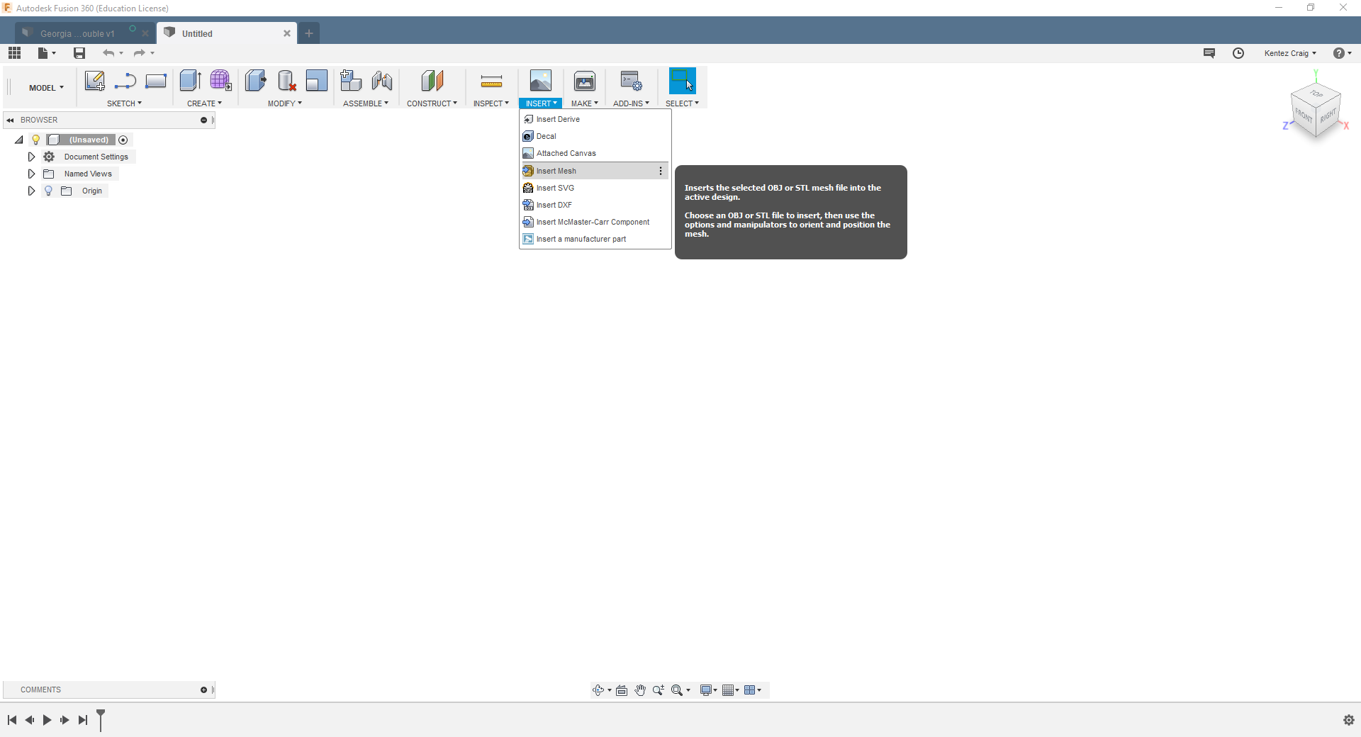
- Open a new design in Fusion 360:
- In Model View: Select the drop down menu labeled "Insert". Then, select "Insert Mesh". This will bring up a popup window to upload the .stl file we saved earlier. Once the model appears, there will be a little menu pop up menu titled "Insert Mesh". It is very important to change the import unit to match the units used in the Cura file we saved earlier. Once the model looks correct, click "OK". Save this file.
- If you would like to skip the preparation process or just follow along I have also uploaded the Fusion 360 file I made (SMOL State Ornament).
Downloads
Define CAM and Post Process
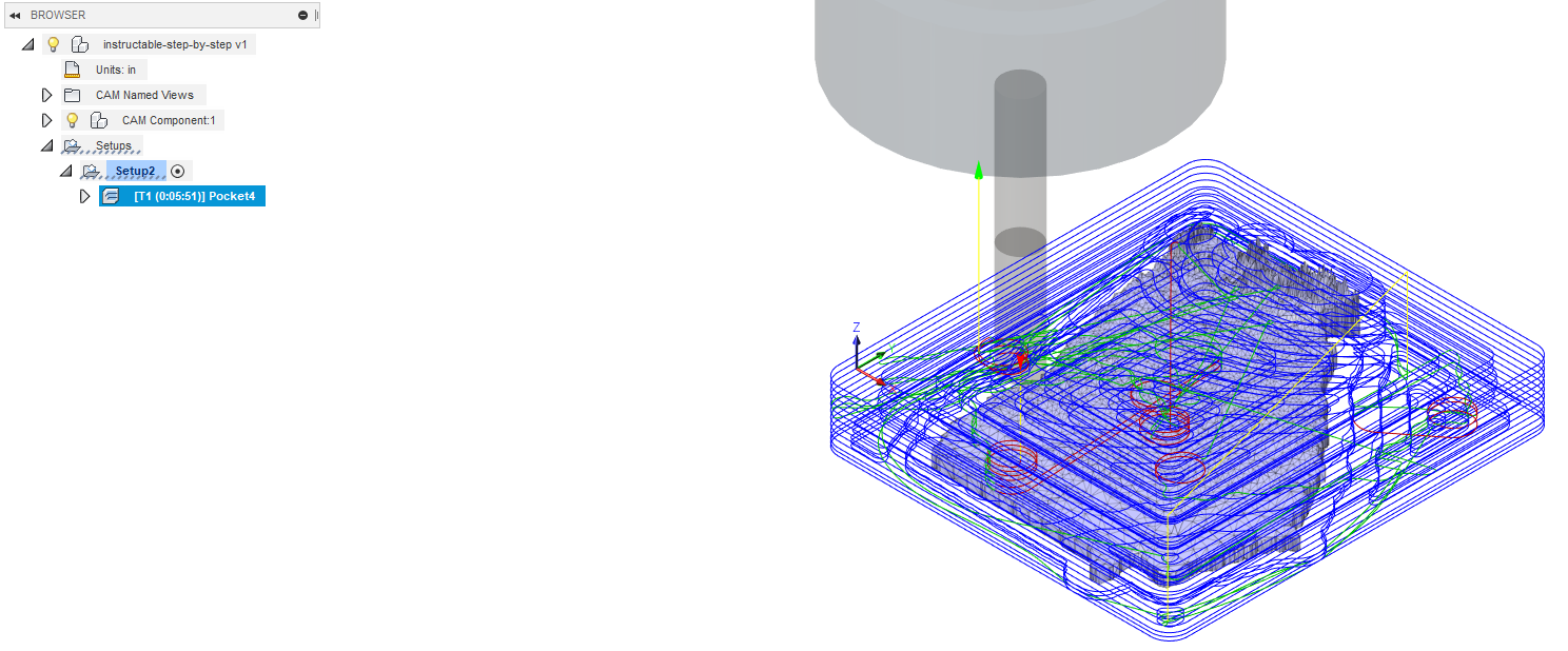
- Import the tool library I used if desired (Called Tooling.tools). Detailed instruction found here.
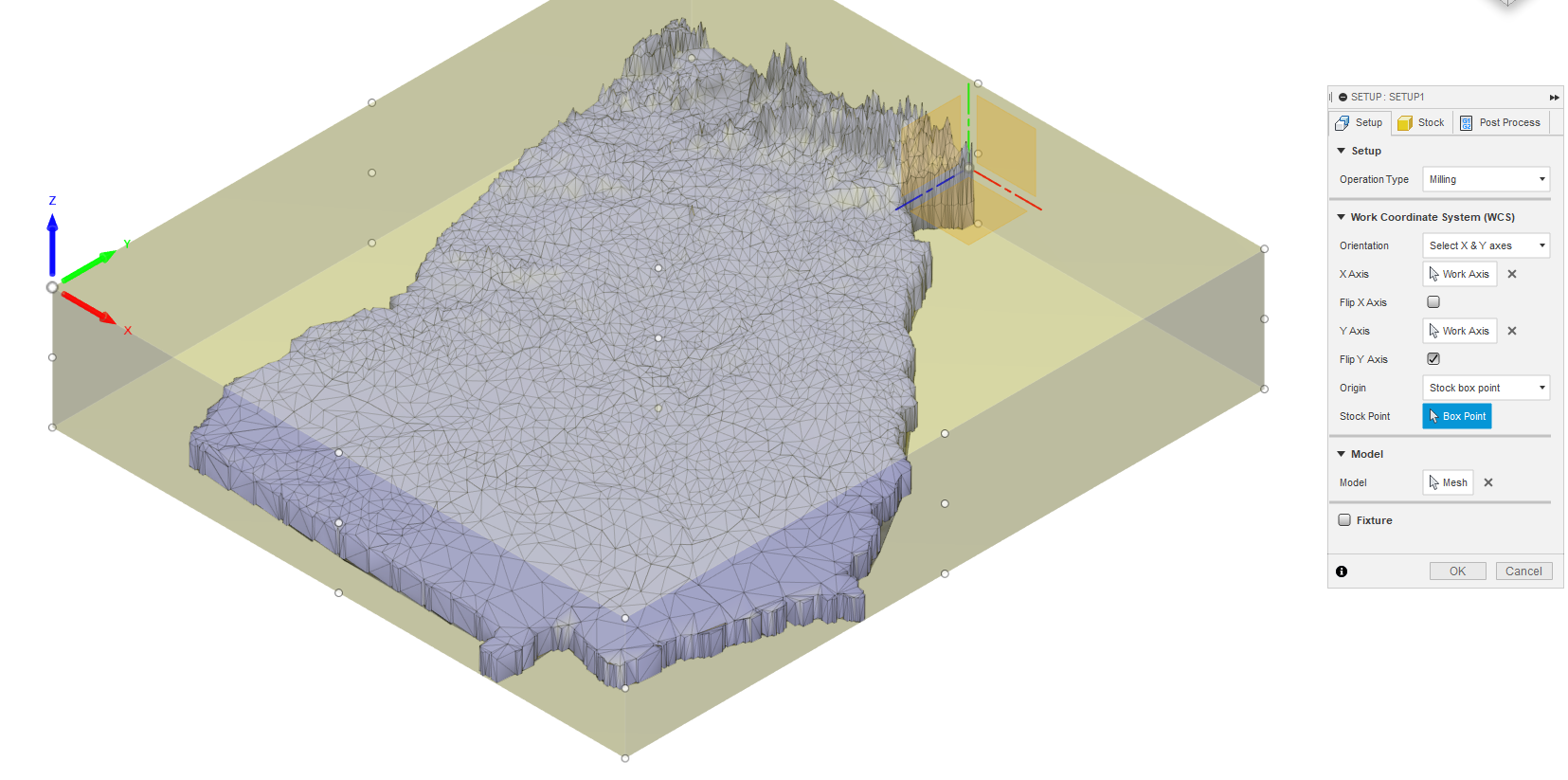
- Designate Stock Dimensions and Coordinate System:
- In the Setup Tab: Double-check that the operation type is set to "Milling". Click the Arrow button next to model, then mouse over and select the state model that is visible in the model space.
- To select the stock coordinate system - which determines how Fusion generates the toolpaths - select "Select X & Y axes" in the Orientation dropdown menu. Select the red axis as the X axis. Select the blue axis as the Y axis, and select the radio button next to "Flip Y Axis" if necessary. The goal is to make sure that the Z axis points upwards with respect to your model.
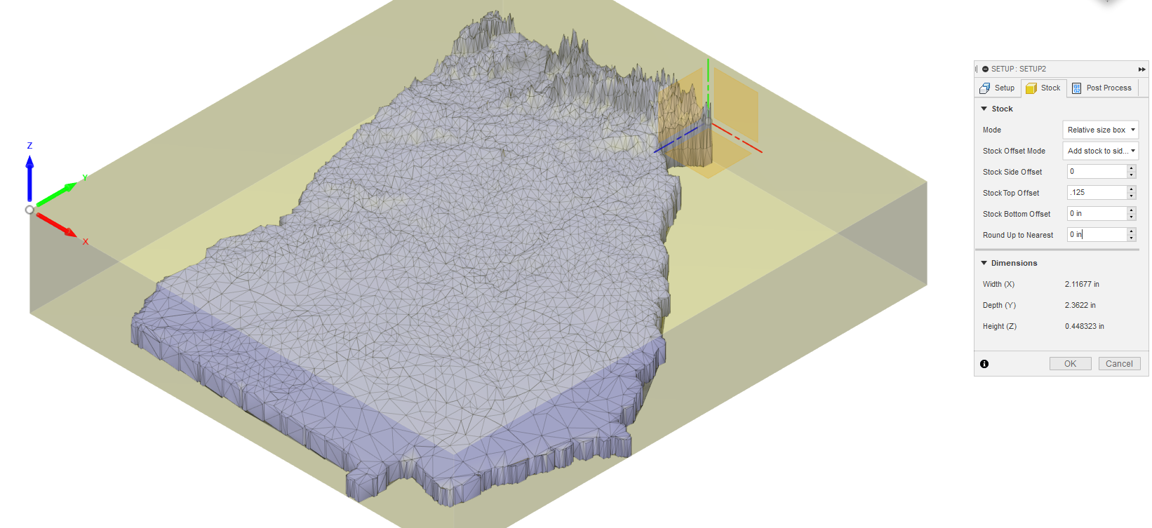
- In the Stock Tab: Manually zero out all offsets by typing 0 into all setting boxes. Record the Height (Z) value, as this is your required stock height (RSH).
- In the real world: Measure and record your actual stock height (ASH).
- In the Stock Tab: Alter the Stock Top Offset (STO) to reflect the following - STO = ASH-RSH. This will reflect exactly the depth that the machine will try to cut out the ornament. The thinness of the remaining stock relies entirely on your accuracy in measuring the ASH. If you want more material left - in lieu of tabs - decrease the stock top offset.
- Generate Roughing Pass:
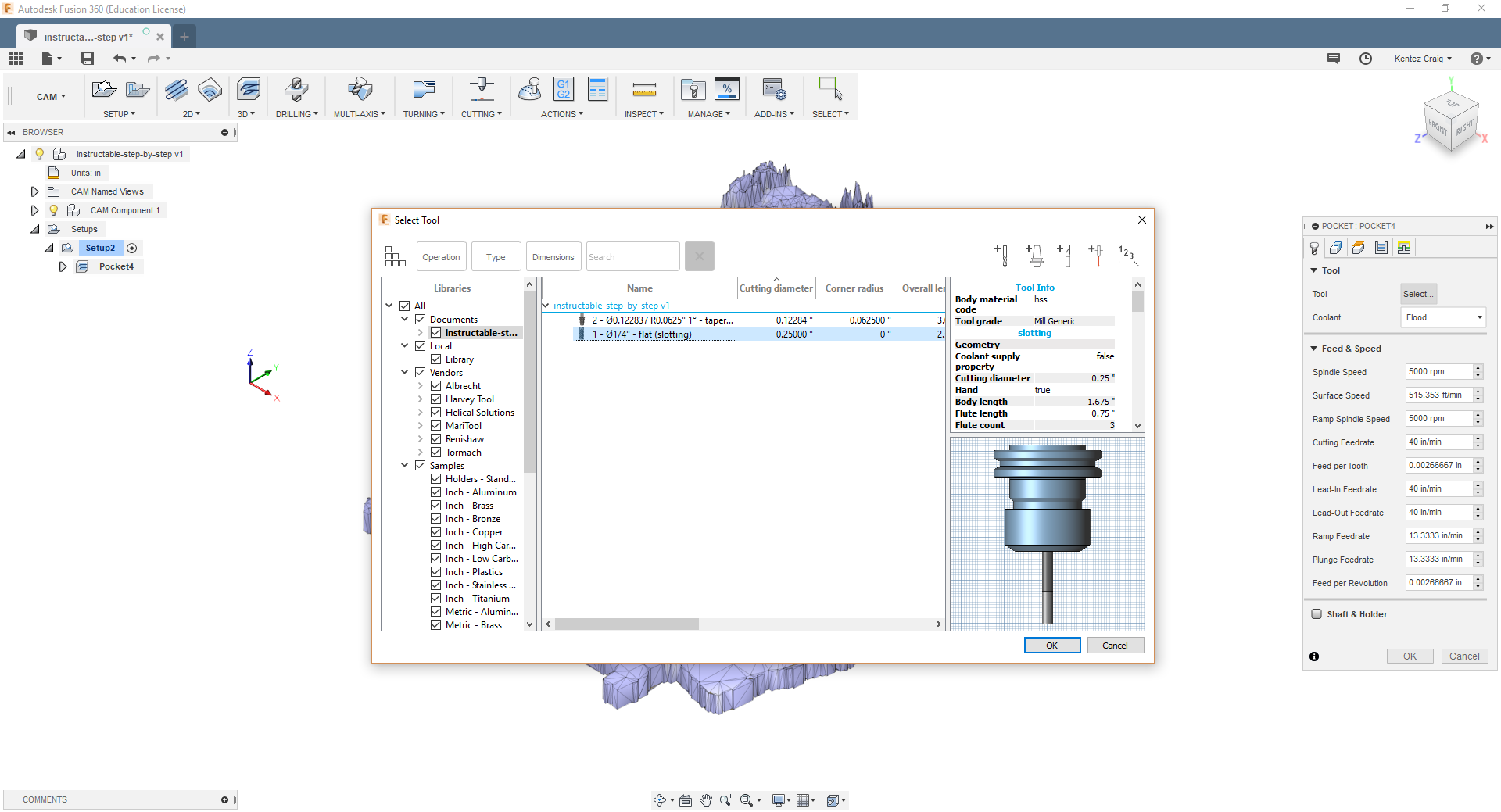
- Select 3D pocket from the dropdown at the top of the screen
- In the Tool tab: Select the .25 end mill from the tool library. Review the feeds and speeds as given. I try to ensure the Feed per Tooth stays less than 0.004 to prolong tool life and avoid crashing the CNC and breaking bits. Verify the settings are similar to what you see in the included photo. Feel free to change them around if you would like to experiment. These settings worked well for machining Walnut.
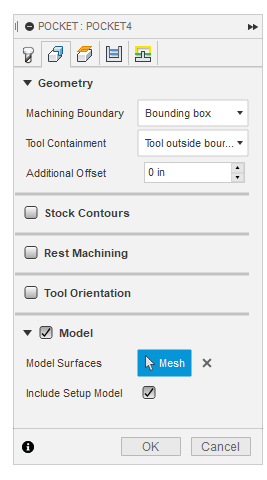
- In the Geometry Tab: Change "Tool Containment" to Tool outside boundary. This will ensure as many of the edges as possible are cleaned up by the roughing pass. Then select the radio button next to model. Select " Model Surfaces" as you did earlier in the setup.
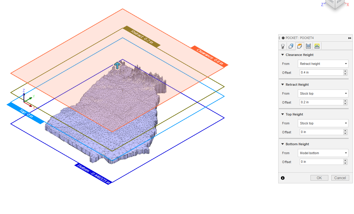
- In the Heights Tab: Ensure Top Height is set to the Stock Top,and the Bottom Height is set to the model bottom. Then glance over the Retract and Clearance Heights to make sure Retract is higher than Top and Clearance is higher than retract.
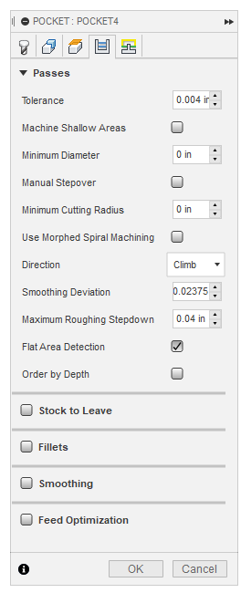
- In the Passes Tab: Check that the direction is Climb and the maximum roughing stepdown is 0.04 or less. Make sure none of the radio boxes are selected.
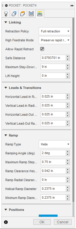
- In the Linking Tab: Check that your "Ramp Type" is a Helix and the "Ramping Angle (deg)" is 2 deg. Change your "Maximum Stay-Down Distance" to be larger than your part. This is done to save time as at this scale heat buildup on the cutting tool is not as much of a factor as it would be on a larger part.
- Click OK and you should see lots of blue tool path lines come up and a time appear next to the process indicating the cycle time for this step.
- Generate Vertical Parallel Pass:
- Here we will be following the same general procedure as used for the roughing pass. This time however, under the 3D dropdown menu we will select Parallel.
- In the Tool Tab: Select the .123 in tapered end mill and review the settings as given in the photo.
- Proceed through the rest of the tabs following the included photos.
- Generate Horizontal Parallel Pass:
- Right click the Vertical pass you just made and select "Duplicate" or press Control + D
- The tool path that has been duplicated is the one we will edit to make a horizontal path.
- The only change necessary is to alter the "Pass Direction" under the Passes tab when editing this tool path.
- The pass direction for the Horizontal pass should read 0 deg.
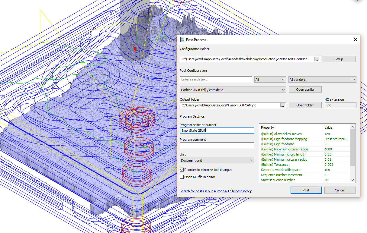
- Post Process:
- Next to the simulate tab select "Post Process" and search for Carbide in the preinstalled post processor files.
- The file extension will be listed as .nc.
- The photo included above is an example for the .25 in bit.
- All other tool paths follow this same procedure.
- As a point of note I have found that the best results come from exporting each tool path individually even if they use the same tool. This may be a result of our machine or our setup but this method produced the most consistent and repeatable results.
- You should end up with a total of three files.
- A .25in roughing
- A Vertical parallel with the taper
- A Horizontal parallel with the taper
Downloads
Fixture Wood
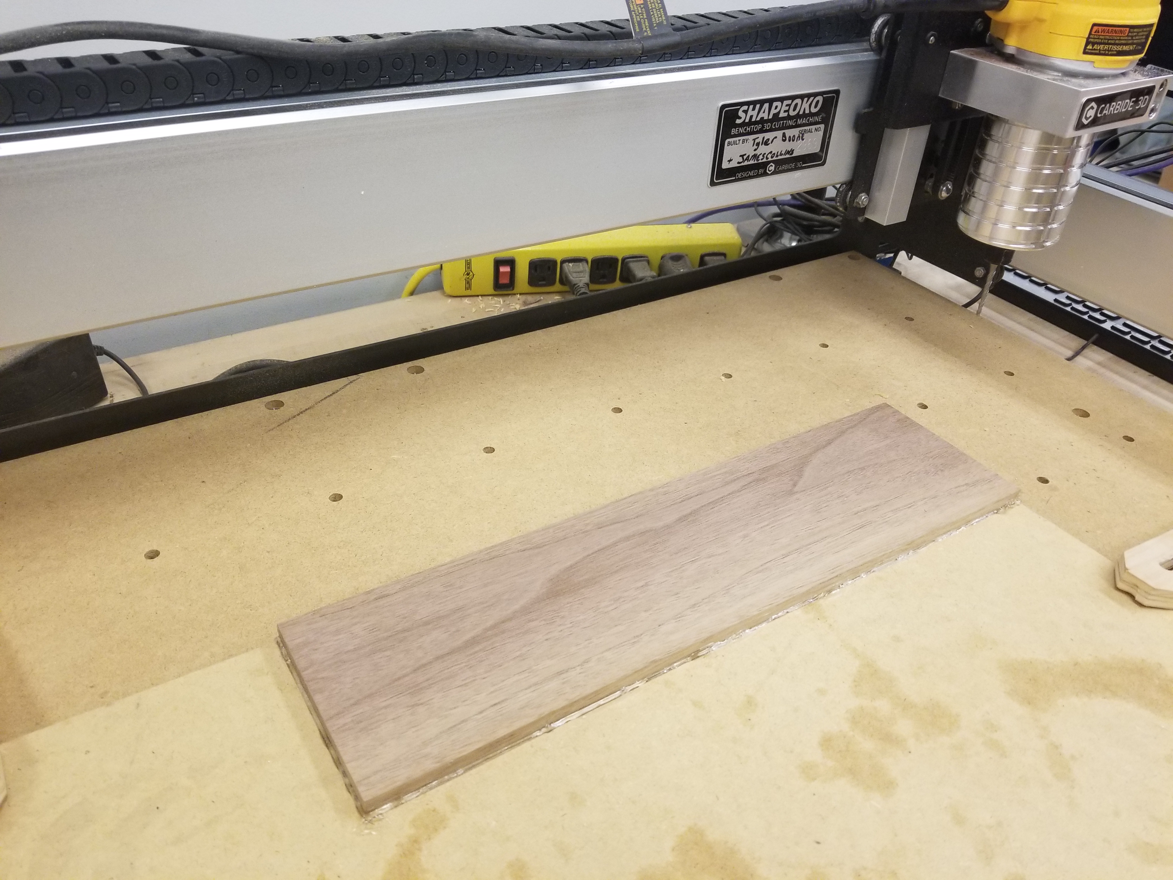
Marking the work area:
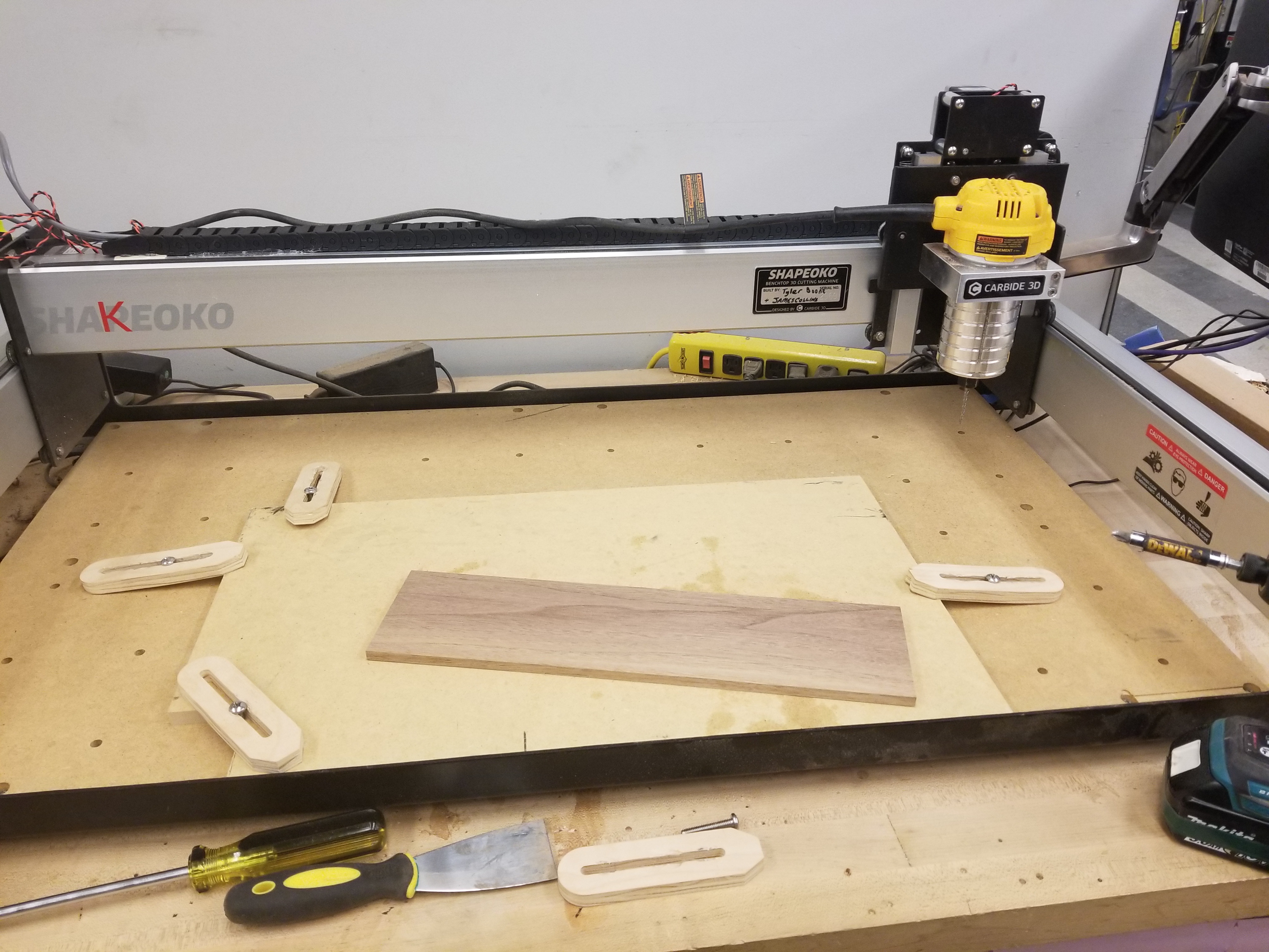
- Lay the stock over the MDF spoil board to be used in this project.
- Align the stock with a flat edge of the spoil board to help ensure it is oriented in the machines axis directions.
- Trace the edges of the stock with a pencil leaving the markings on the spoil board.
Fixturing the stock to the spoil board:
- Clamp a piece of MDF in place using the fixture method appropriate for your machine (I used threaded inserts and wooden clamps secured with Phillips head machine screws).
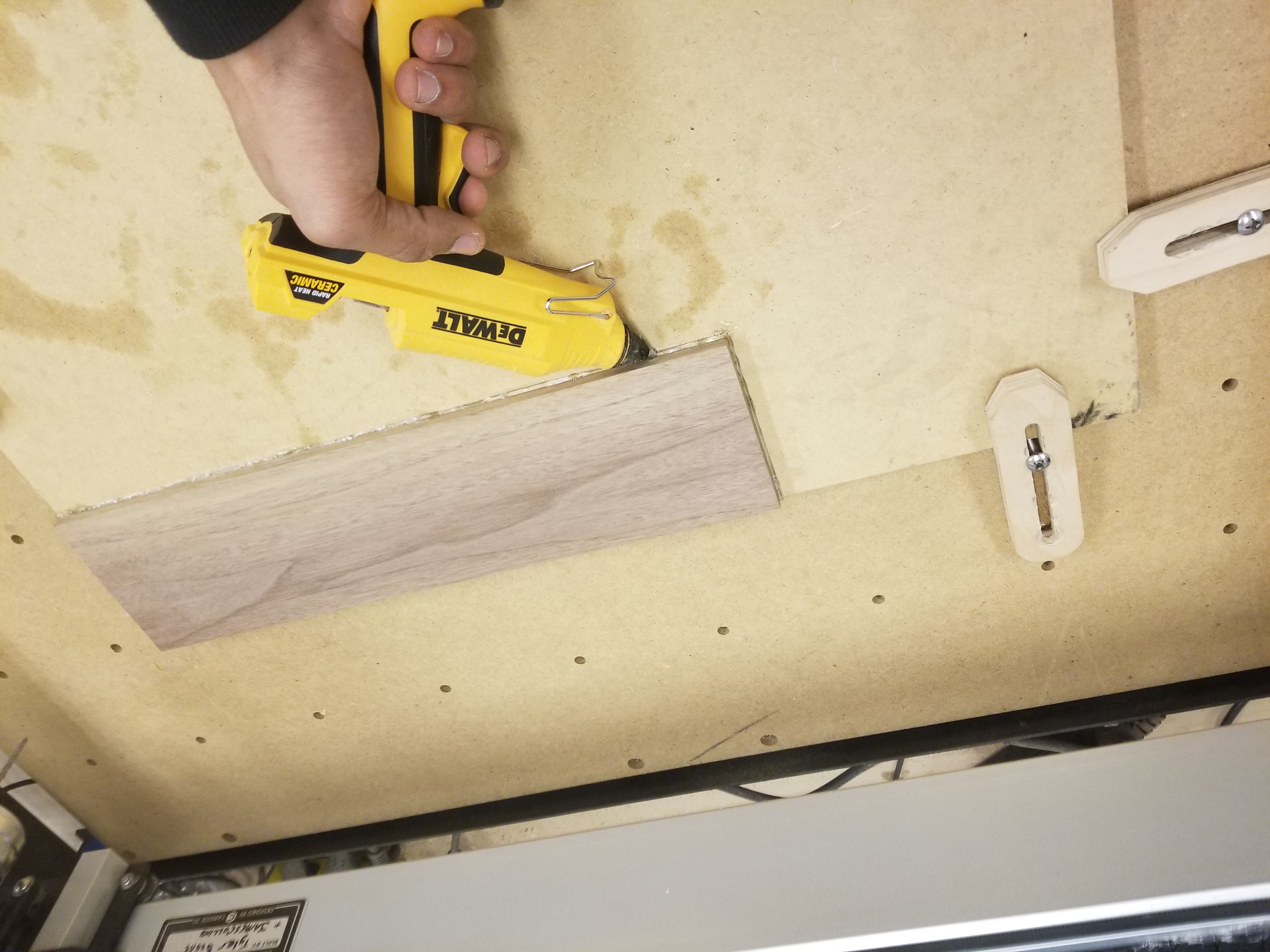
- Plug up the hot glue gun and allow it to heat to operating temperature.
- Using the hot glue gun quickly apply a thin and even layer of glue to the pre-marked work area.
- Press the stock in place firmly, taking caution not to get burned by glue that may escape the edges.
- Allow the glue holding the stock to cool.
- Once sufficient time has passed attempt to shake the fixtured stock. If the stock moves, remove it from the spoil board and clean off the glue. Then repeat steps 2-5 and reevaluate the adhesion.
- Once significant adhesion is achieved it is advisable to line the edges where the stock meets the spoil board with a line of hot glue to further support the stability during the machining process.
Turn on and Home Shapeoko.
- This process requires your Shapeoko to be setup with the limit switches with homing enabled in Carbide Motion as detailed here and here.
- With the Shapeoko motion control powered on, click the jog tab in Carbide Motion and click the words that appear saying begin homing.
- Allow the process to complete and then it will be time to upload the GCode!
Load Up GCode and Install the First Bit
- Insert your flash drive loaded with the post processed CAM we created earlier.
- Select the Load tab in Carbide Motion and select your first file from the popup window.
- Use a 17mm wrench and the spindle brake, (with the Dewalt DWP611 router) to install the .25 in collet with the .25 in bit set to the depth where less than .125 of the tool shank is showing while avoiding clamping on the flutes.
Set Zeros to Stock Size (X,Y,Z)
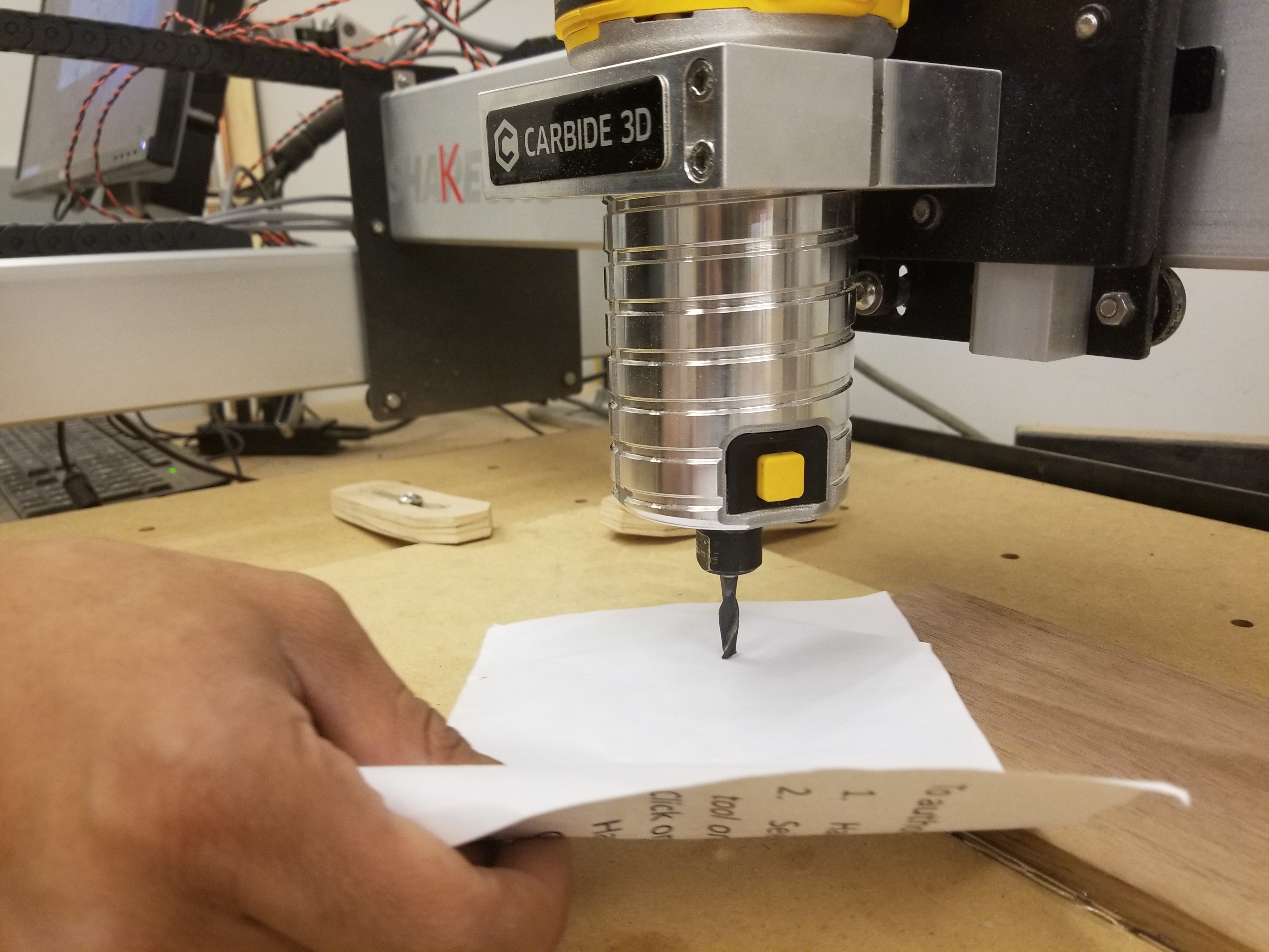
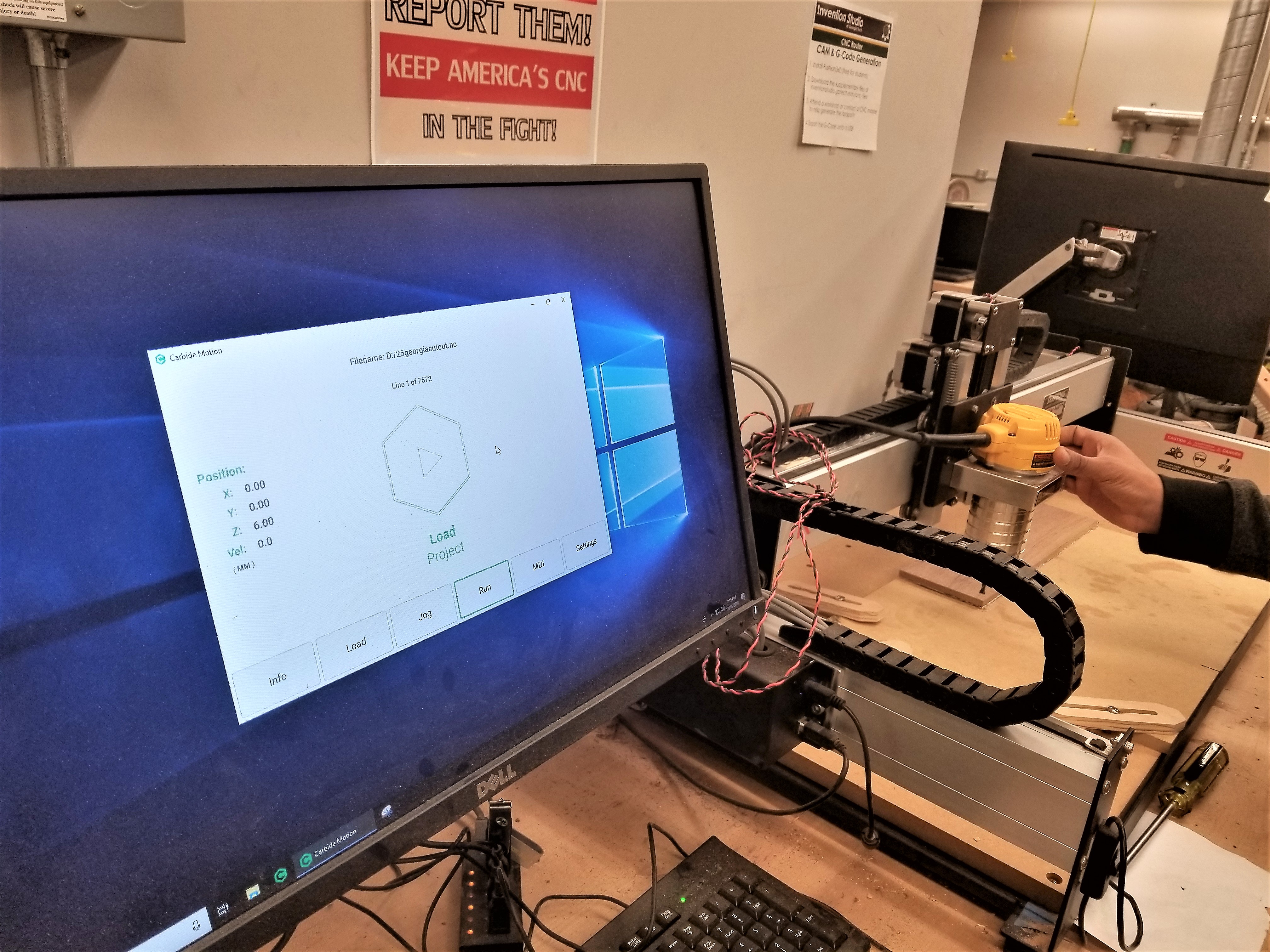.jpg)
- Set your XY position by using the arrow keys on your keyboard to jog the machine to the origin of the part you set in the CAM step. I like to use the lower left corner as it provides a standard from which to align stock.
- As you get close to the part to attain a higher degree of accuracy it is advisable to slow the traverse speed to allow for precise positioning.
- Once you reach the desired origin location select the set zero option and click the Zero X and Zero Y options.
- Setting the Z offset is done in a common manner to the XY mentioned previously. This time however we will desire a greater accuracy as this will determine how close to our design our result will be.
- Start by traversing the Z downwards over the stock with the on screen buttons.
- Once the bit is within approximately .125 in of the surface of the stock change your traverse speed to 1mm. and slide a single piece of copy paper under the bit.
- With the copy paper in place begin sliding it back and forth in the XY plane as you step down the Z by 0.1 mm or 0.01 mm (typically 0.1 mm is sufficient).
- Once the paper stops moving, stop moving the machine and reset the zero offset for the Z axis in Carbide Motion.
Run Roughing Pass
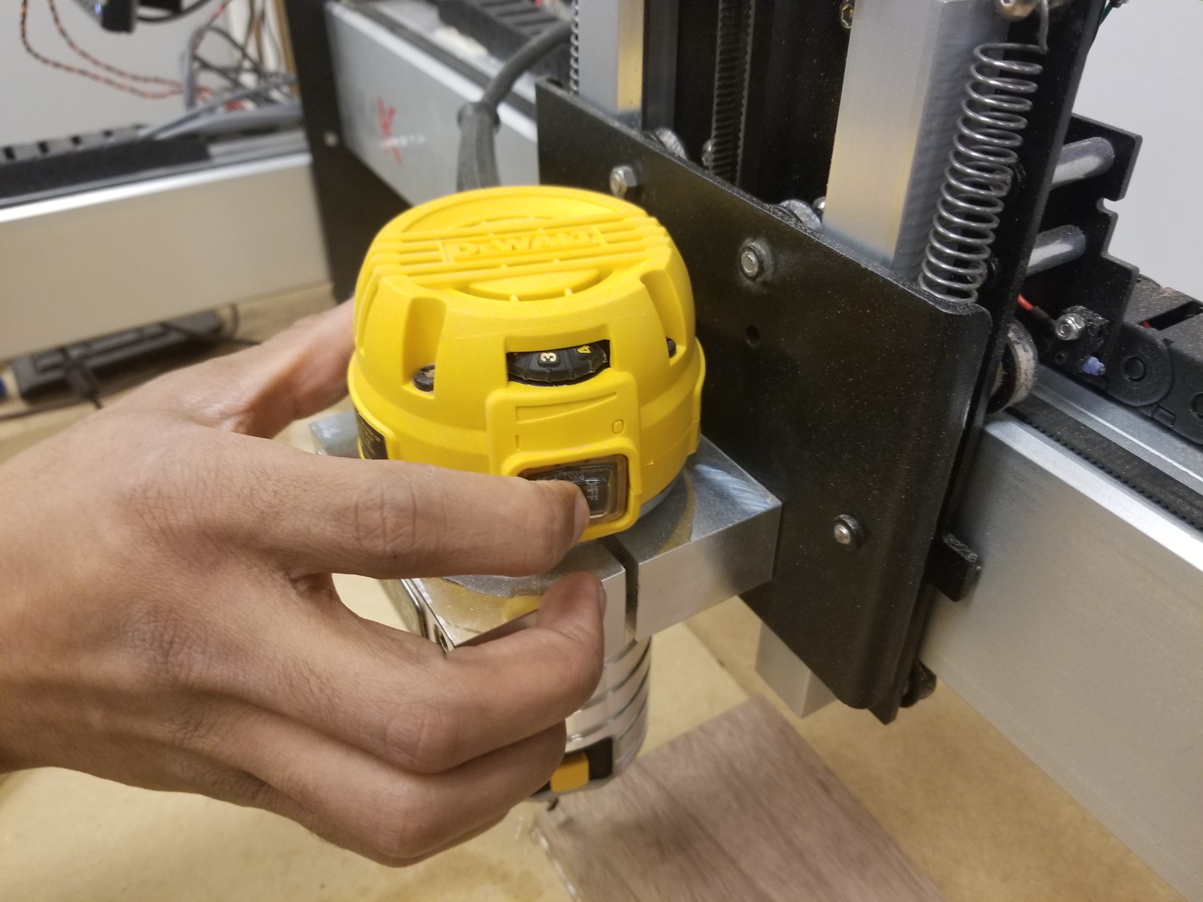
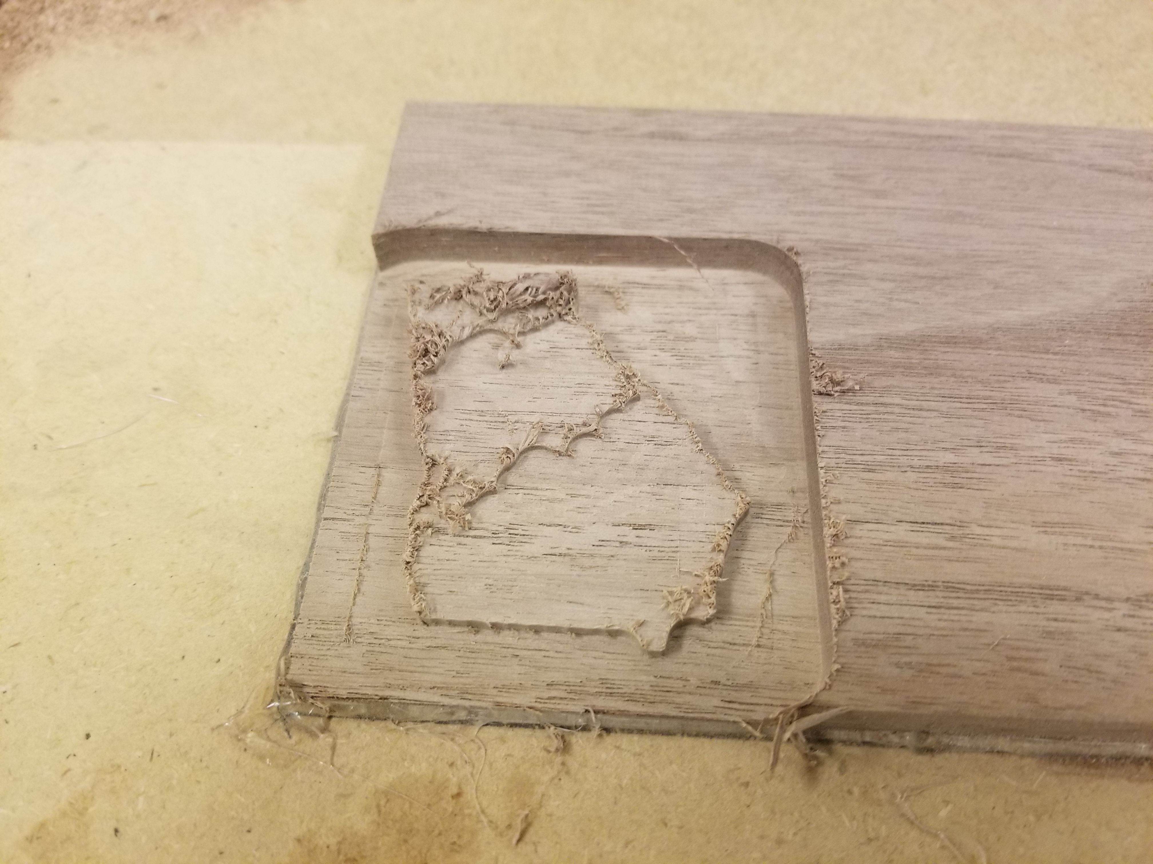
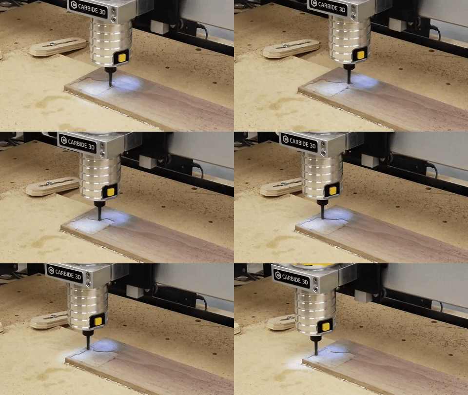
To run the roughing pass:
- Ensure the 0.25 in bit is installed and tightened.
- Verify the home is set to the intended location on the stock by traversing there using the Current offset XY button and the Z + 6 mm button in the Rapid Positioning menu.
- Once the home is verified, select Begin Project under the Run tab of Carbide Motion.
- When asked to install the cutter, take one last chance to verify the correct cutter is installed and tightened then turn on the router to the desired speed.
- Acknowledge that the bit is correct and allow the cut to begin.
- Monitor the cut and turn off the router upon completion.
Switch Out Bit and Rehome Z.
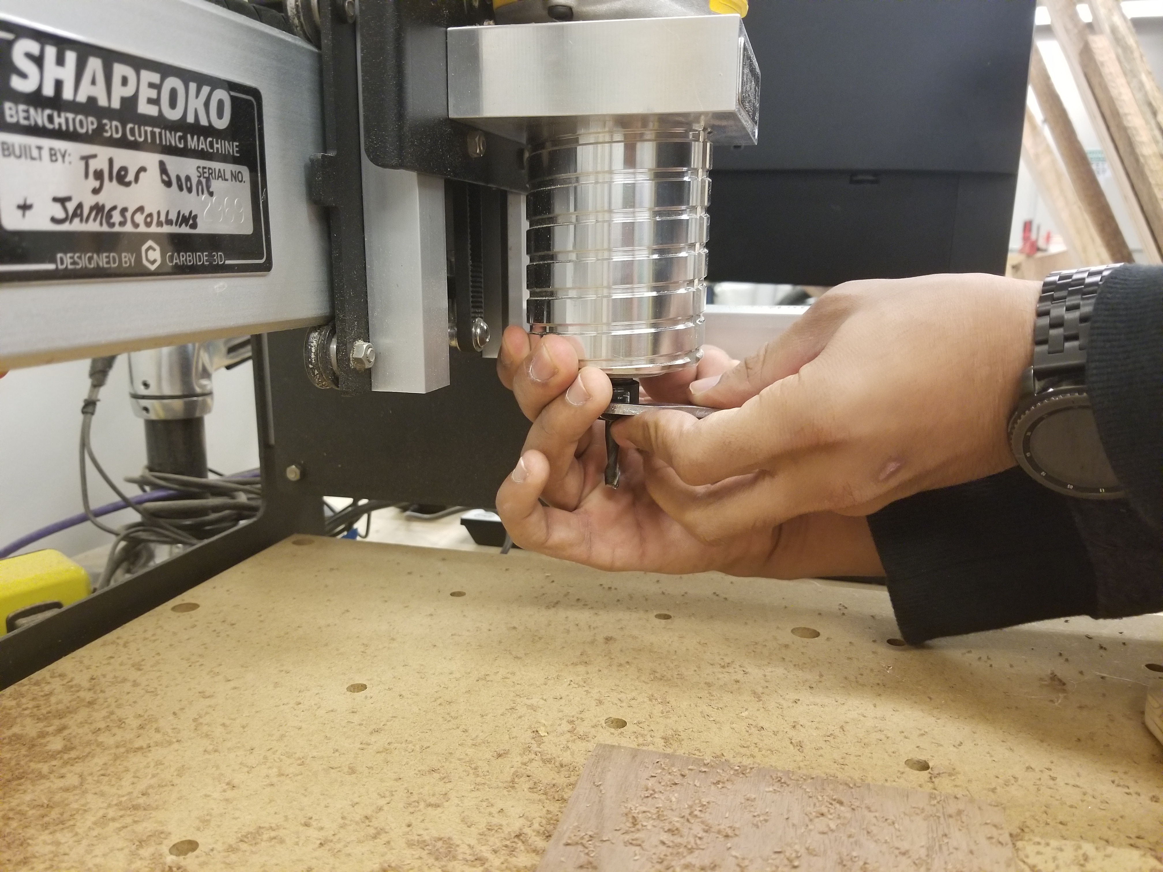
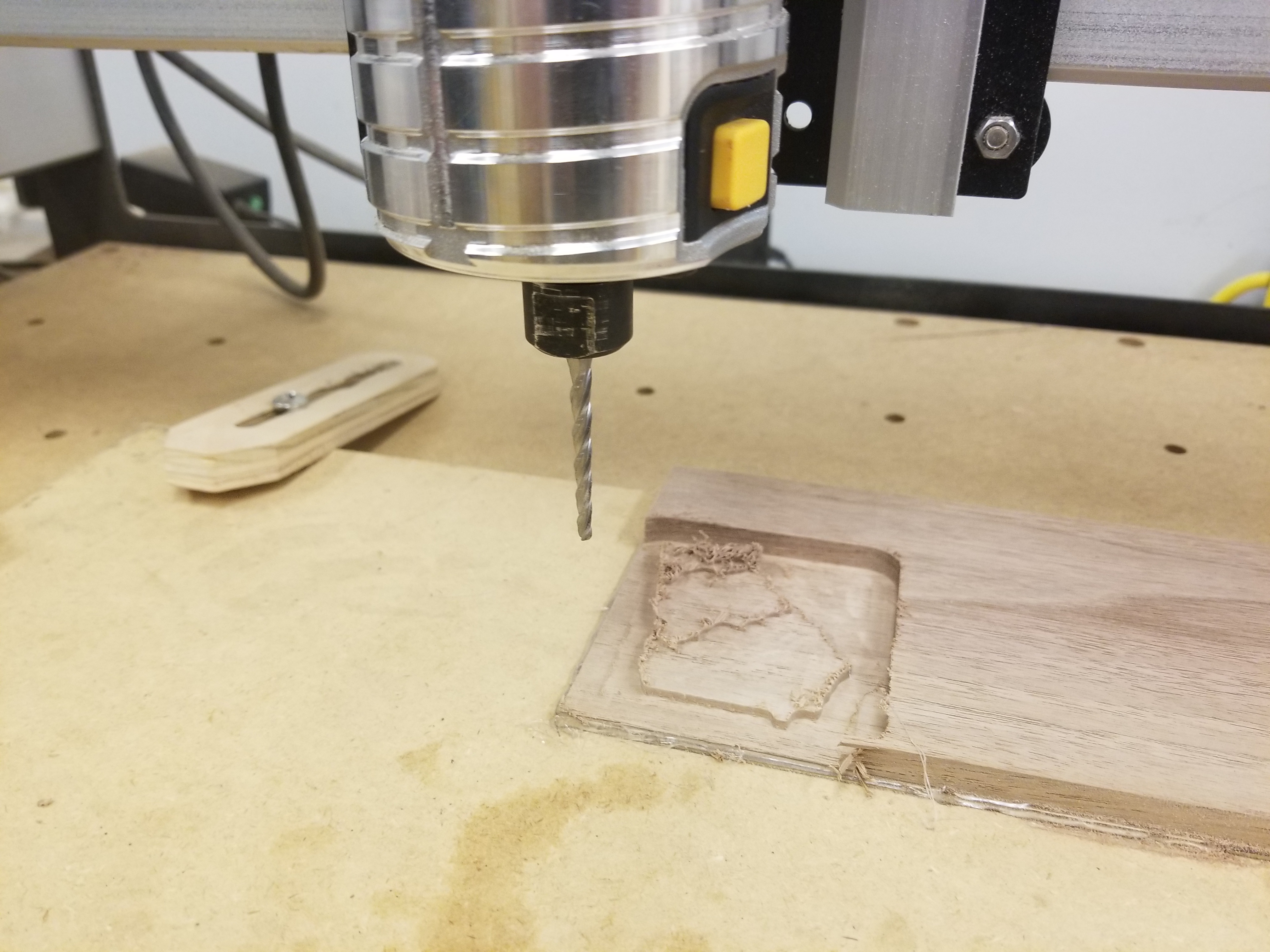
- Once the router is safely powered off, you may use the same 17 mm wrench and spindle brake on the router to loosen the collet.
- If you are unable to remove the bit due to the lack of clearance between the bit and work material you may power down the motion control of the router and gently move the gantry system to a location in the work space where there is greater room to allow for the changing of bits.
- Once the collet is loosened carefully slide out the .25 in end mill.
- Next seat the .125 tapered ball end mill into the collet ( A collet change is unnecessary as both tools have the same shank diameter ) and tighten the collet finger tight so that the bit does not fall out.
- Tighten the collet using the same procedure mentioned previously with the 17 mm wrench and spindle brake.
- Check to make sure less than .125 in of the tool shank is exposed yet the collet is not clamping onto the tool flutes.
- With the new tool installed power on only the motion control for the Shapeoko. Then, close and re open Carbide Motion and reconnect the cutter.
- With the cutter reconnected, click the jog tab and click to allow the homing routine to run to completion.
- Next click the Rapid Position button and select current offset XY.
- This step will bring the cutter over the home position set for all the tool paths.
- Jog the machine over the closest non machined area of the stock.
- Repeat the steps mentioned for homing the Z axis as discussed for the .25 in cutter.
Run Vertical Pass
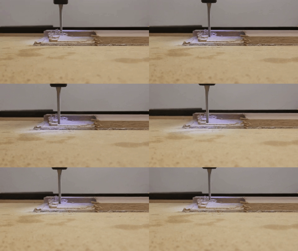
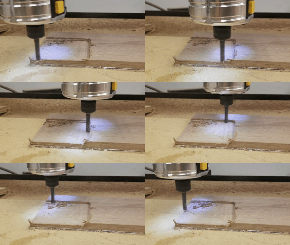
(gif)
- With the taper bit installed, under the Rapid Position tab select both Current Offset XY and Current Offset Z+6 mm.
- Inspect the positioning to reconfirm that the Z axis zero was properly reset for the new tool.
- Click the Load tab in Carbide Motion
- Select the file prepared earlier for the vertical pass with the taper bit.
- Confirm the file name matches the file name you selected for the vertical taper pass
- Select Run in Carbide Motion
-
When asked to install the cutter, take one last chance to verify the correct cutter is installed and tightened then turn on the router to the desired speed.
-
Acknowledge that the bit is correct and allow the cut to begin.
-
Monitor the cut and turn off the router upon completion.
Run Horizontal Pass
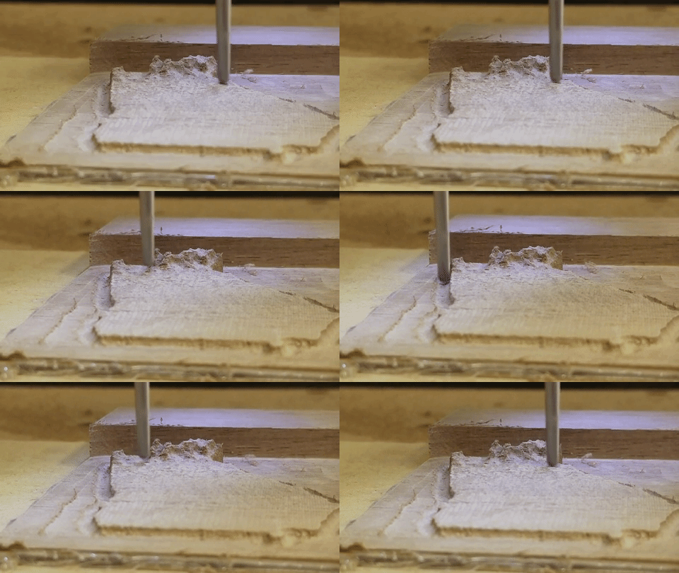
- Repeat all the steps mentioned for running the vertical pass.
- ENSURE THAT YOU REMEMBER TO CHANGE THE FILE UNDER THE LOAD TAB TO THE FILE PREPARED FOR THE HORIZONTAL PASS
Separate From Spoilboard
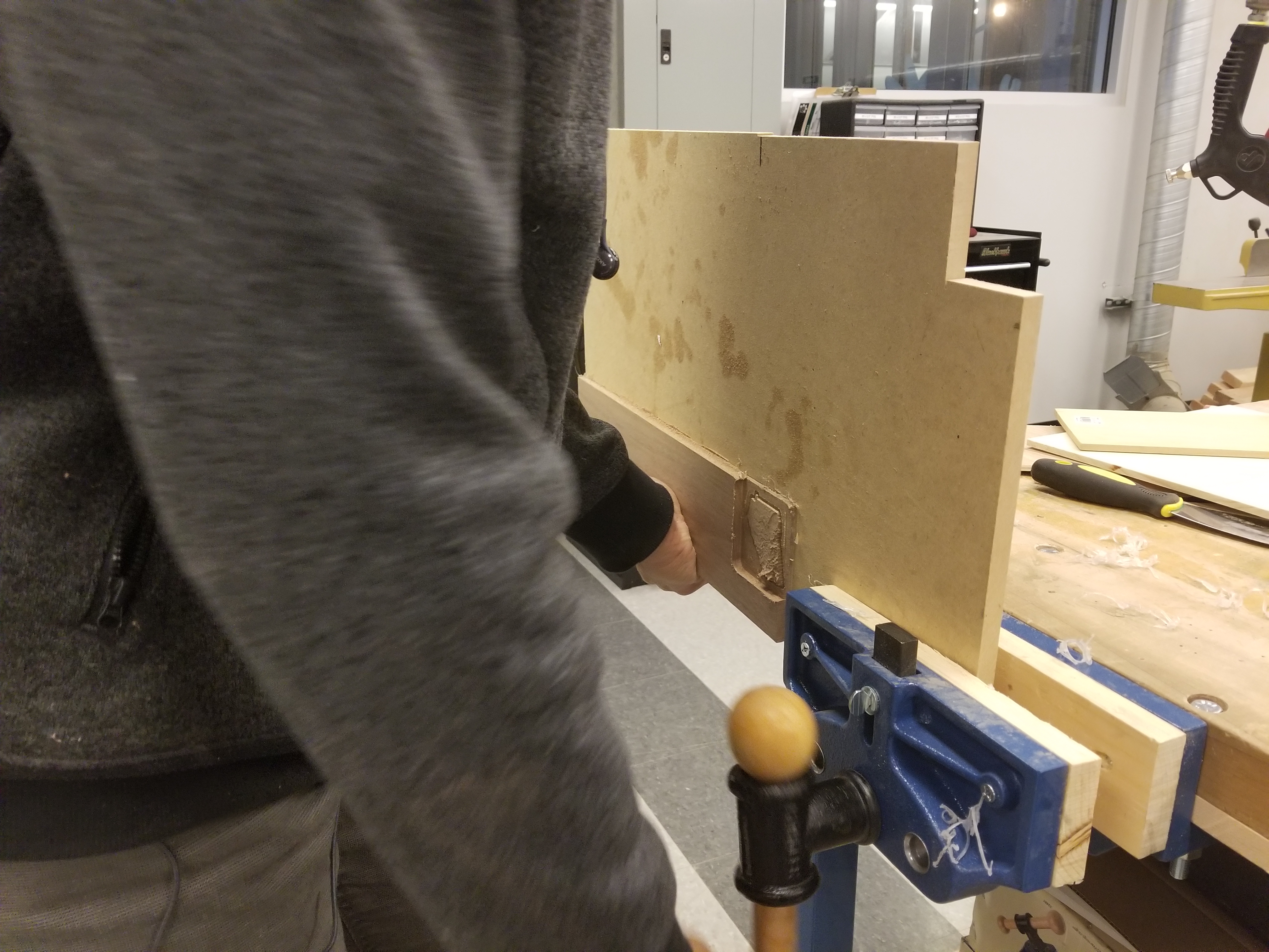
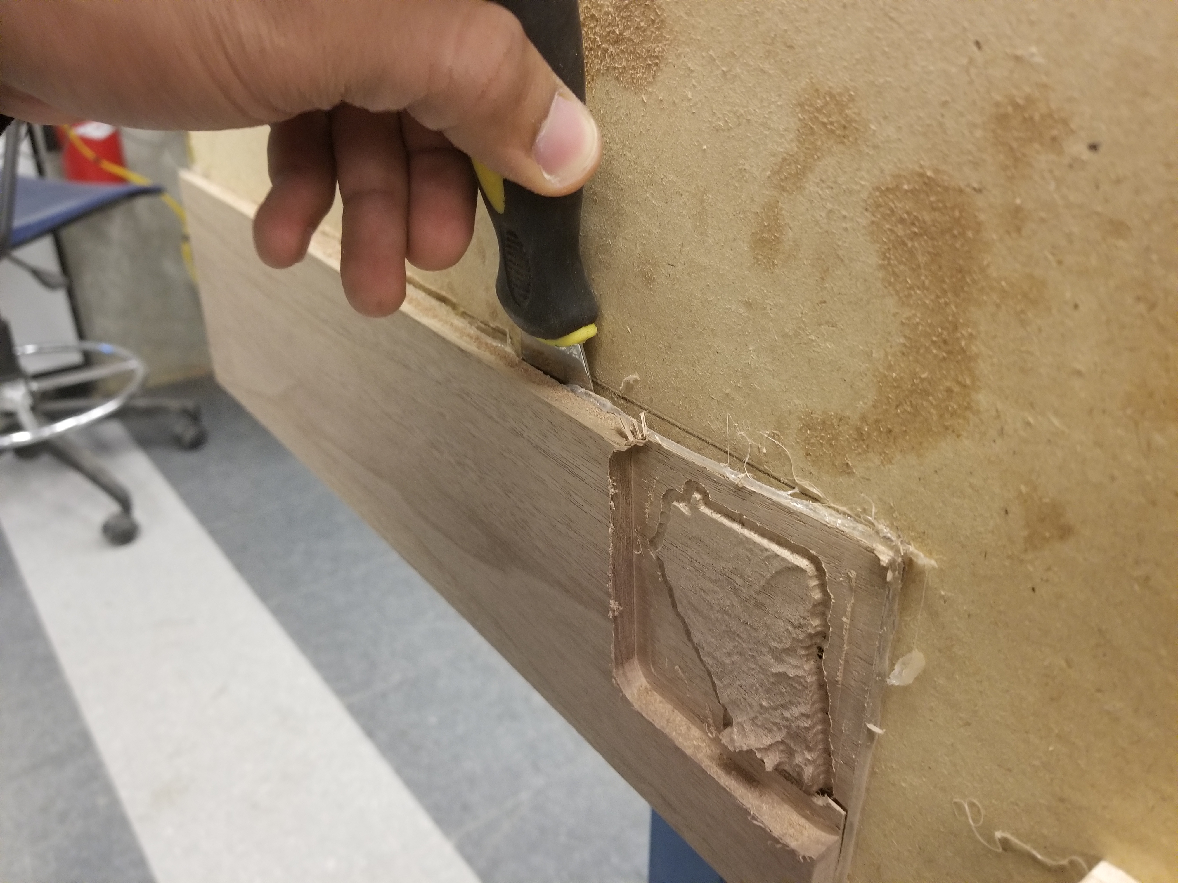
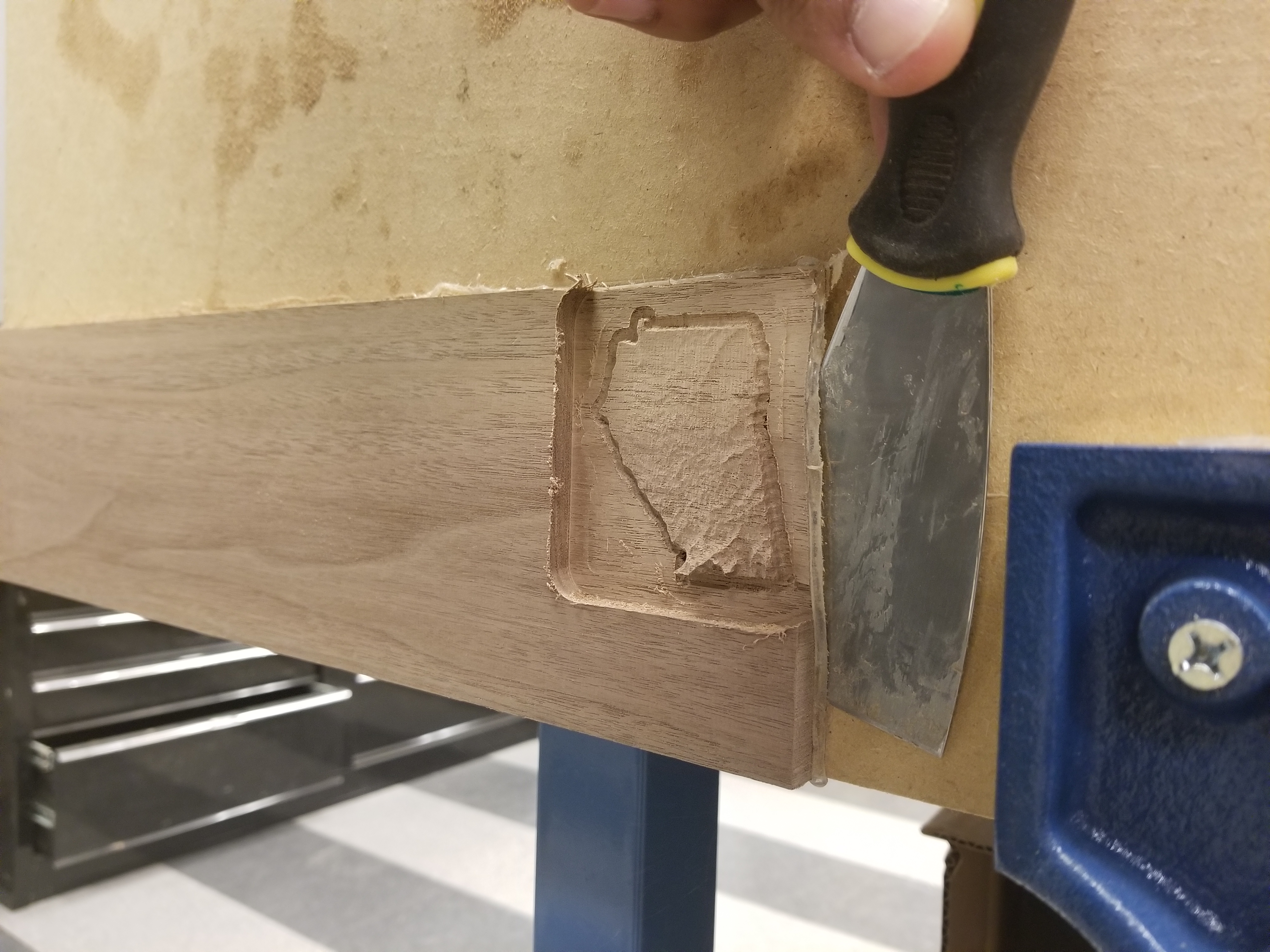
- After removing the spoil board and machined stock, securely clamp the spoil board in a vise.
- Once clamped, position the putty knife where it may slide between the machined stock and the spoil board with the help of a few gentle blows from a hammer.
- Gently begin tapping the back of the putty knife until it begins to pry the part away from the spoil board
- Continue this process by repeating step 3 in several different areas over the adhered section of the stock to prevent breakage of the parts from the prying action.
Break Off of Remaining Support.
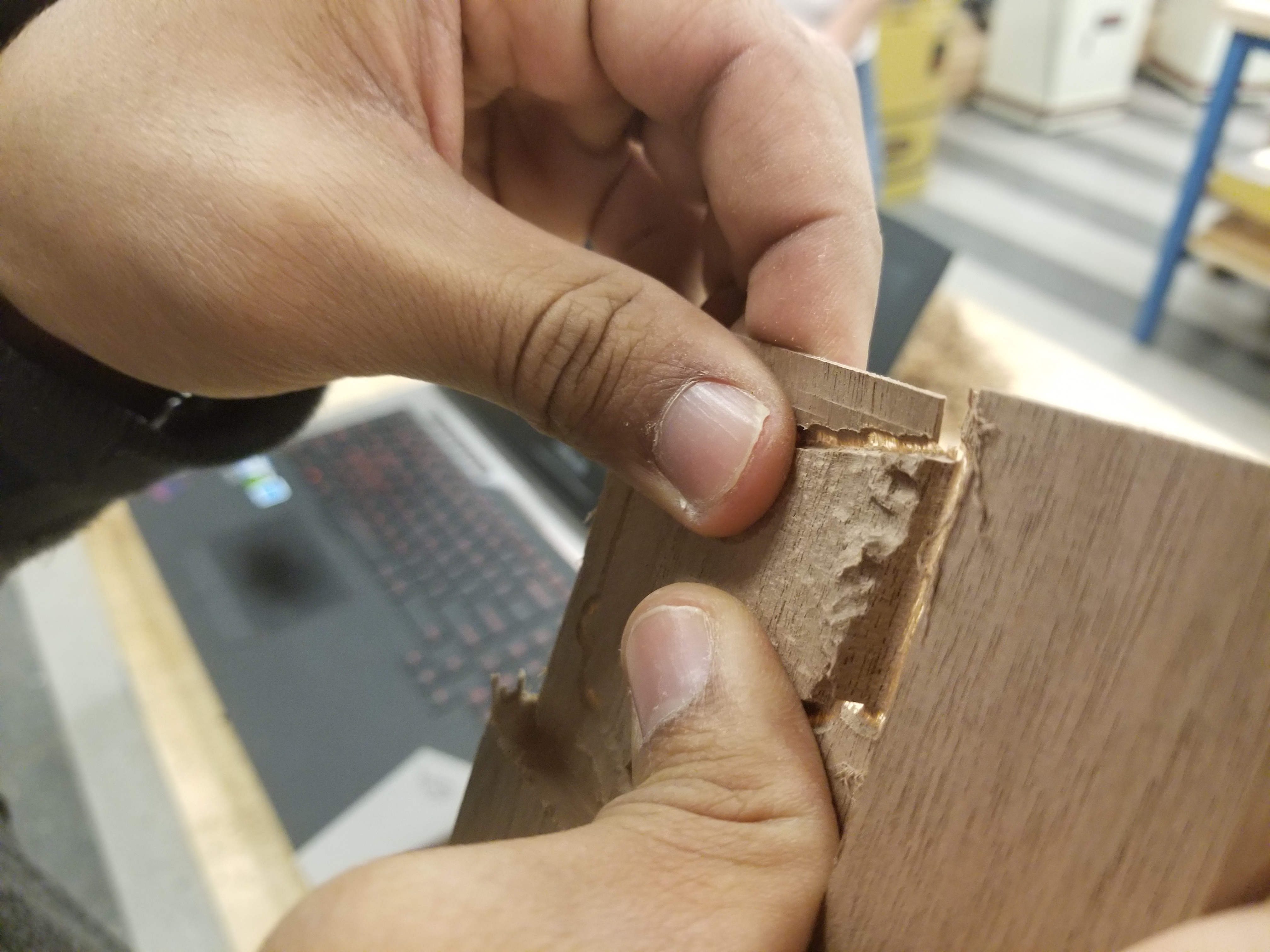
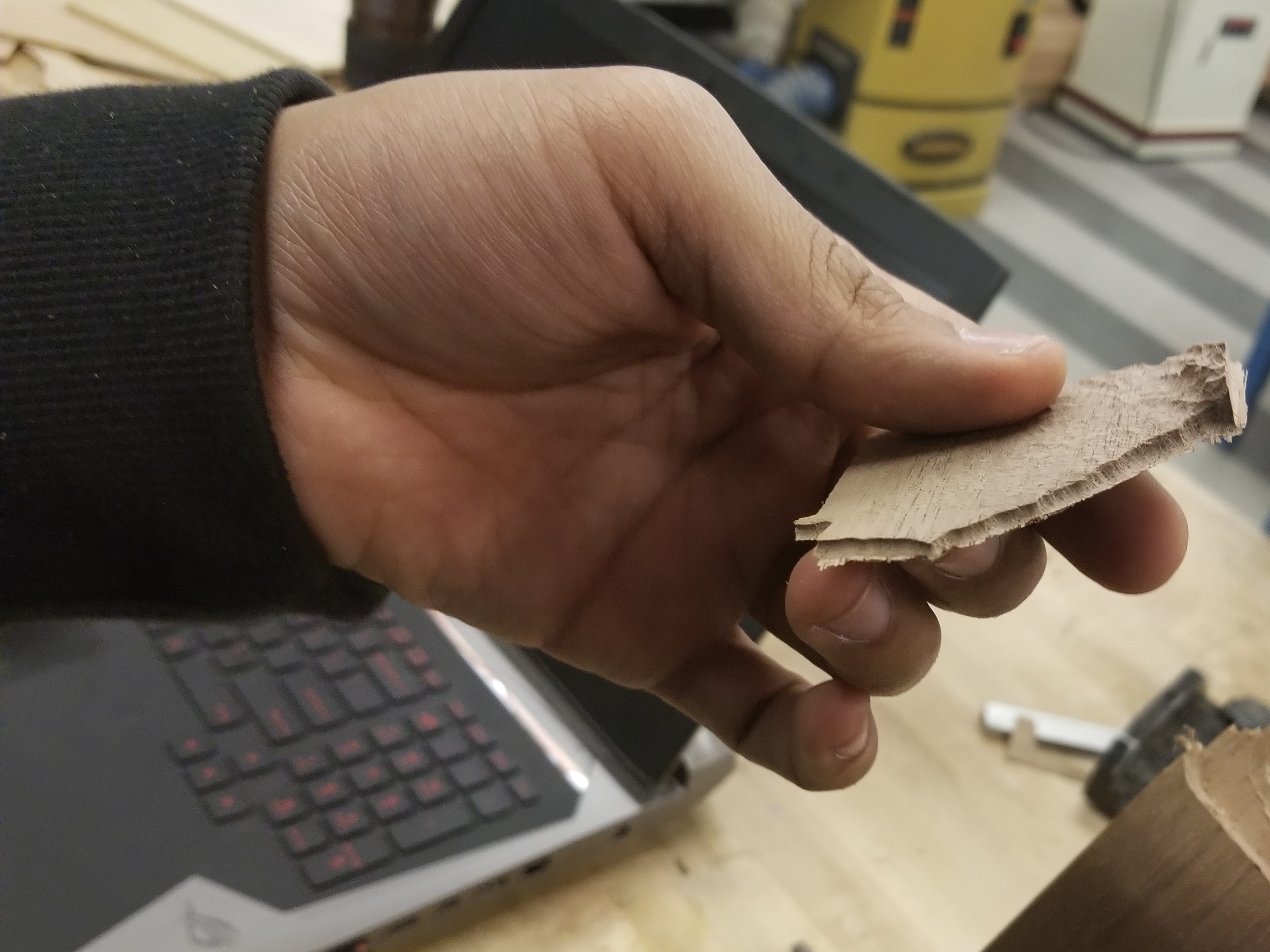.jpg)
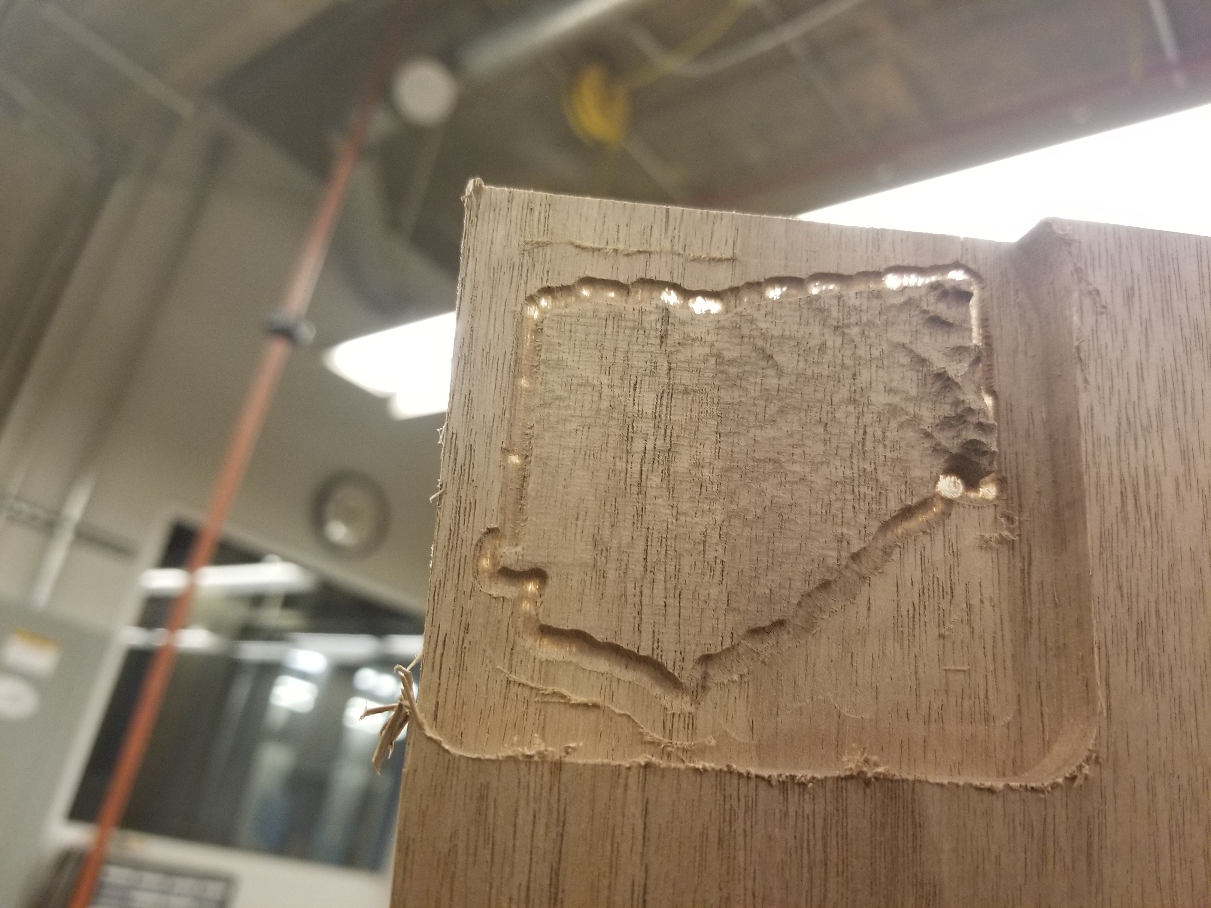
- If your stock size was set correctly in the CAM then the taper passes should have left the edges of the piece perforated.
- Using caution you may carefully break the machined part away from the rest of the wood taking care not to damage the part.
Sand Edges
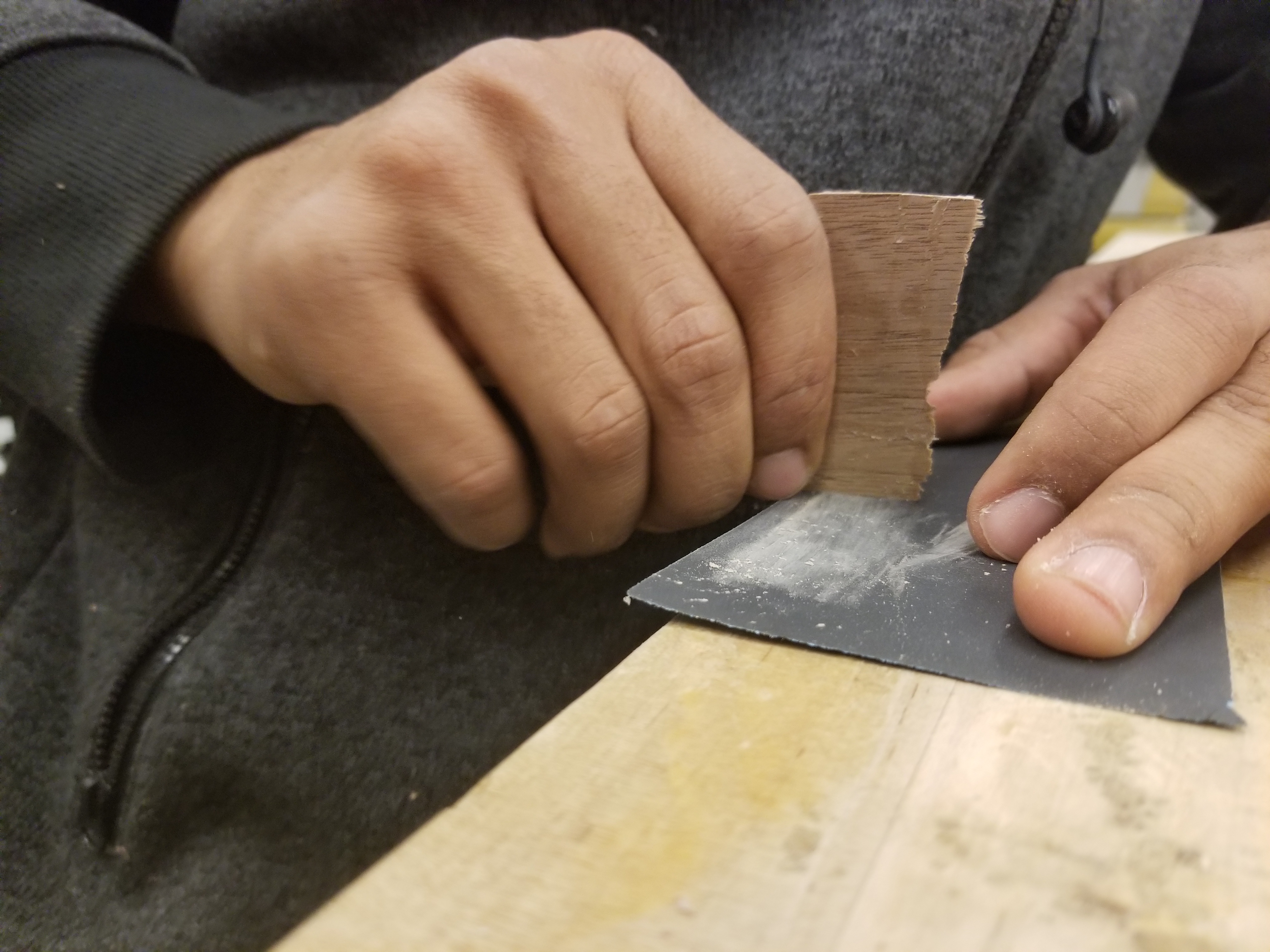
Using some 220 Grit sand paper carefully sand the edges down to the edge of the machined area.
Drill Pilot Hole and Place Eyebolt
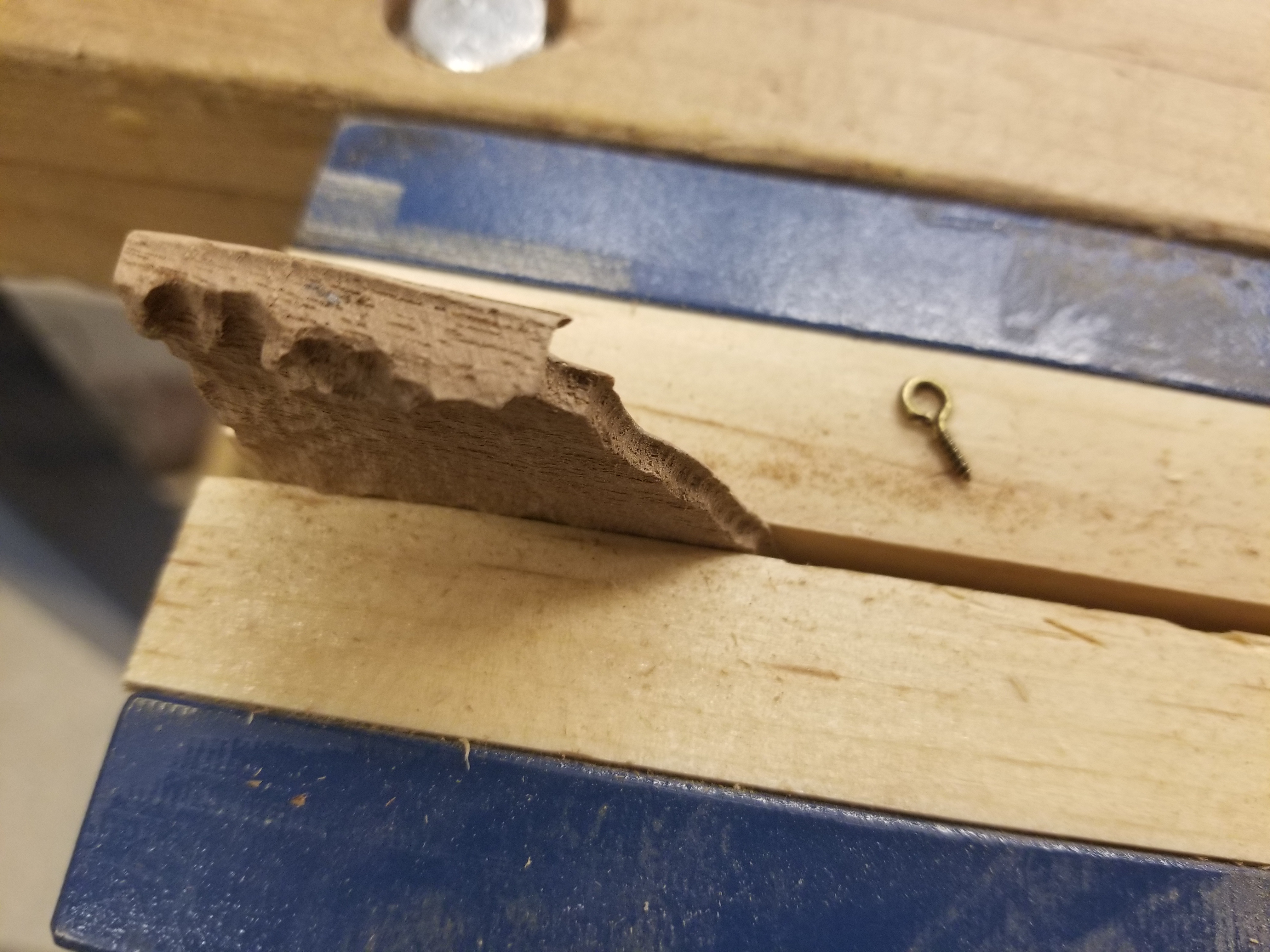
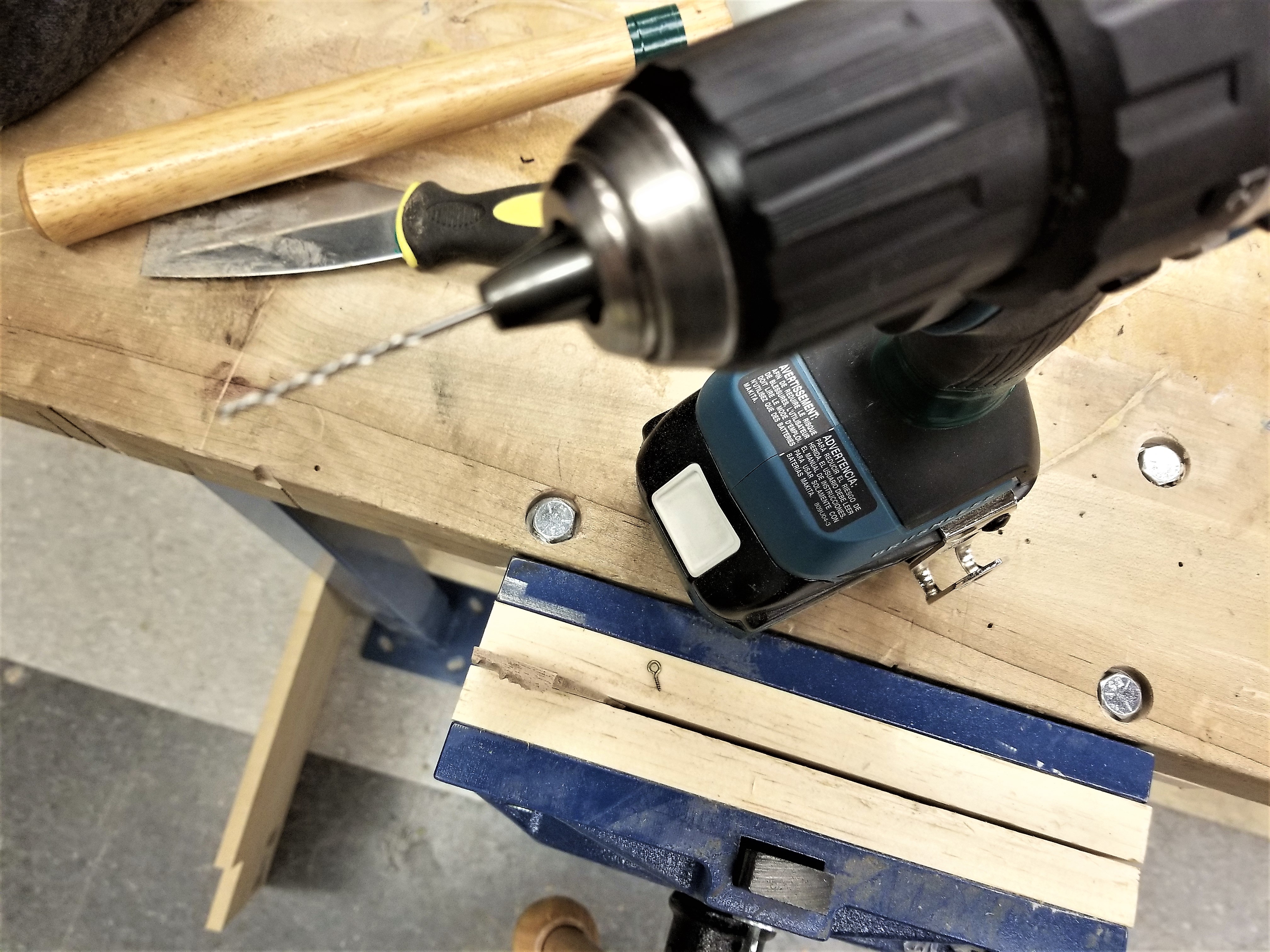.jpg)
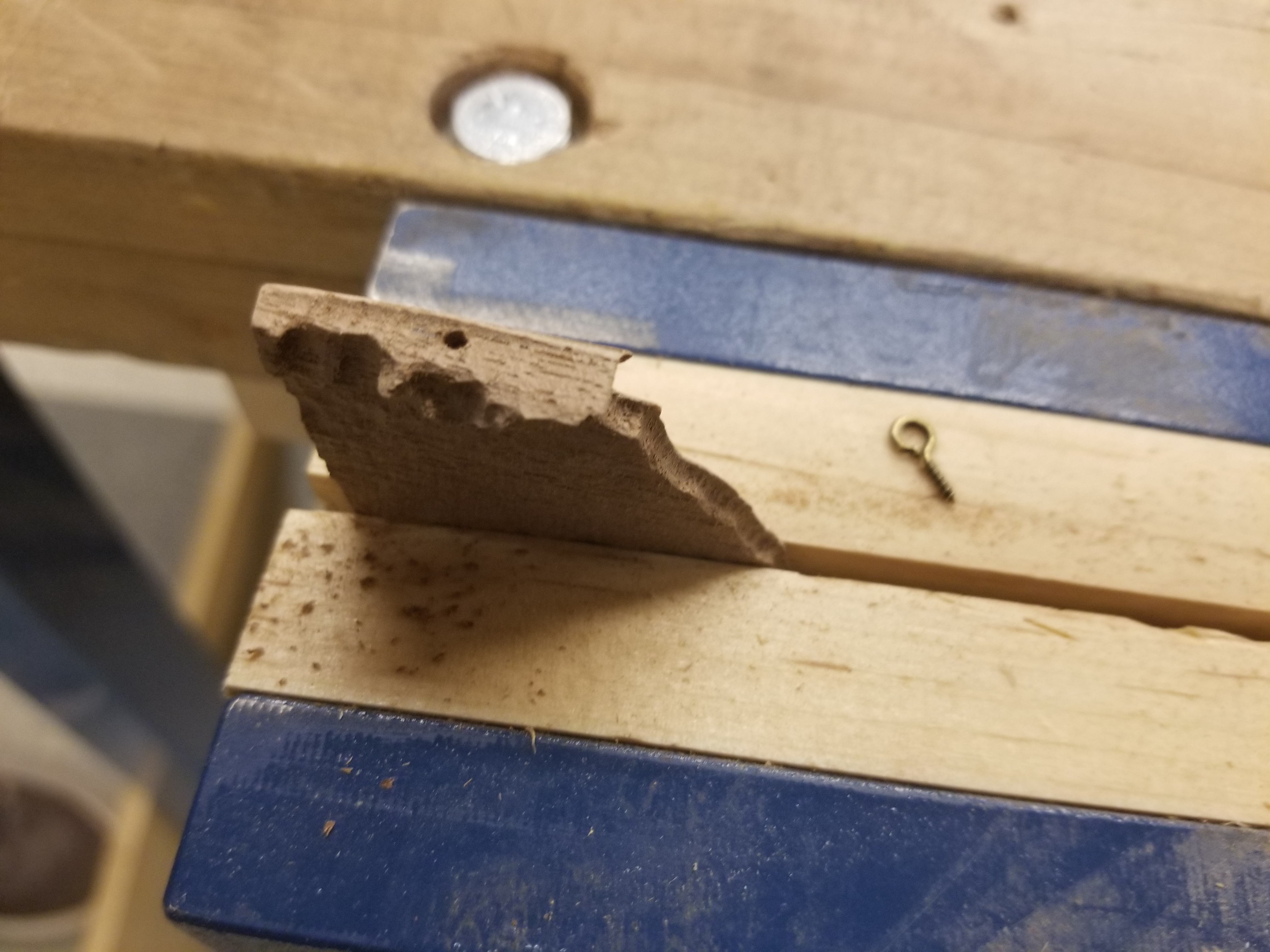
- Gently clamp the part with the top side up and exposed, taking care not to damage the surface while holding the part still.
- Tighten the appropriate sized drill bit for the size of your I hook into the chuck of the drill.
- Carefully drill a hole in the thicker area of the top of the state and screw the hook in place.
- Note: If you are concerned that screwing in the hook may damage the part you may instead drill a slightly larger hole to act as a clearance fit for the threaded portion of the hook. Then the hook can be secured in place with a tiny dab of hot glue. ( Careful not to burn your fingers! )
Apply Mineral Oil
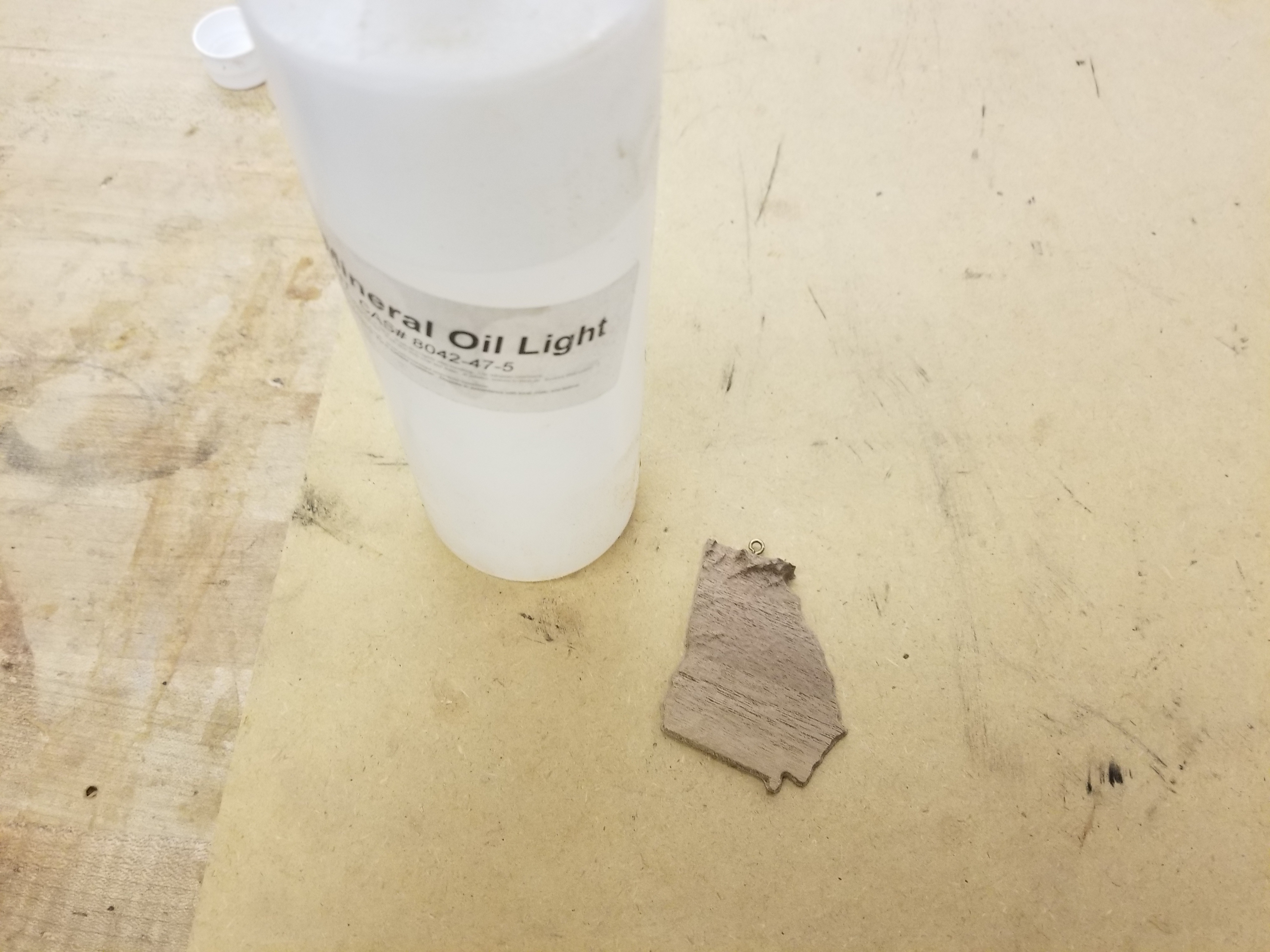
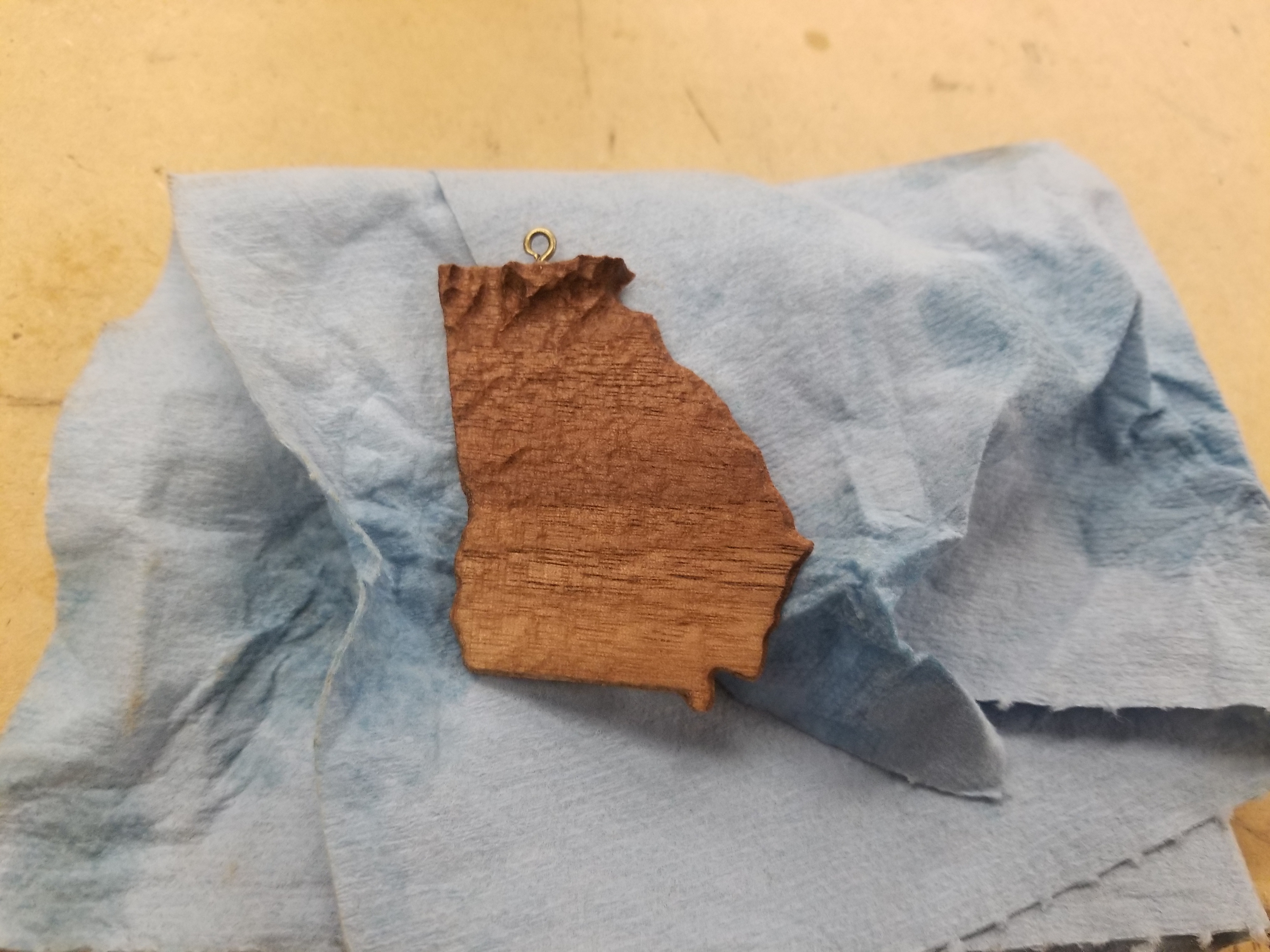
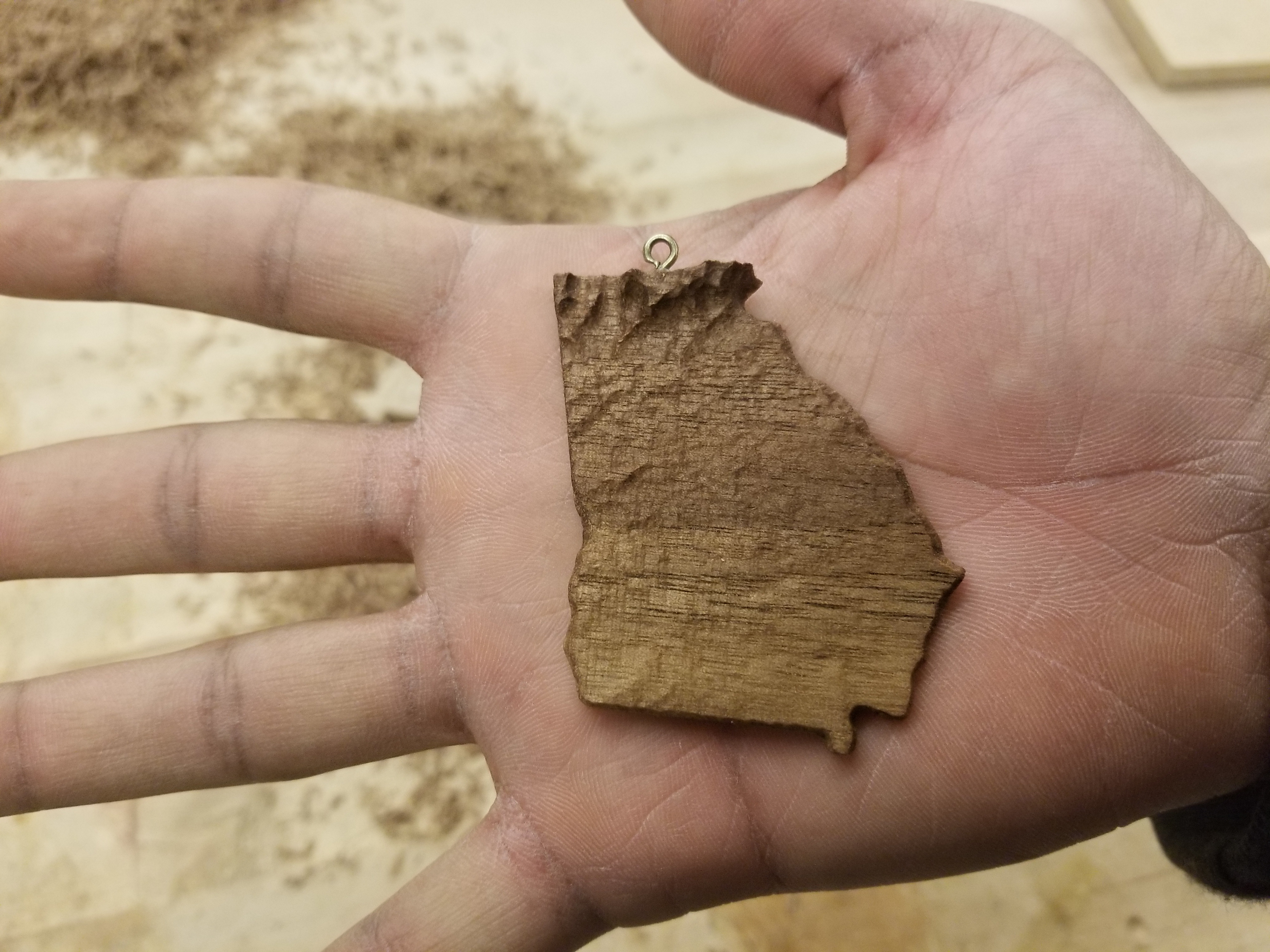
- Moisten one corner of a clean shop towel with mineral oil.
- Apply a coat to the piece by dabbing and gently wiping the moistened shop towel over all edges of the SMOL state.
- Once the coat looks even, allow it to dry and reapply if necessary.
Make a String Loop and Hang!
.jpg)