SImple Arduino Quadcopter
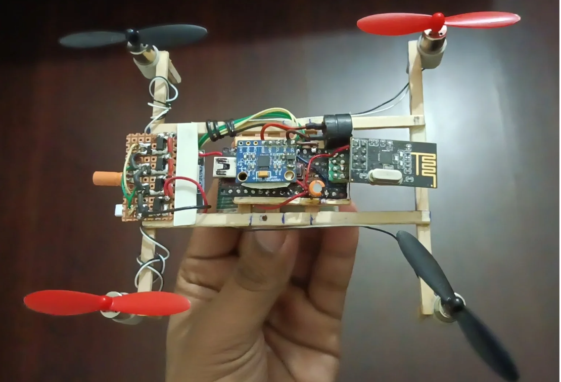
The allure of drones lies in their multifaceted applications.
Building your own drone from scratch not only enhances your understanding of aerodynamics and electronics but also offers unparalleled satisfaction.
In this Instructable, I’ll walk you through the creation of a custom fully Arduino-based MultiWii drone featuring an Arduino Nano, MPU6050 sensor, NRF24 module, custom motor driver board and a custom-built remote controller. With the combination of highspeed 8520 coreless motor with 55mm propellers and 650mah li-po battery powering this lightweight marvel, this project is an excellent foray into DIY small scale RC aircraft.
Supplies
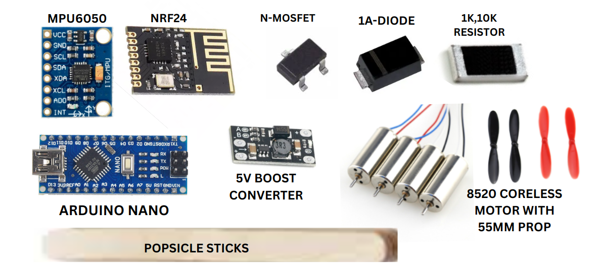
Components Used in the Build
- 1x Arduino Nano: This compact microcontroller serves as the brain of the drone, processing sensor data and controlling motor speeds.
- 1x MPU6050: A 6-axis gyroscope and accelerometer module that provides real-time orientation data, ensuring stable flight.
- 1x NRF24: A wireless transceiver module used for communication between the drone and the remote controller.
- Custom Motor Driver Board: This board has 4x n-channel power mosfet with 4xflyback diode and 4xpower limiting resistors for 4 motors with 4x capacitor at the end of each motor terminal to make them smooth. This board is designed to manage the power distribution to the four 8520 coreless motors, ensuring smooth and efficient operation.
- 650 mAh Battery: A lightweight power source that offers sufficient flight time for a mini drone.
- 8520 Coreless Motors with 55mm Propellers: These compact motors and propellers provide the thrust required for flight.
- Custom Remote Controller: Arduino based,designed with intuitive controls, this unit communicates with the drone via the NRF24 module.
Designing the Main Frame
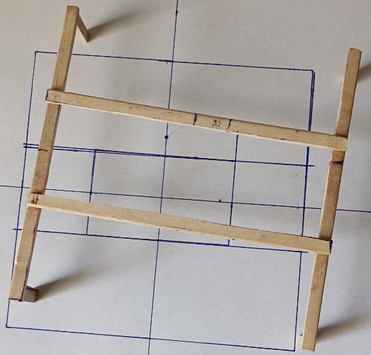
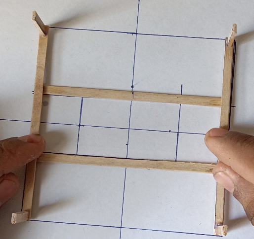
Let's begin with main frame for our drone. I used popsicle sticks due to thy are light weight and hard enough for our drone and also easily available in stores.
At first I have sliced the popsicle sticks in half then drew the simple fame and glued them in as per the design.
I have also attached some landing sticks.
Making Motor Holders
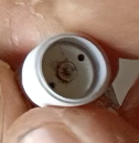
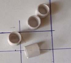
To hold the high highspeed coreless motors with our frame we have to make 4x motor holders which will help to adjust the motor positions and also replace them. Motor holders must be hard, tight enough to hold our motor with the frame and also light weight.
So, insted of finding on web I designed my own by cutting some paper strips, glued them in a circular structure with the help of an 8520 motor I got the perfect circular motor holder of my motor diameter. I designed 4 of them for 4 motors.
Adding Motor Holders to Frame
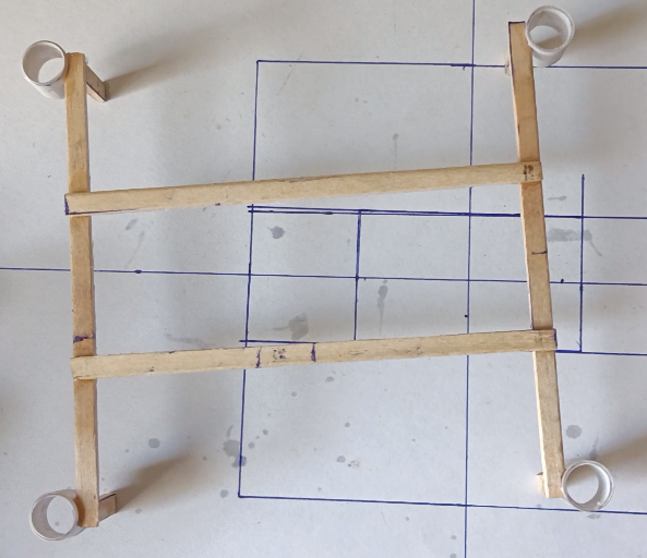
Now it's time to add motor holders to the frame. As in the Image I glued them on the frame. Make sure they are straight facing top, if any one of them is not straight will cause our drone unstable.
Inserting Motors to the Frame
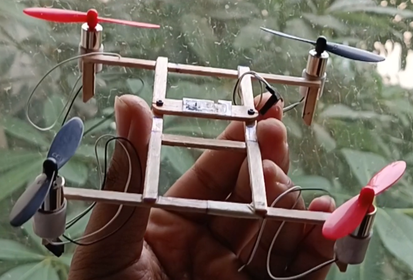
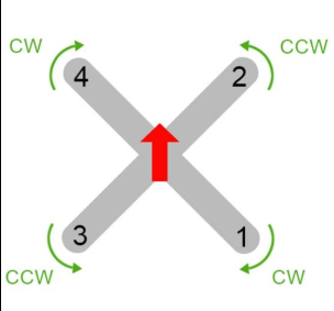
Now insert 4 of the coreless motors to the holders attached with the frame and make sure to add propellers 2 clockwise and 2 counter clockwise as in the image.
Flight Controller With Receiver
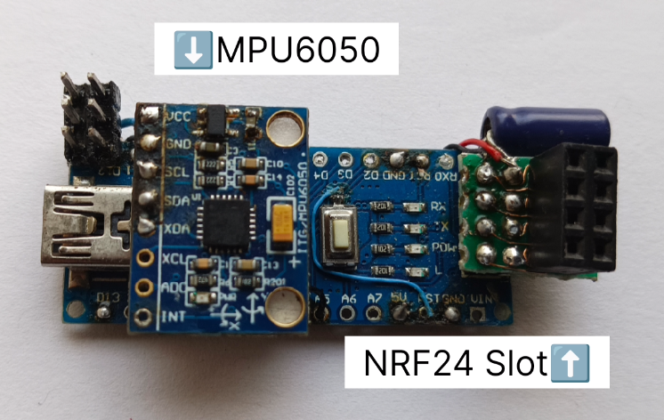
To make the flight controller I'm using ARDUINO NANO, MPU6050, NRF24.
I mounted the MPU6050 above the atmega chip and modified the ISP connector connection for the NRF24.
AMS1117 3.3v regulator is also attached to provide sufficient voltage to NRF24 and also 100uf capacitor to the NRF24 positive and negative to reduce some noise.
Adding Motor Driver Board
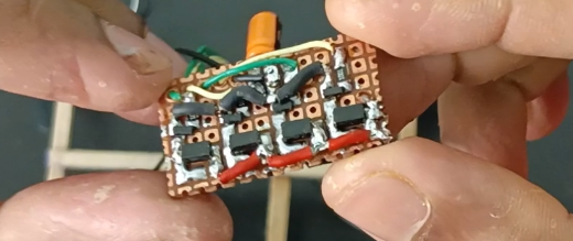
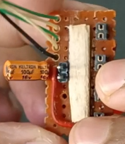
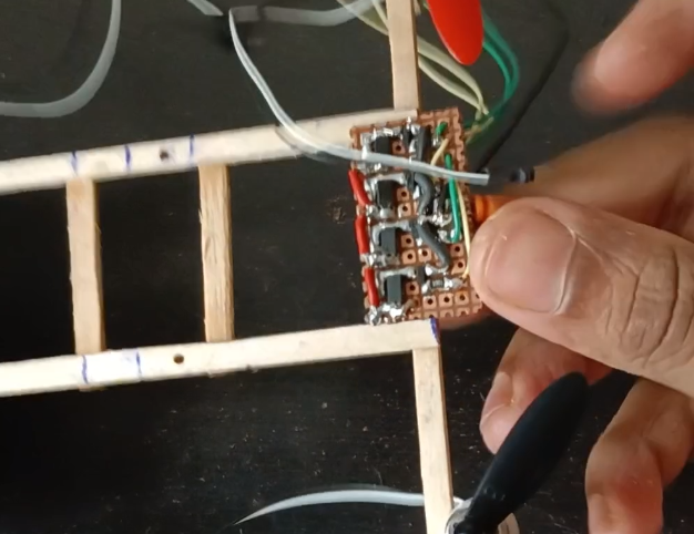
This custom designed motor driver board with SI2302 N channel MOSFET can drive 4 brushed motor individually. Each output can deliver upto 2.5 Amp of current which is sufficient for our motors.. Normally 8520 coreless motor with 55mm propeller consumes 1.2-1.8 Amp of cuurrent. I have also added some connectors for the battery and motor which will hep us to plugin and plug out the battery and also the motors, we can simply swip the motor wires if it's rotating in the wrong direction.
Adding Flight Controller and Voltage Booster
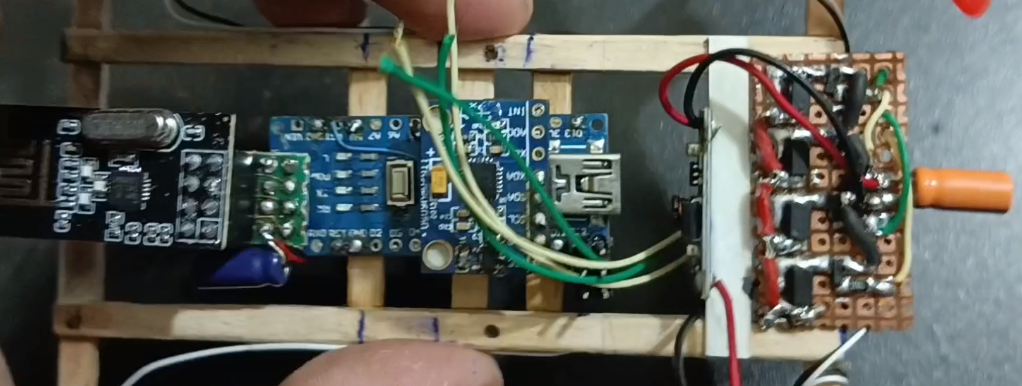
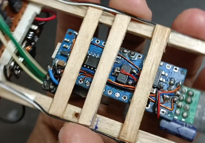
Now it's time to add the main controller FC and the 3.7 to 5v boost converter in our drone.
I glued the flight controller to the center of the frame(make sure that the MPU6050 should be on the center of the drone.
I'm using a single cell 3.7volt 25C li-po battery so to provide sufficent power to the main board I used this small size 5volt booster.
Attach the Battery
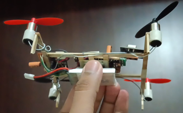
I'm using a 650 Mah 25C 3.7(4.2max) volt li-po battery which is attached at the bottom. I will suggest not fix the battery with the frame, to manage the drone load distribution you can adjust the battery position and also to replace the battery easily.
MultiWii Setup
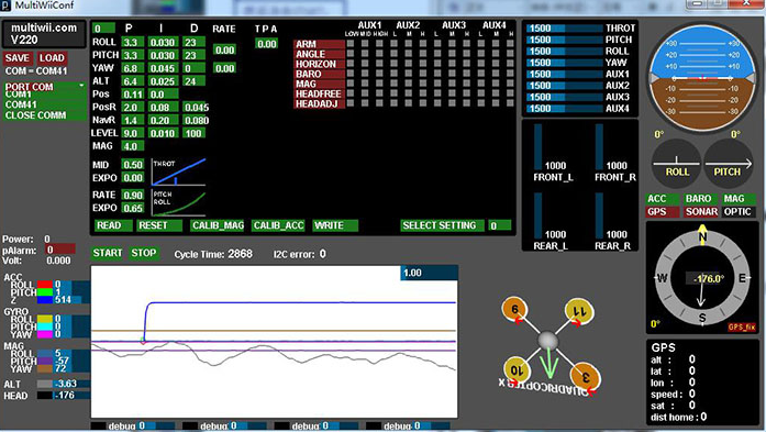
Now, Download the MultiWii files from the official website or you can use the modified code provided by an youtuber Channel name- ELECTRONOOBS for the NRF support code.
Then go to the Multiwii confog file open it on arduino IDE the select your settings then upload the code to your main board. After this make sure your main board is connected to your PC the open MultiWii application, select COM port the click on START, application will detect your board configuration and show you the RC model also. you must select an arm/disarm switch which is available on the top select any AUX switch you want to and then hit the write button and then read it to verify. To callibrate the accelerometer place your drone in a flat smooth surface then hit the "CALLIB_ACC" button, you can confirm it by the visual rpresentations. You can also see what your drone receiving from the transmitter in the MulwiWii window, check everythig, if "OK" then unplug the drone,connect your battery then ARM your drone fly it.
PID Tuning
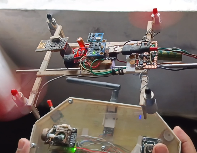
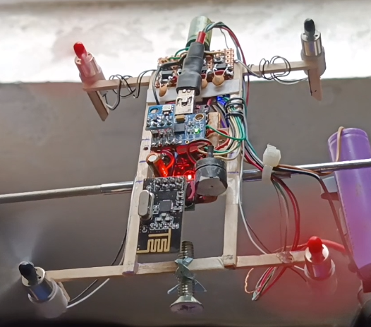
If your drone is not stable then plug in it with your PC then open the MultiWii and connect it. Then go to the PID section, Now it's time to play with the PID values.
For the PID tuning I deigned a simple stand as in the image. I have tried many combinations of PID values for pitch and roll and one of them just satabilized my drone not so much but will work.
Little Bit About the Transmitter
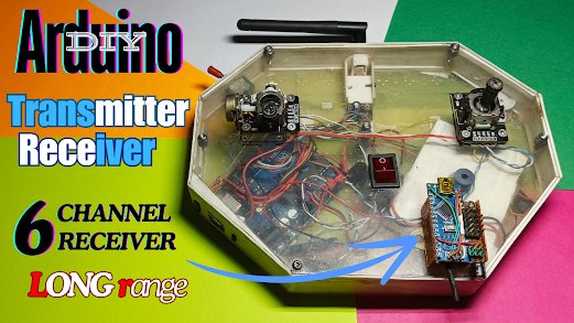
I,m using fully arduino based 6channel transmitter which I created some months ago.
The transmitter has a main controller ARDUINO UNO and a NRF24L01+PA+LNA antenna module and 2cell 7.4 volt rechargeable li-ion battery for longe operation time. Link of that video is attached. Video is available on my channel.
I have used AUX2 as ARM/DISARM and AUX1 for angle/baro/horizon.