SIMPLE ESP32 Radio Streamer
by hausofpayne17 in Circuits > Microcontrollers
12094 Views, 101 Favorites, 0 Comments
SIMPLE ESP32 Radio Streamer
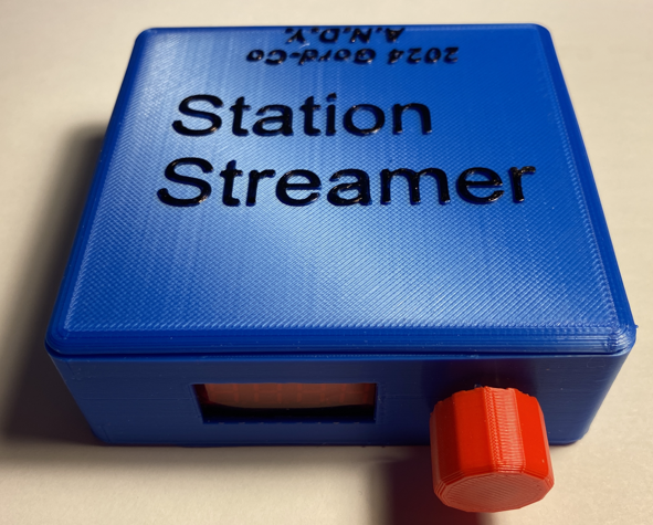
I wanted to build a SIMPLE streaming radio 'receiver' for my workbench so I can listen to radio stations while working on projects. It's substantially less complicated than the clock radio project I also designed.
Here is a demo video.
This project is of intermediate challenge. It's NOT a first project for newbies. ESP32 radio streaming is somewhat complex and you need to not only be comfortable with soldering and 3D printing; you need to be comfortable with Arduino coding and debugging.
This is a SIMPLE streamer. No scrolling station, artist, song metadata here. If you want to see this kind of extra information, you're better off choosing another Instructable like Shadowilla's linked below.
Some of its features:
- 4 digit, 7 segment LED Display with ability to display letter descriptors for the station ID (ex. 'nPr', '947', 'CLAS' etc)
- Rotary encoder for changing stations
- Save up to 10 stations
- Keep a preferred station as default on power-up
- Web-based configuration. NO MORE HARDCODING of internet credentials or station URLs!
I want to thank:
- Shadowilla for his "HiFi" Online Radio he published here on Instructables which uses a VS1053 MP3 decoder. He was very helpful with answering my questions.
- The Dronebot Workshop for the tutorial on how to use the WiFi Manager for web-based provisioning of internet credentials and other settings. It also demonstrates how to use SPIFFs to store the preferences in a file on the ESP32.
LET'S GET BUILDING!
Supplies
- ESP32 Wroom32 Dev Board - any board will work. I used an inexpensive generic kit I ordered online
- VS1053 MP3 Encoder/Decoder module
- 0.56" 4 digit 7 Segment LED Clock Display TM-1637 library compatible
- Coloured acetate sheet to make filters for the display to make it more readable (optional).
- Rotary Encoder Module - HW-040 or similar
- SPST momentary contact switch
- 10K Ohm pulldown resistor
- 50mm x 70mm prototype board. You may want some scrap prototype board to mount the config/reboot button so it's easier to mount to the inside back of the case.
- Wire, solder, M and F terminal strip if you don't want your ESP32 and the VS1053 permanently soldered to the board
- Audio isolation transformer module (you may or may not need this based on the amplifier you're using in your finished project. If you're getting an awful buzzing on your amplifier, you may have a ground loop situation and need an isolation transformer module.
- PLA filament for 3D printed enclosure
- PATIENCE!
If you'd prefer to NOT use a USB cable to power the final project, just choose a 5V DC adapter in the 800-1000mAh range and connect it to the 5V and GND pins on the ESP32.
Circuit Construction
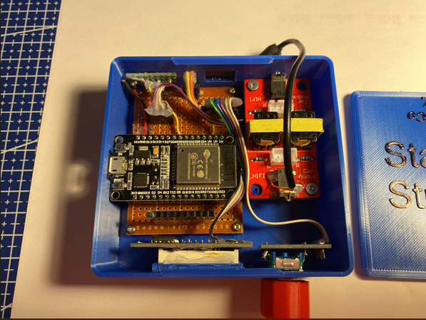
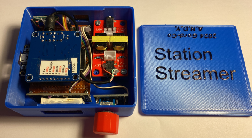
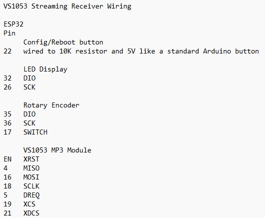
This project is not for a first-time maker. There's an expectation you know the basics of buttons, soldering etc. You can lay out your circuit design as you feel is best for your needs. A Fritzing diagram would be REALLY cluttered so it was not created.
The pin mappings for the various components are in the image.
This is a 'tight' circuit that was designed to fit on a 50mm x 70mm prototype board and fit in a compact 3D printed enclosure. If you're going to use the same 3D printed box, just take your time with the close soldering that is required.
As stated in the circuit list, the Config/Reboot button is wired like a standard Arduino pushbutton with one side going to GND through a 10K pulldown resistor and to the GPIO pin on the ESP32. The other side goes to 5V.
By all means breadboard it first to get it working.
For compactness, I trimmed the strain relief fins off the audio jack that goes in to the 'Phone' jack on the VS1053 module so the cable can bend in the tight box. The other side is wired directly to the pins on the isolation transformer. Just use a continuity tester to find the corresponding solder pads that match the audio jack.
Upload the Sketch
This sketch uses the VS1053_ext library and the ESP32 WiFiManager library as well as the TM1637 display module libraries. Make sure they're downloaded and installed in your IDE.
For simplicity, you can use the VS1053_ext "fritz" sketch to test your circuit with a known, working URL. You'll need to provide your own network credentials and a valid URL in that sketch. Make sure you change the pin mappings to match the circuit.
Create a new folder and call it 'SuperSimpleStreamingSourceFinal' and put the 3 files in the folder. Open your Arduino IDE and open the project.
Once it's open, upload this project sketch and restart the ESP32 with the Config/Reboot button held down so the circuit will enter Configuration mode.
IMPORTANT:
There is a block of 3 lines of code in the VS1053_ext.cpp file in the .begin() function that I had to comment out because the board I use would not start up correctly most times. The comment in the .cpp file even says, "May not work for all boards". It took some hunting. If you're finding the board is not properly starting up after the player.begin() command in setup(), try commenting out these lines.
The displayText.h class handles parsing the stationIDs for rendering in the LED display.
The configSave.h class handles reading the preferences and saving the preferences.
You may want to UNCOMMENT the SPIFFS format line in the configSave.h class file. It will format the SPIFFS file space on the ESP32 if one does not already exist. You can uncomment it and re-upload the sketch once you've had it create the SPIFF area.
Configuring Your Streamer
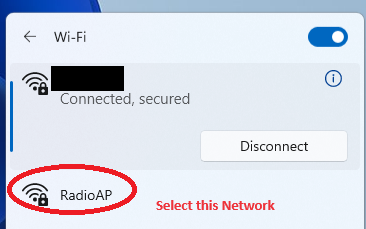
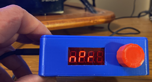
With "CFG" showing in the display, open a device like a phone or laptop and go to the network browser.
Select "RadioAP". This is a webserver created by the ESP32. Click 'Connect'.
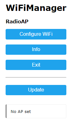
A browser will open on your device and show the WiFiManager.
Click on Configure 'Configure WiFi'.
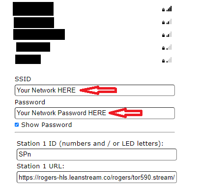
Enter your home network's WiFi network and password.
Then enter at least one Station ID. You can use numbers (ex. '947') or any letter that can be represented on a 7 segment LED. Ex:
AbCcdEFfGHhIJLnOoPrStUuY1234567890-_
You may use up to 4 characters for a station ID.
Enter the URL for the streaming station you want to play.
You may use this website to search for station URLs.
NOTE: Some stations are slow connections (ex. 48kbps) and may not be playable with the VS1053_ext library. Choose the fastest connection offered.
MAKE SURE YOU'VE entered your network ssid and password at the top of the screen before proceeding.
Once you've entered your stations and URLs, click the SAVE button at the bottom of the screen.
The program will attempt to save the data and then the ESP32 will restart and attempt to sign in to the network you specified. It will attempt to play the first station.
If all was saved correctly, you should be able to rotate the encoder to move through the stations. Pausing on a station will cause the ESP32 to then attempt to connect to that URL and play the station.
To save the displayed station as your preferred/default station, press the encoder knob. You will see, "SF" (save favourite) to indicate the station was saved to the EEPROM as the preferred station.
3D Printing Your Enclosure
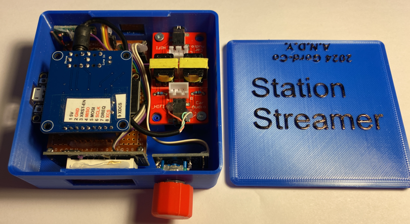
Download these .STL files and slice them with your printer's software. I used 5% infill and support. Print them in your desired filament type/colour.
You may need to file the corners of the lid's lip to have it fit the case.
Two kinds of knob files are provided. Most of the encoder modules have a D-type shaft. So print the appropriate knob for your encoder or use a different knob. You may need a bit of hot glue to make the Dknob fit snuggly to the shaft.
Use small screws to mount the circuit board and isolation transformer(if used) inside the enclosure.
Hook everything up and try it out!
ENJOY YOUR MP3 Streamer!
NOW GO AND MAKE SOMETHING WONDERFUL!