RpiGarageDoorDistanceSensor
by Ishreet123 in Circuits > Raspberry Pi
1689 Views, 11 Favorites, 0 Comments
RpiGarageDoorDistanceSensor
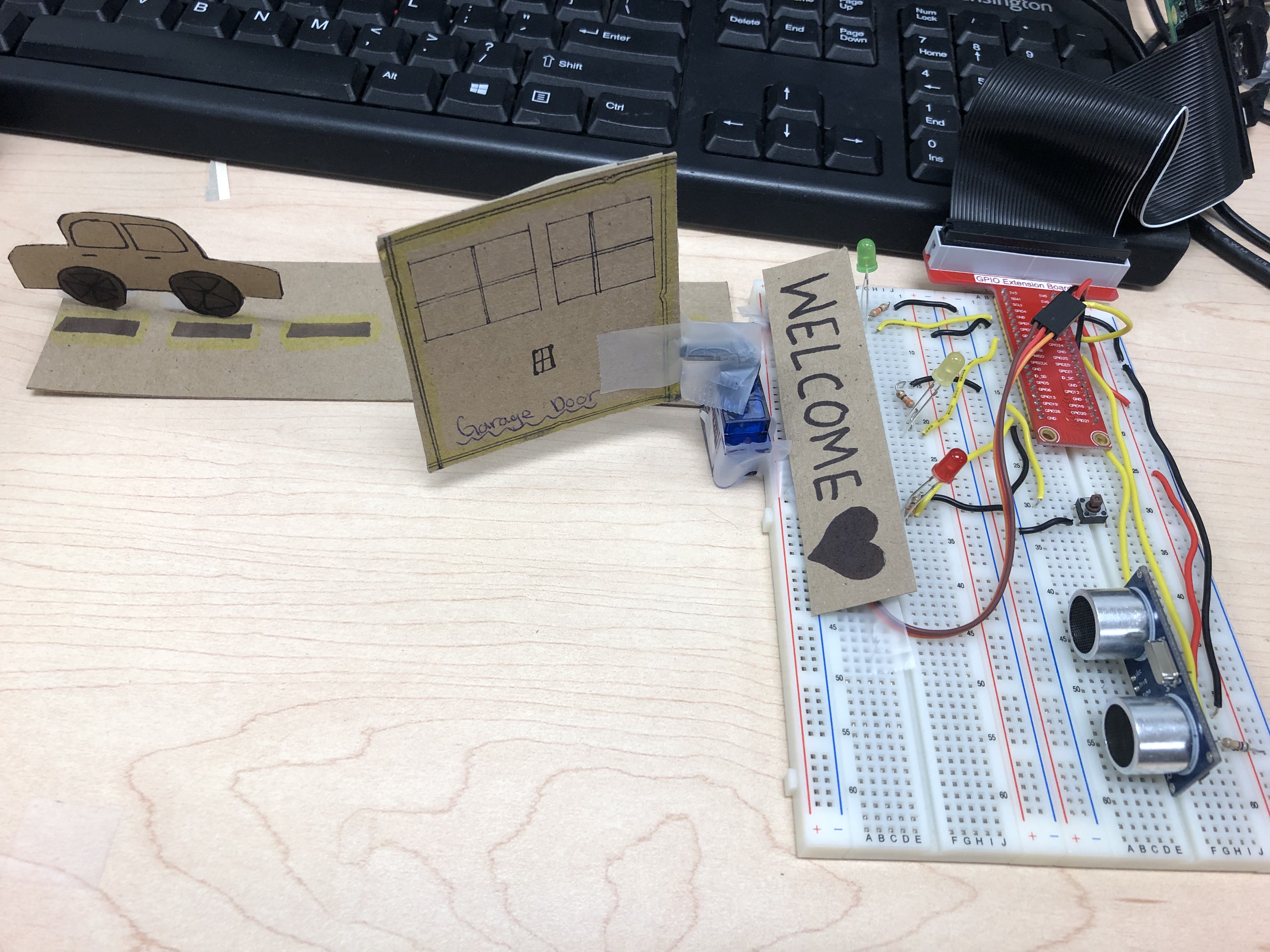
This tutorial will give you a step by step process on how to create a garage door distance sensor for when a car is entering a garage, with the raspberry pi.
Gather Your Materials


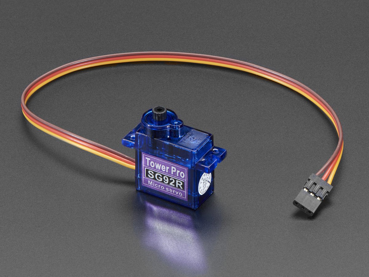
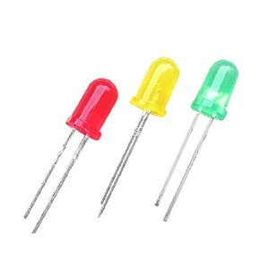
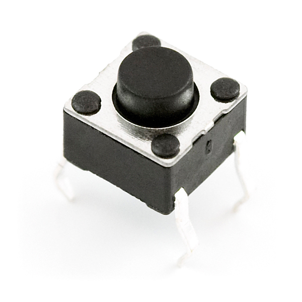
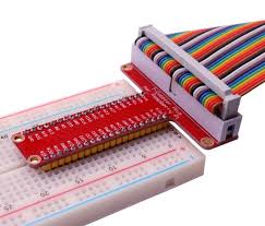
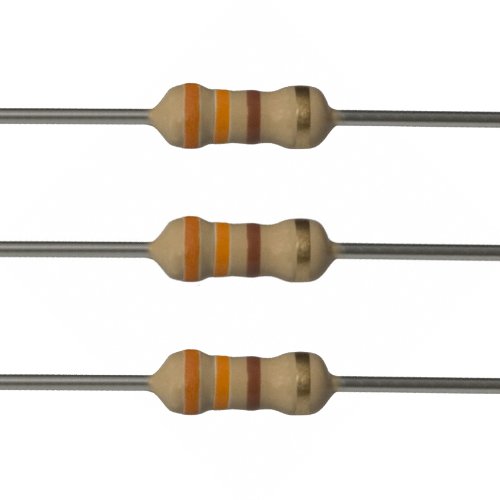
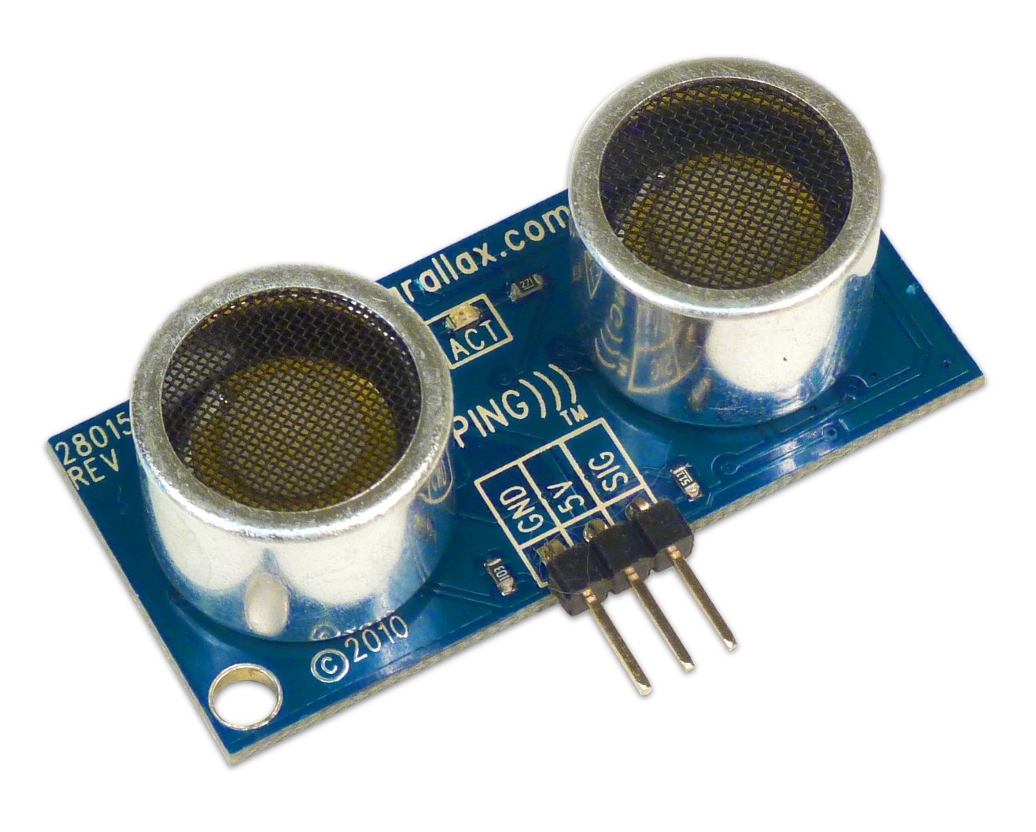

Start off by collecting the following materials:
1. Raspberry Pi
2. Breadboard with t-cobbler (attached to Rpi)
3. Distance sensor
4. Jumper wires
5. Green, red, and yellow LEDs (one of each)
6. Two 560 ohm resistors
7. Three 330 ohm resistors
8. One button
9. Micro Servo
Wiring the Distance Sensor
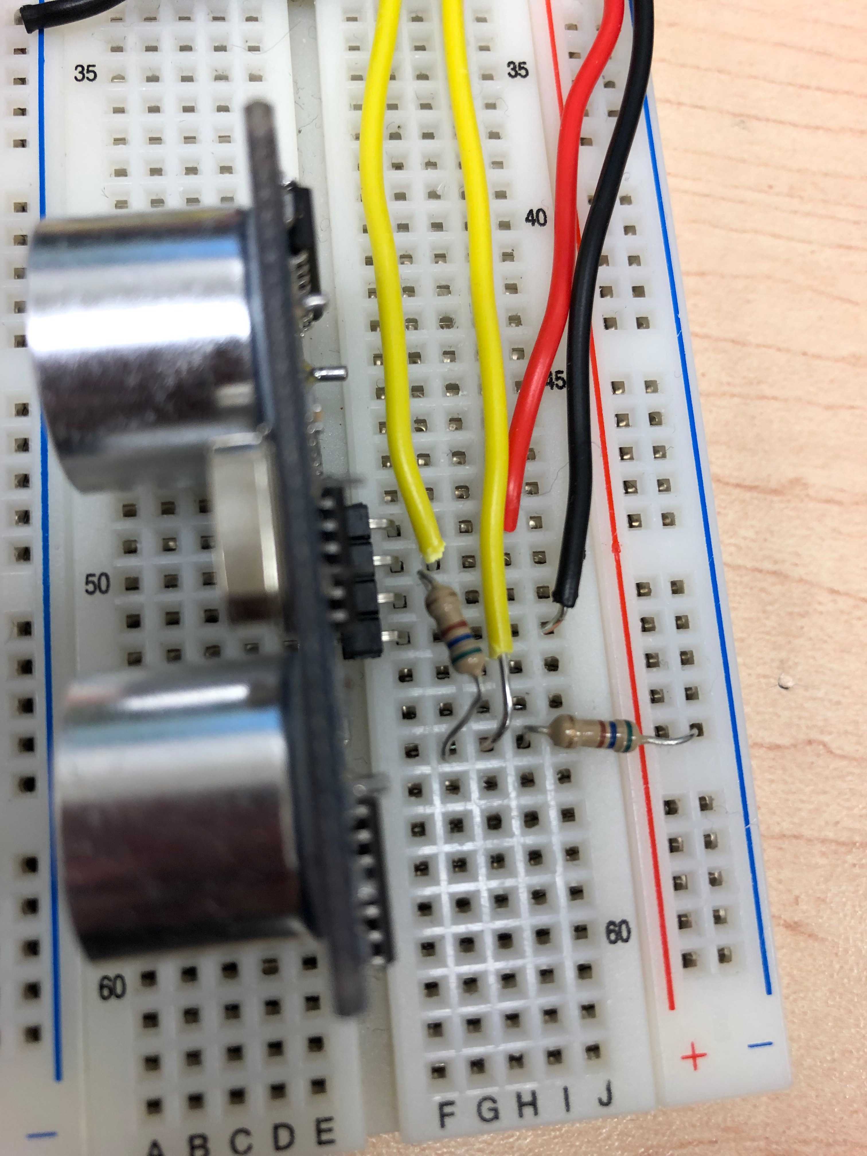
Stick the Distance Sensor into the breadboard vertically. Then using jumper wires, put the VCC pin into the 5V and the GND pin into the ground rail of the breadboard (make sure that your GND and power rail is connected to the GND and 5V of the rpi).
Then using two 560 ohm resistors, connect one of the resistors to the echo pin going vertically. Using a jumper wire, connect one side to GPIO 24 whereas the other side connects to the resistor. Then using the second resistor, connect one leg to the first resistor and the GPIO pin, and the other leg to the ground rail (refer to picture above).
Setting Up the LEDs and the Button
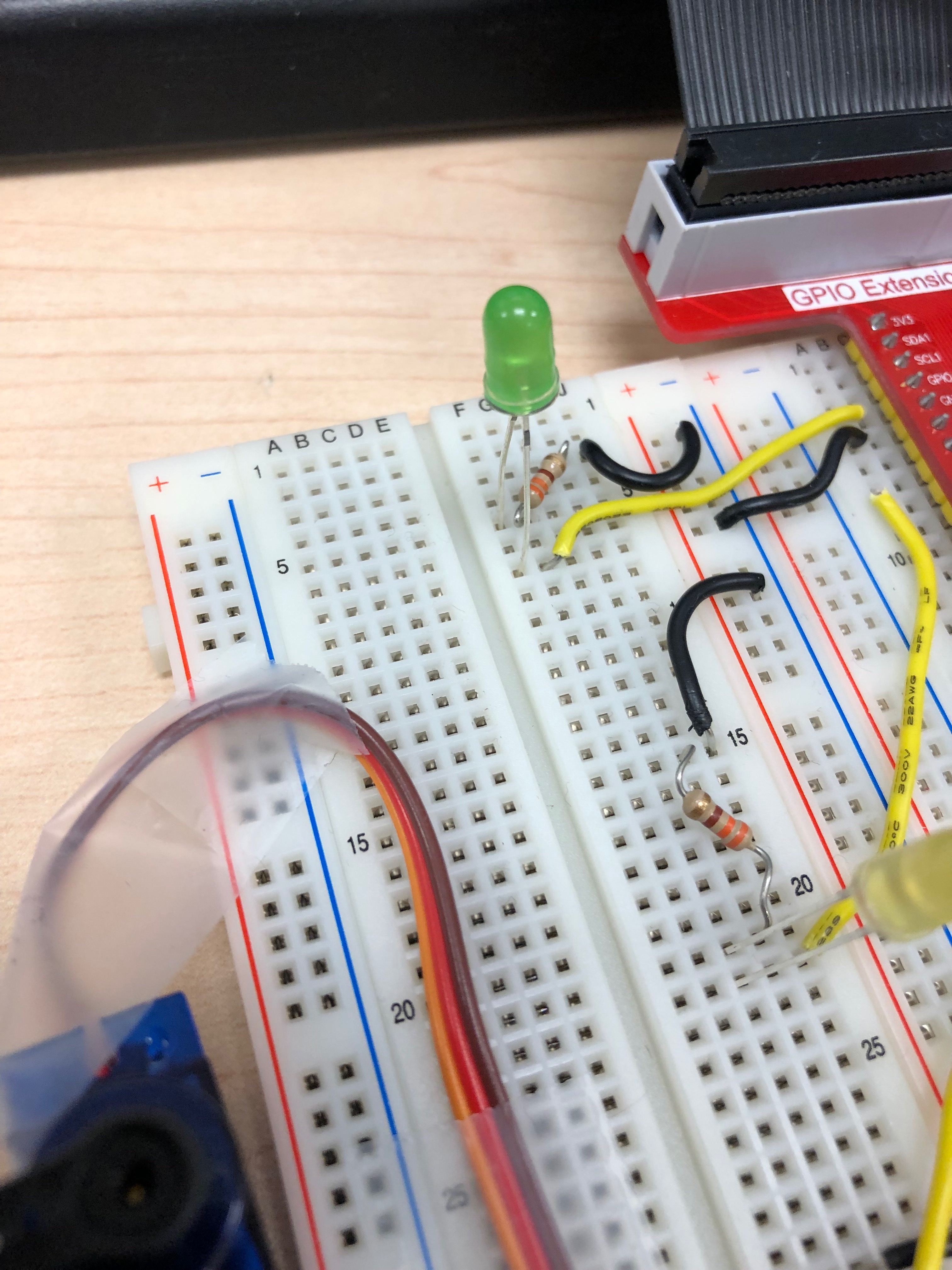
The LEDs will indicate how close and how far you are from the distance sensor
Setup your three coloured LEDs on the breadboard going vertically. Using the 330 ohm resistor, connect each LED's short leg to one side of the resistor which then connects to the ground rail. Connect the other leg to a GPIO pin using jumper wires.
GPIO pins For Each LED:
Red: GPIO 26
Yellow: GPIO 27
Green: GPIO 4
The button will give command to the servo to move a certain direction which will then open and close the garage door.
For the button connect the bottom leg to the ground rail and the top leg to GPIO 13.
(refer to the picture above)
Connecting the Micro Servo
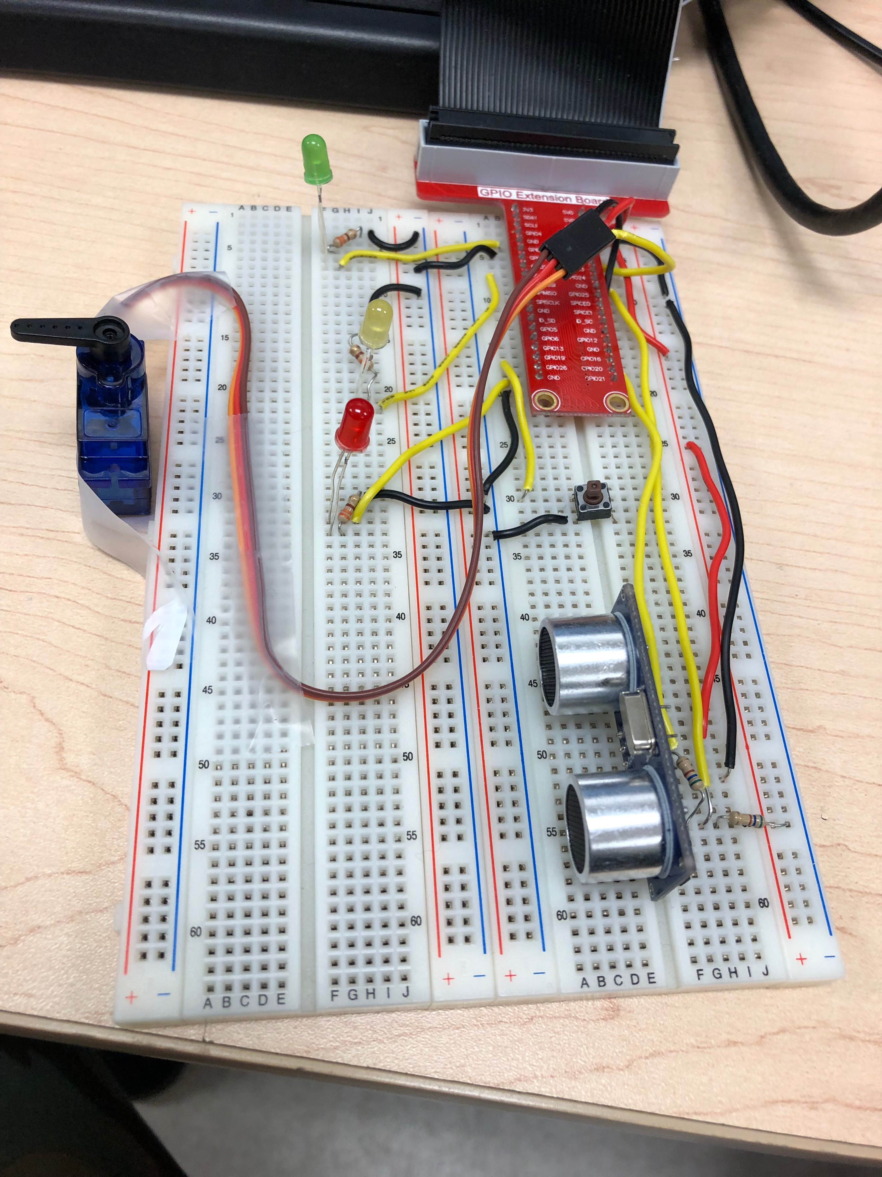
The servo would play the role to open and close the garage door.
Using jumper wires (or female to female wires), connect the orange wire to GPIO 18, the red wire to 5V and the black wire to the GND pin.
(Tape the servo to the breadboard so when the servo moves the "garage door" it will stay upright like shown in the picture above)
The Code
Here is the download to the code.
Downloads
Customize

Now you can make this project look like a car entering a garage door by using different materials and your creativeness!