Rotating Vegetation Monitoring Camera - VegTrack360 (v3)
by FlorianEllsaesser in Circuits > Cameras
846 Views, 7 Favorites, 0 Comments
Rotating Vegetation Monitoring Camera - VegTrack360 (v3)
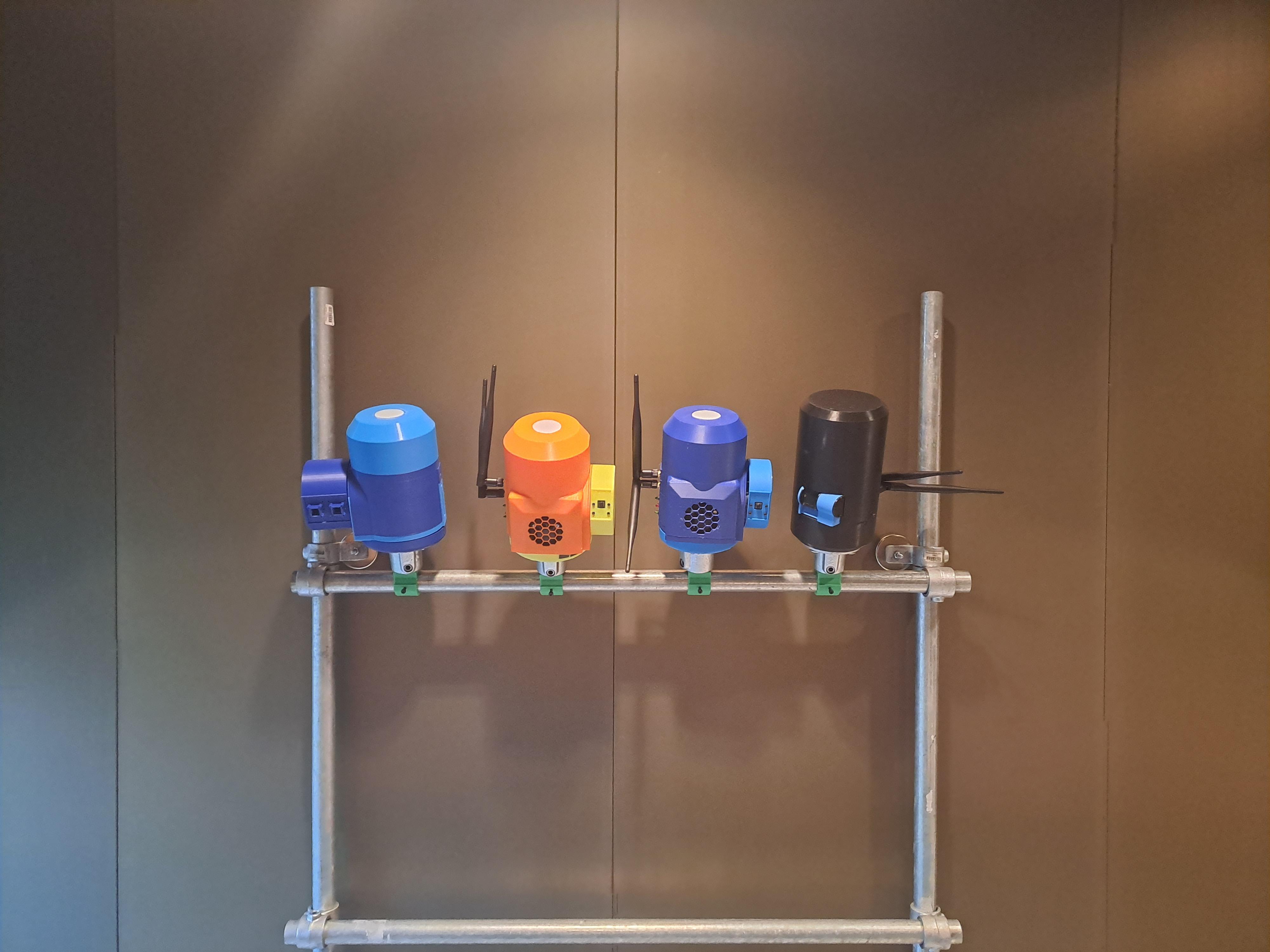
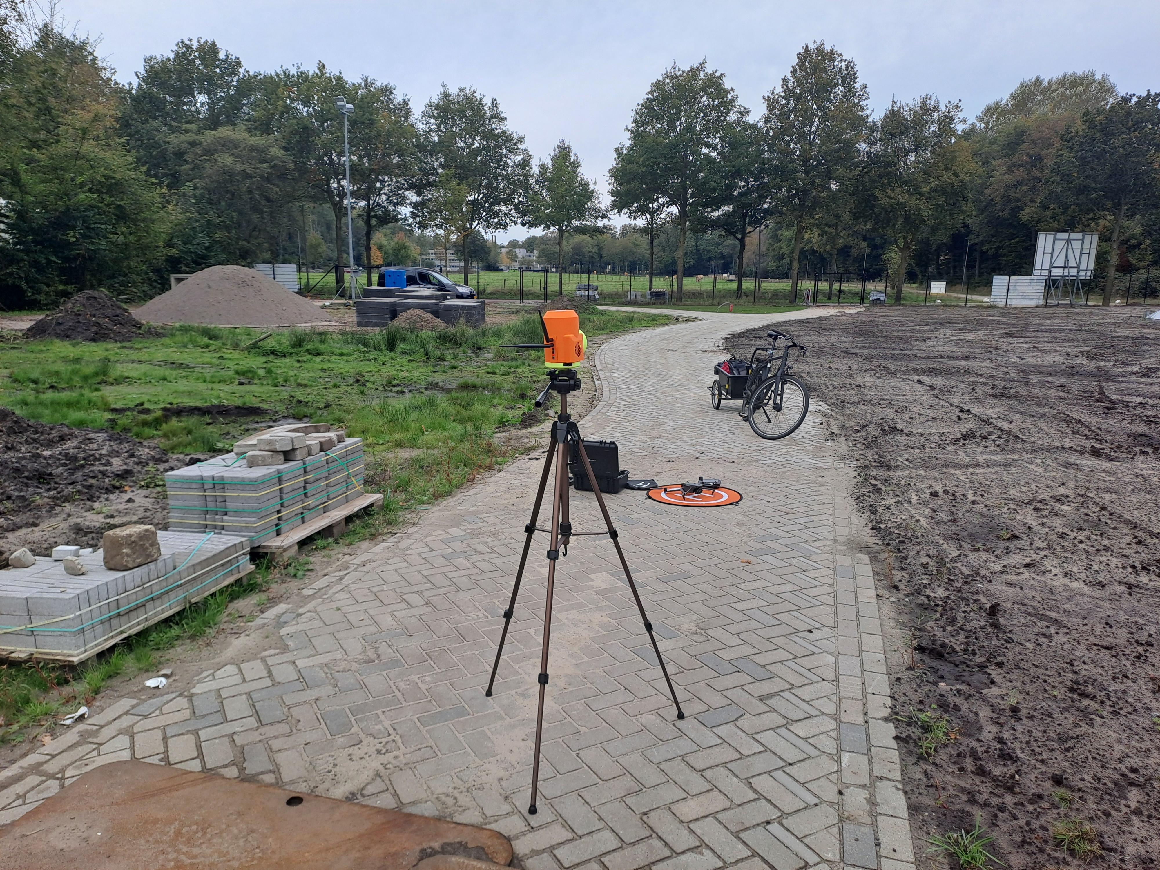
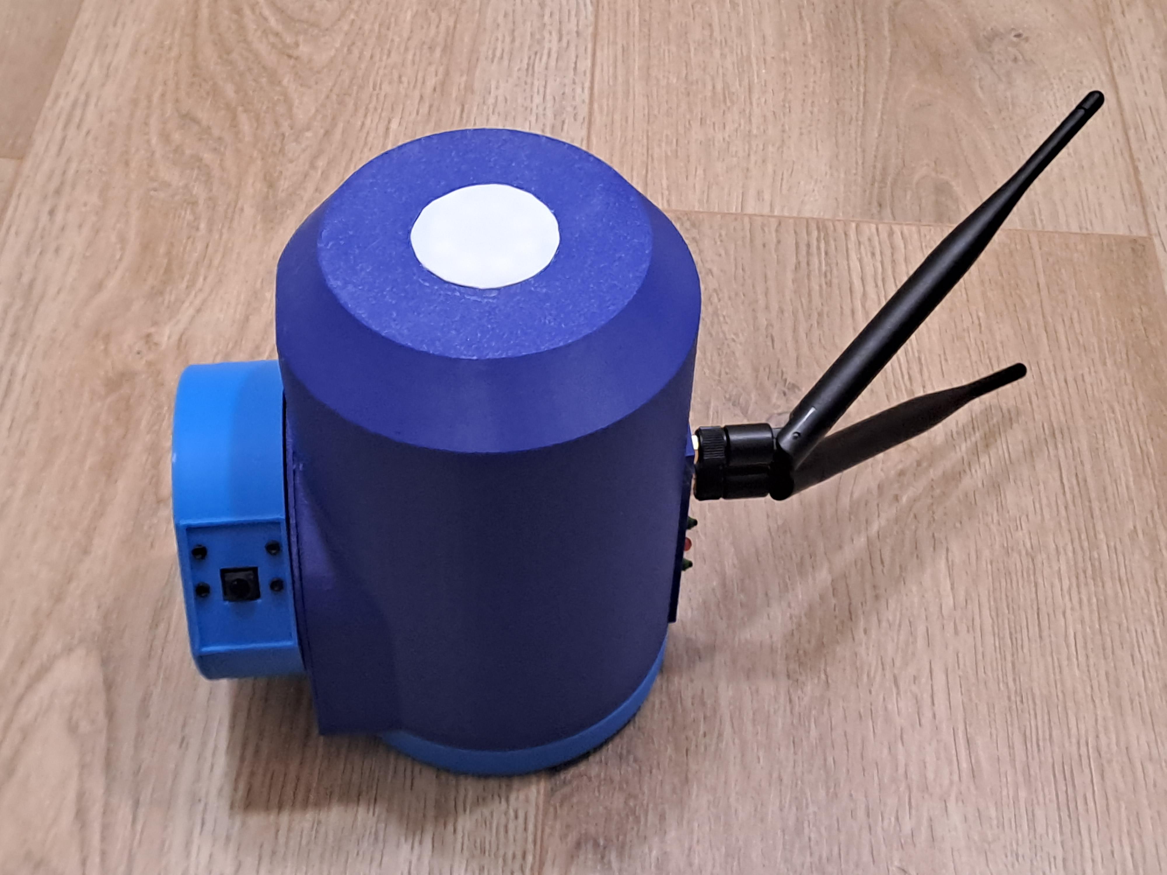
Monitoring outdoor spaces presents unique challenges. A single fixed camera, like the PhenoCam, captures only one angle of a complex scene. Achieving a full 360-degree panoramic view requires multiple cameras pointing in all directions. While this is feasible with affordable RGB cameras, replicating the setup with more specialized equipment like thermal cameras or spectrometers can be prohibitively expensive.
That’s where the VegTrack360 comes in. This project introduces a simple rotating camera platform that uses a single camera to create 360-degree panoramic images. By leveraging a rotating mechanism, the VegTrack360 provides a cost-effective solution for capturing comprehensive views, whether you’re monitoring your backyard, a field, or a wildlife habitat.
Welcome to the VegTrack360 Build Tutorial!
In this guide, I’ll walk you through creating a rotating camera platform designed for precise outdoor monitoring. This tutorial is also available on Hackaday.io but in a different style (more concise). You can find the project files and code on github.com and this is also where I update and store the latest version of this project.I upladed a first example data set on 4TU.ResearchData that shows a few sets of images and panoramas generated with the VegTrack360.
This simple setup tutorial uses a single RGB camera to capture 360° panoramas through horizontal and vertical rotation. Once built, you can easily upgrade the system for thermal imaging or multispectral analysis.
This project was made possible with funding from the NWO Open Science Fund. We are deeply grateful for their support in advancing open science and remote sensing innovation.
Ready to get started? Let’s dive in!
Supplies
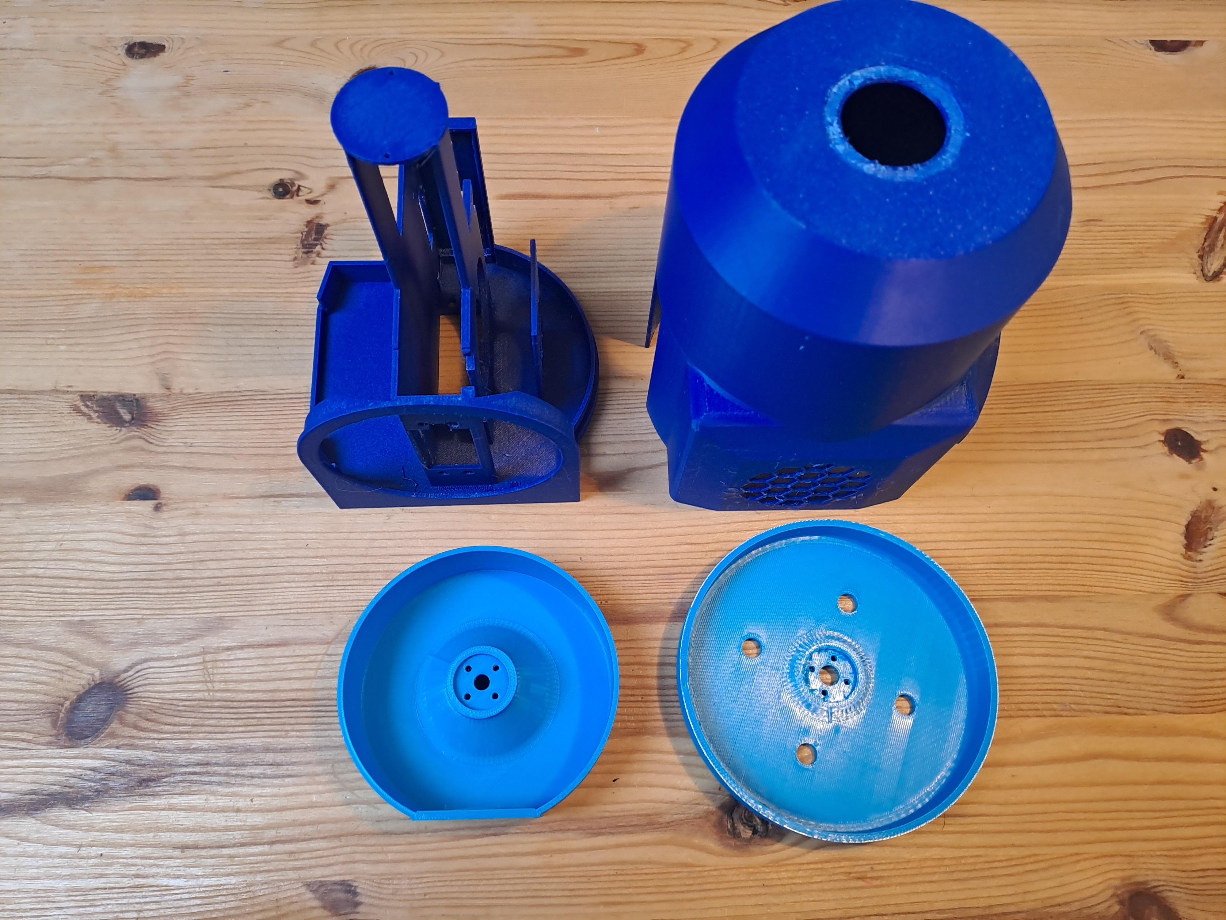
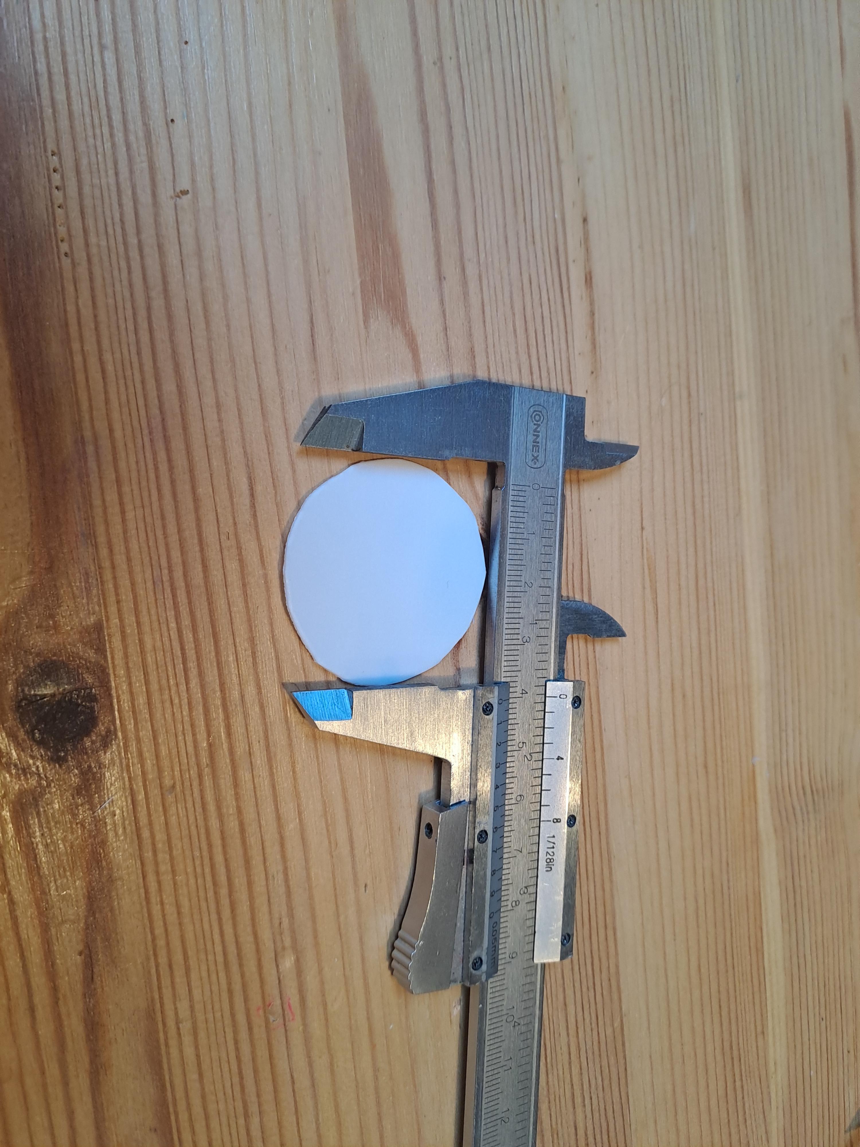
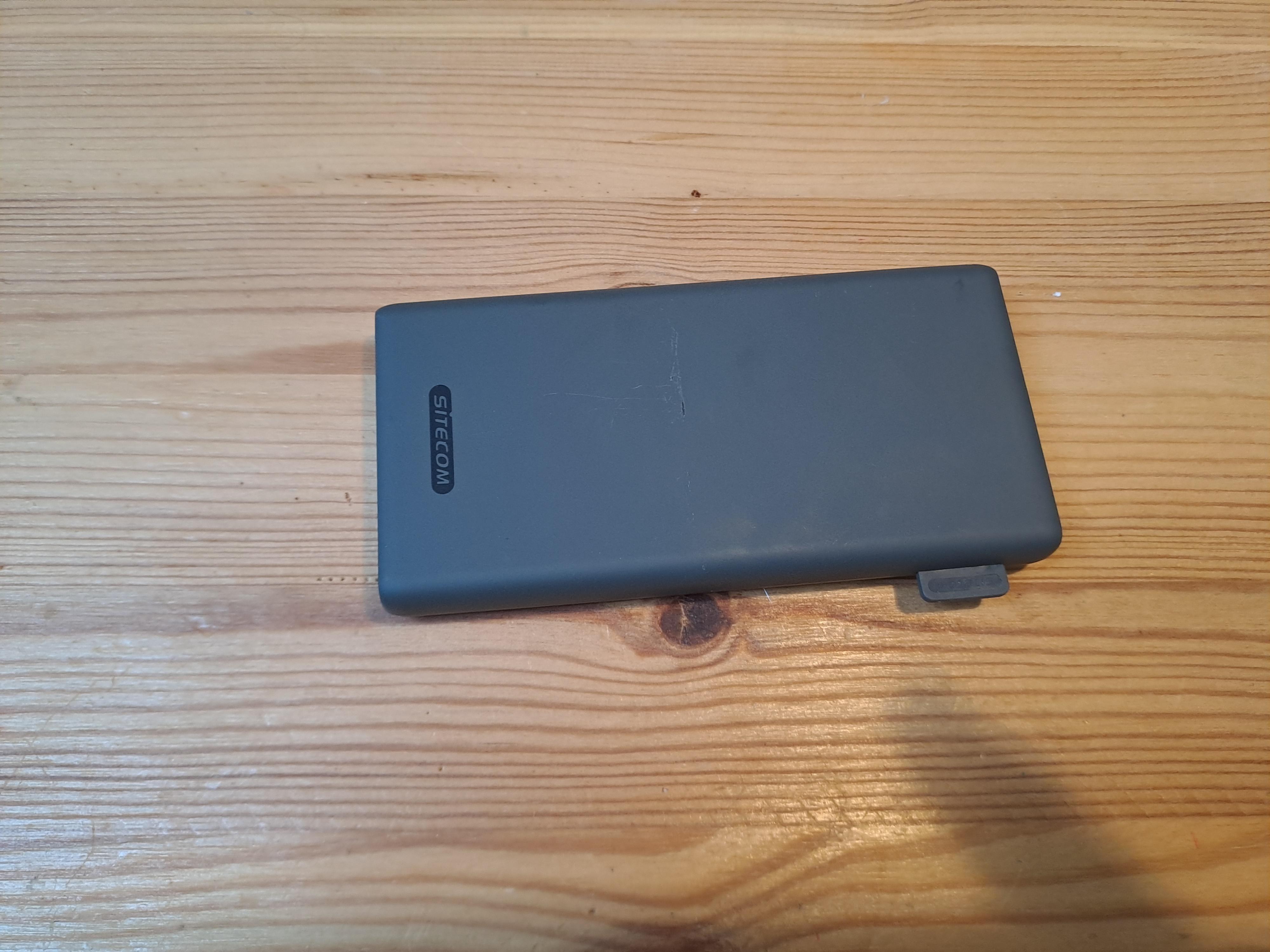
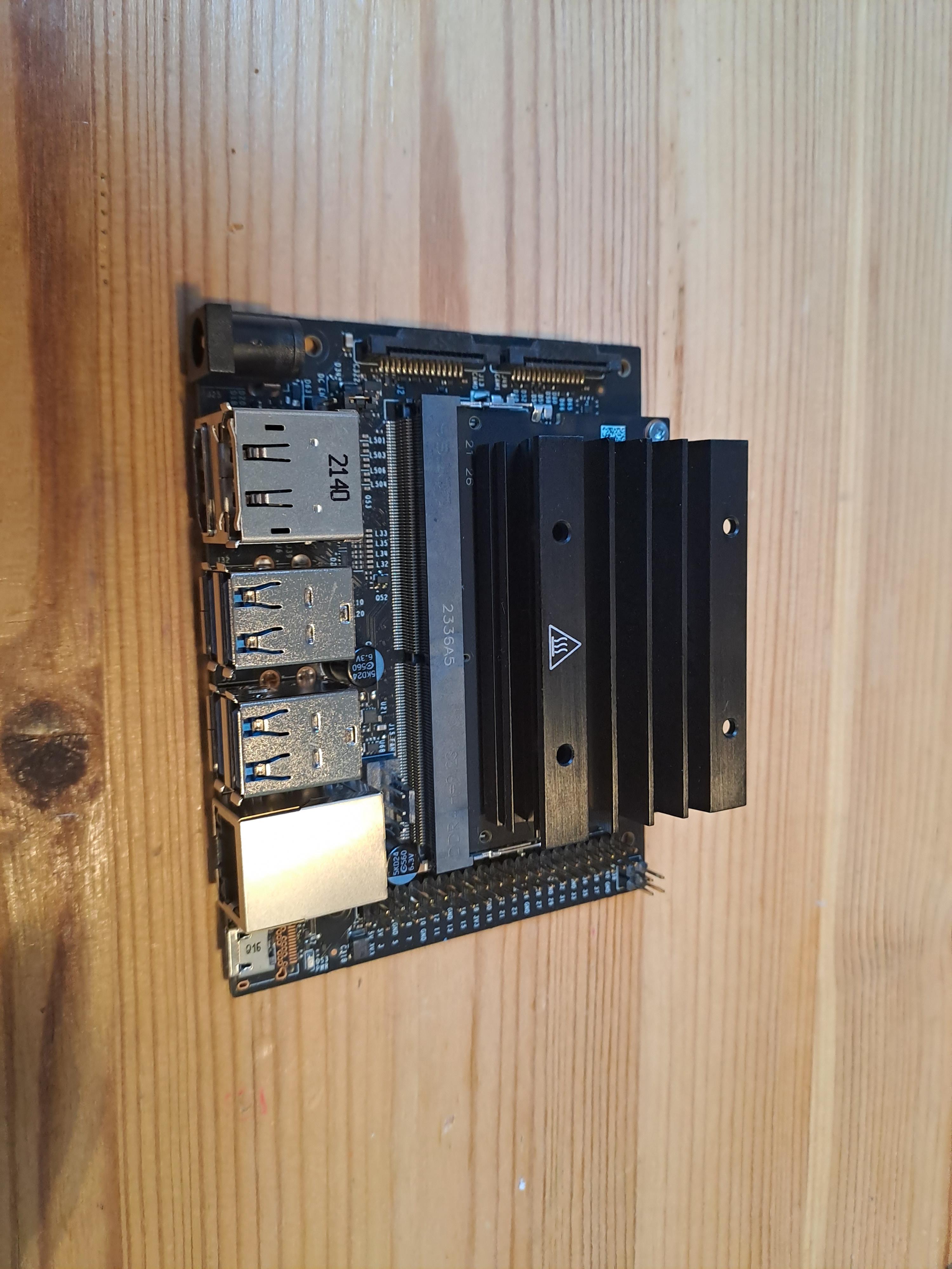
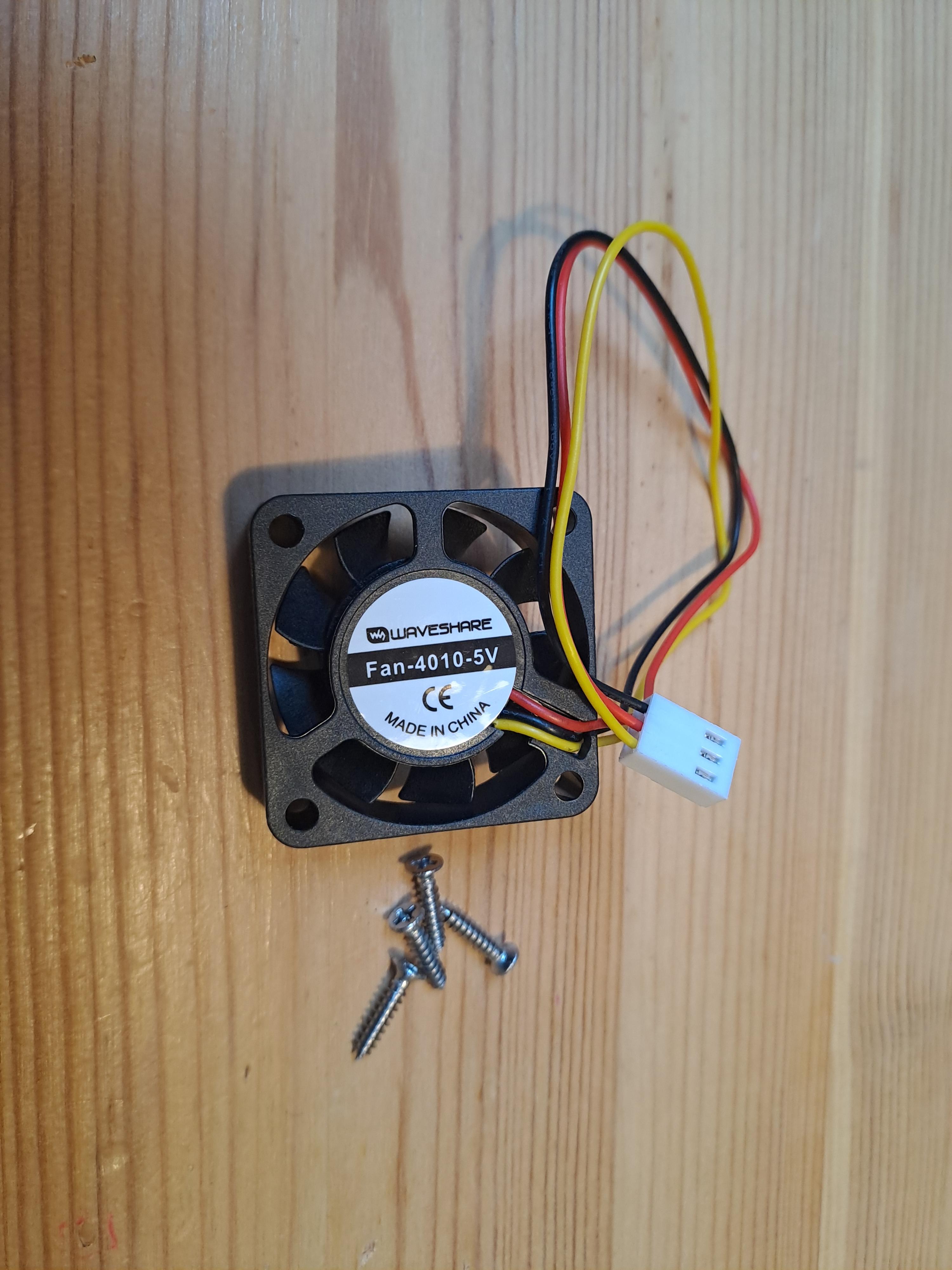
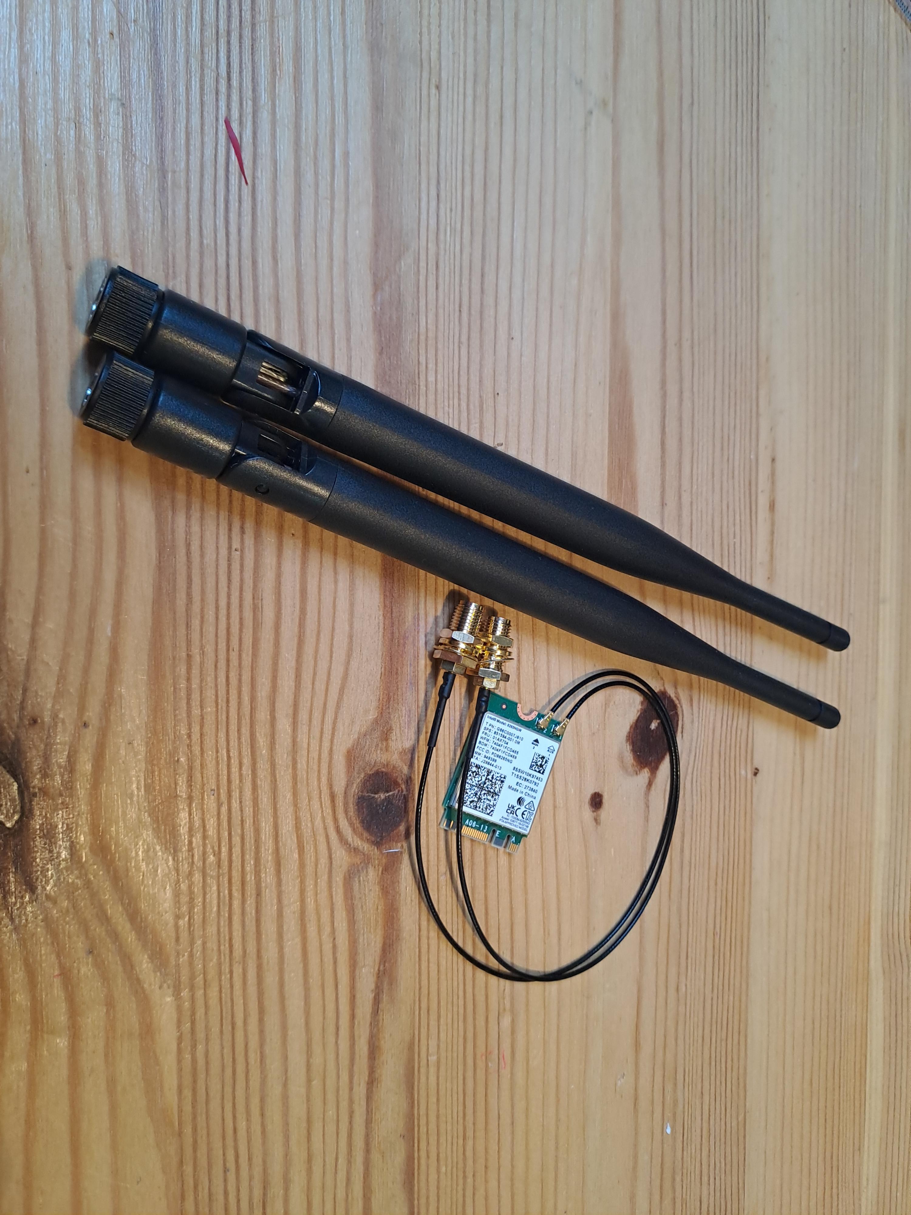
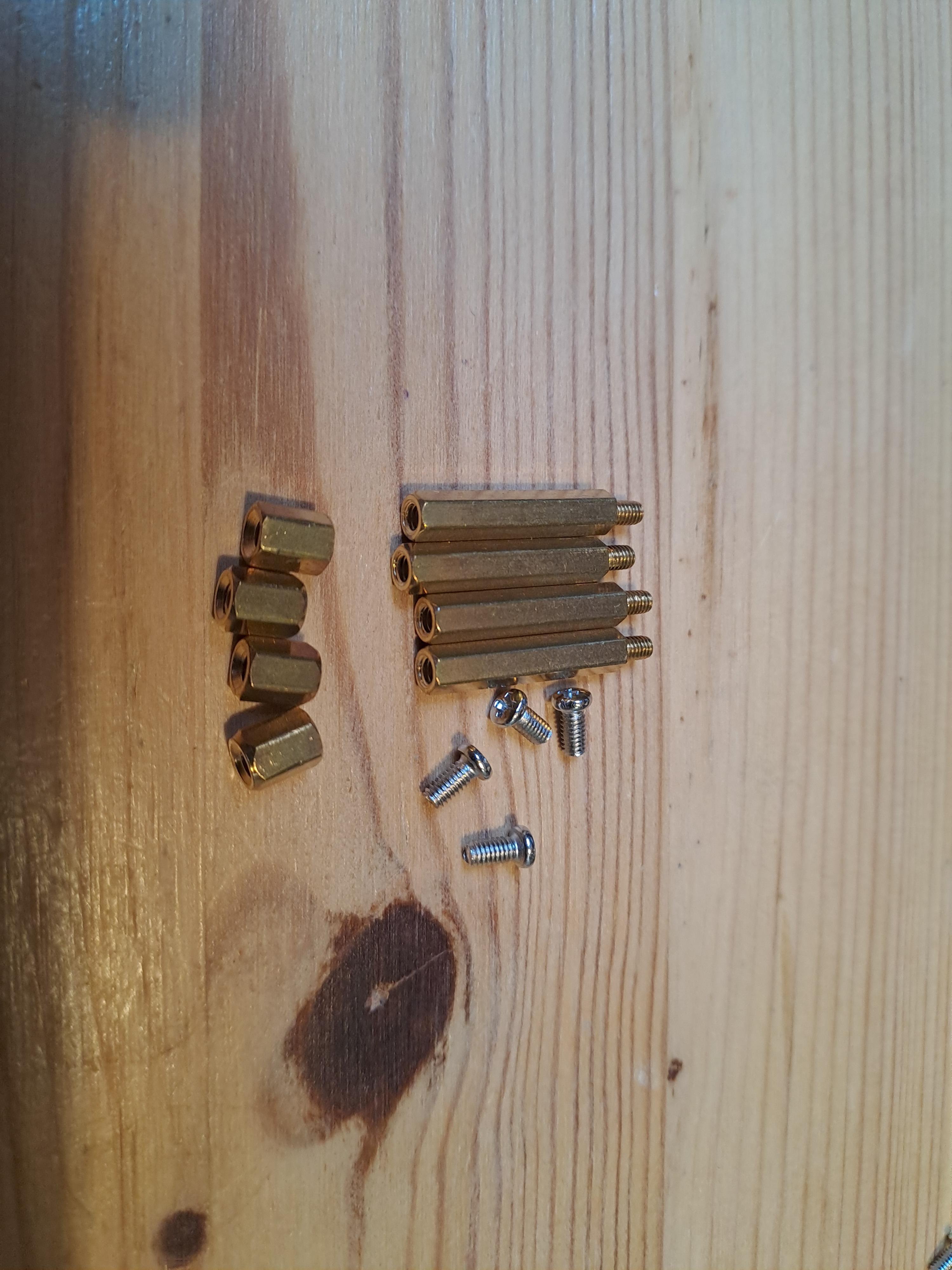
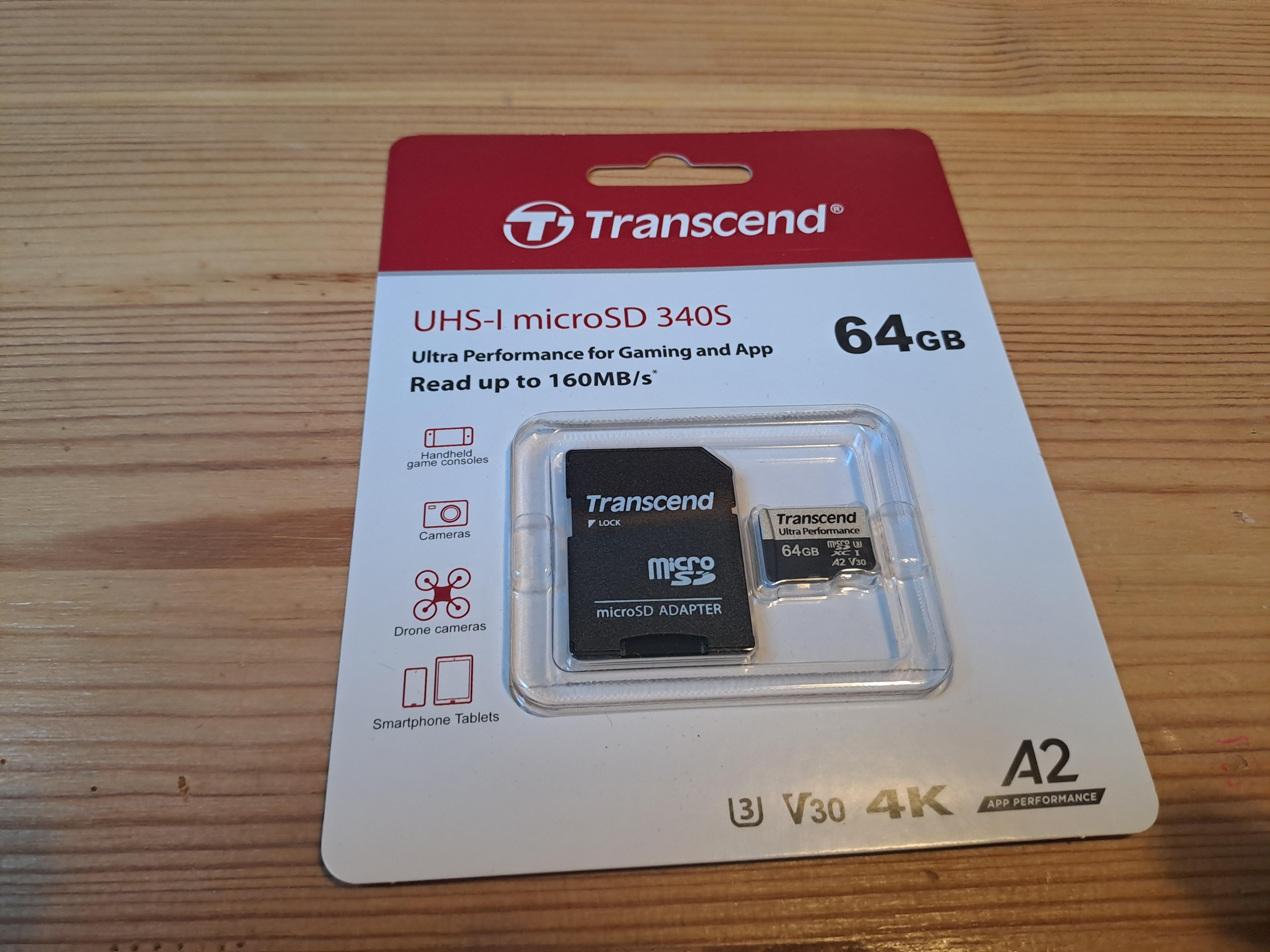
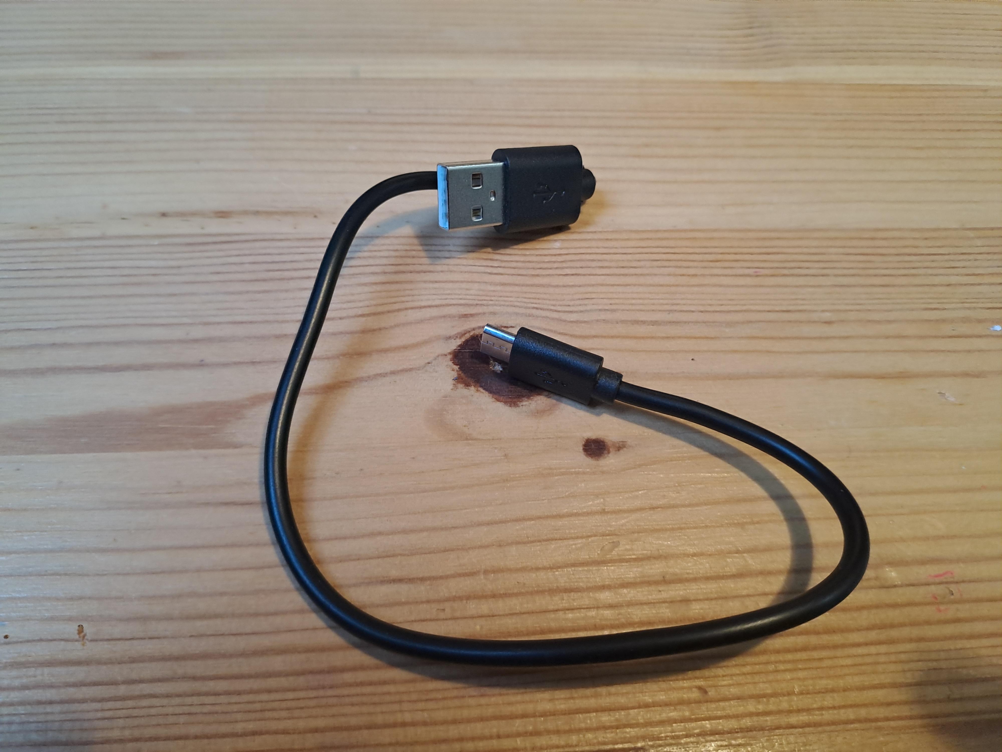
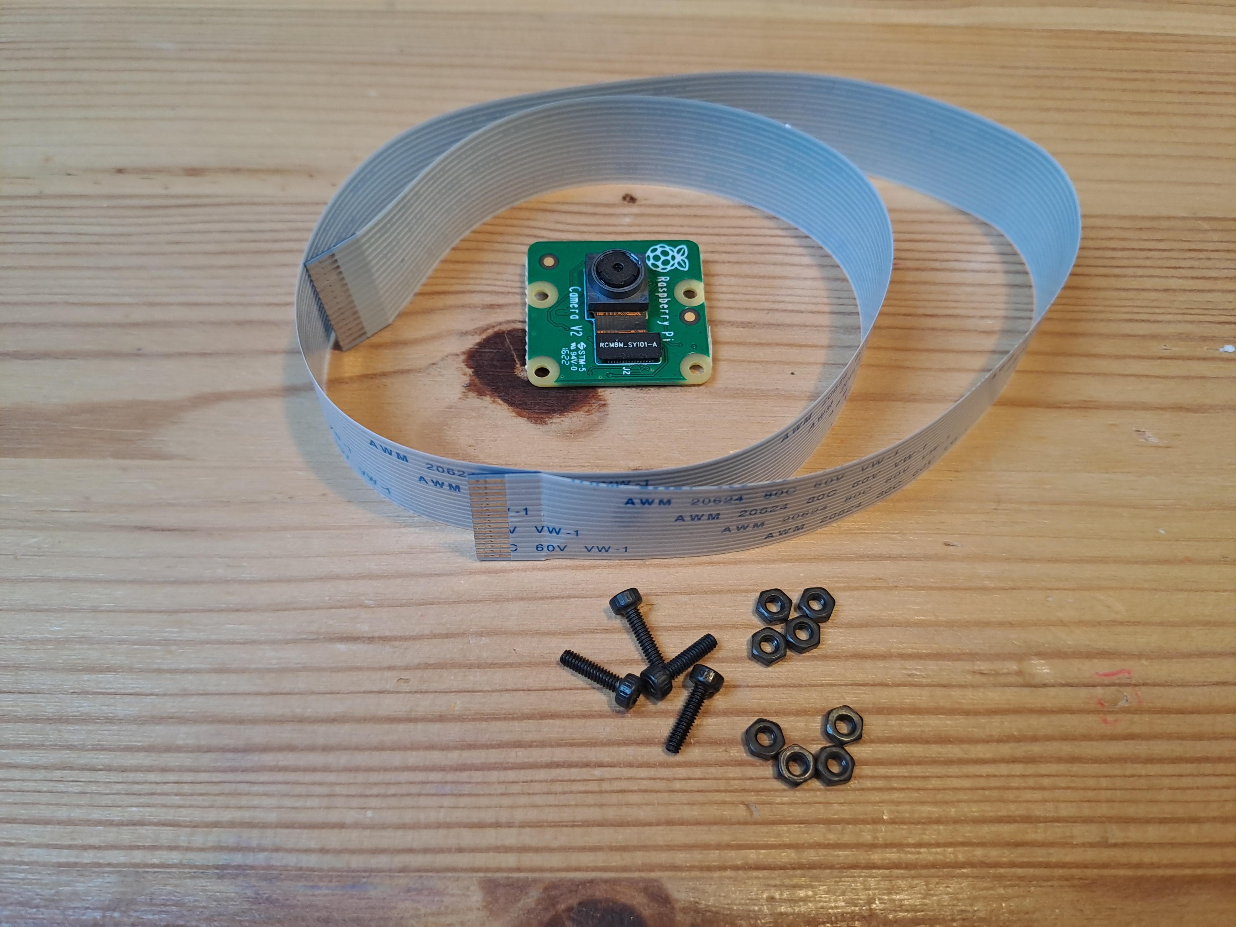
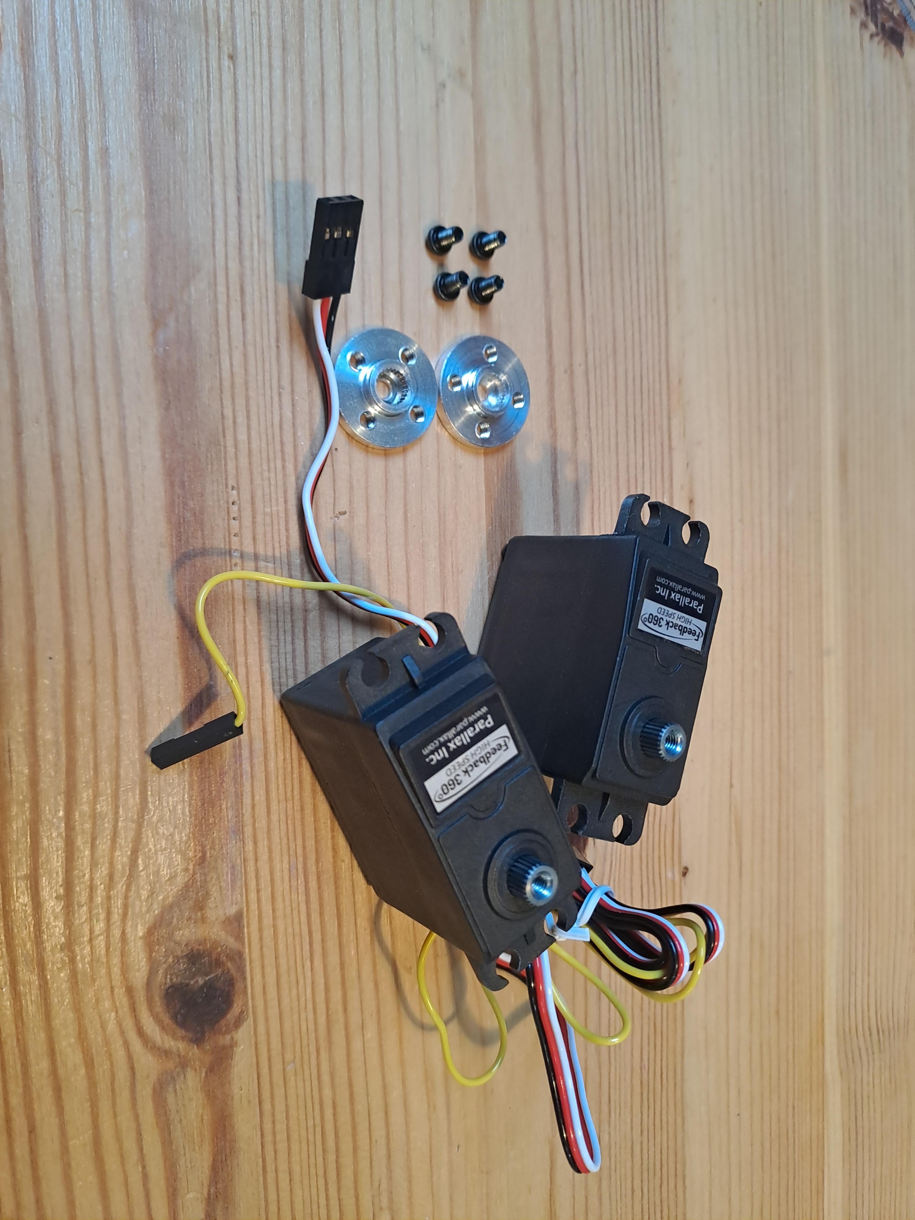
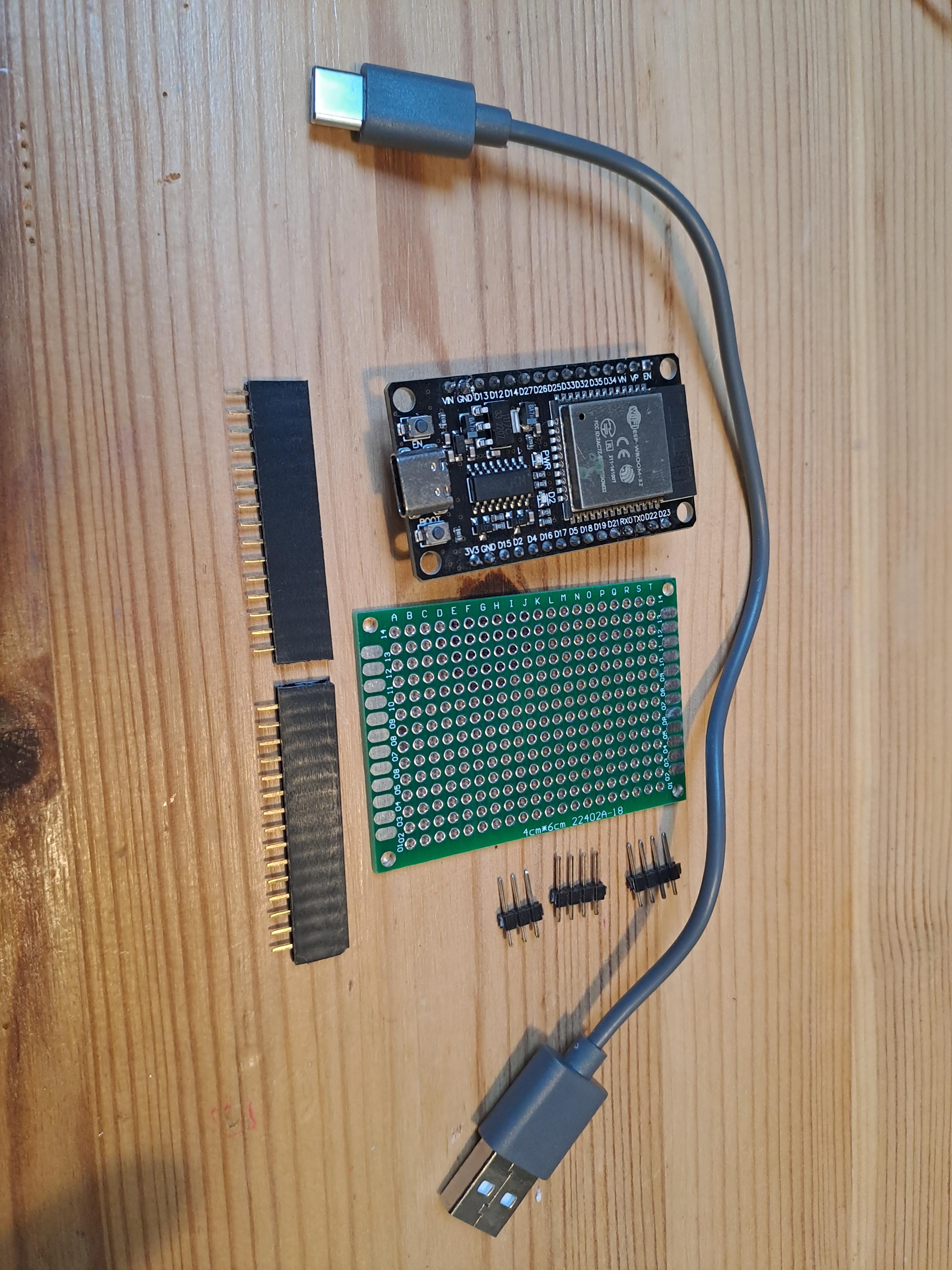
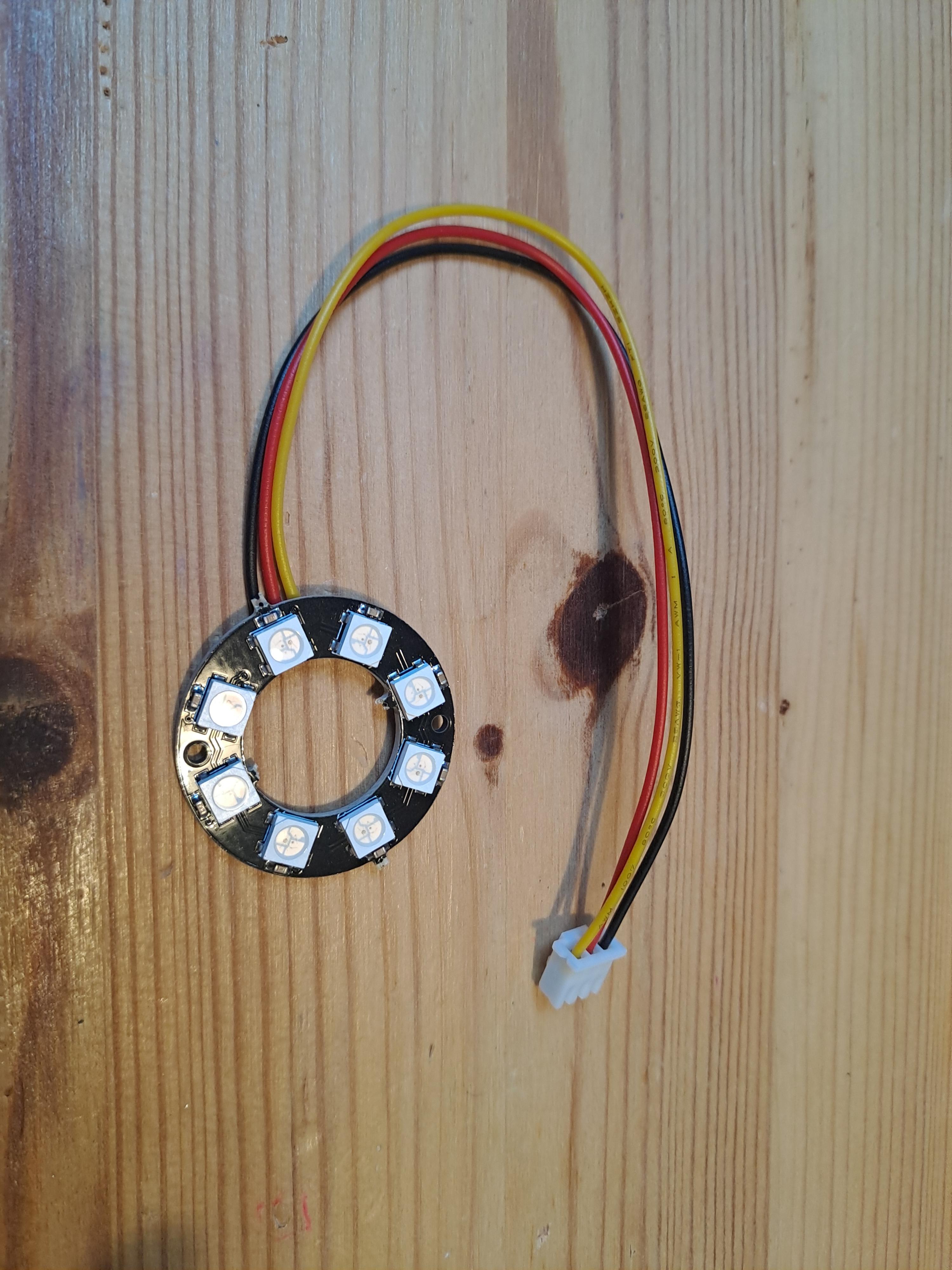
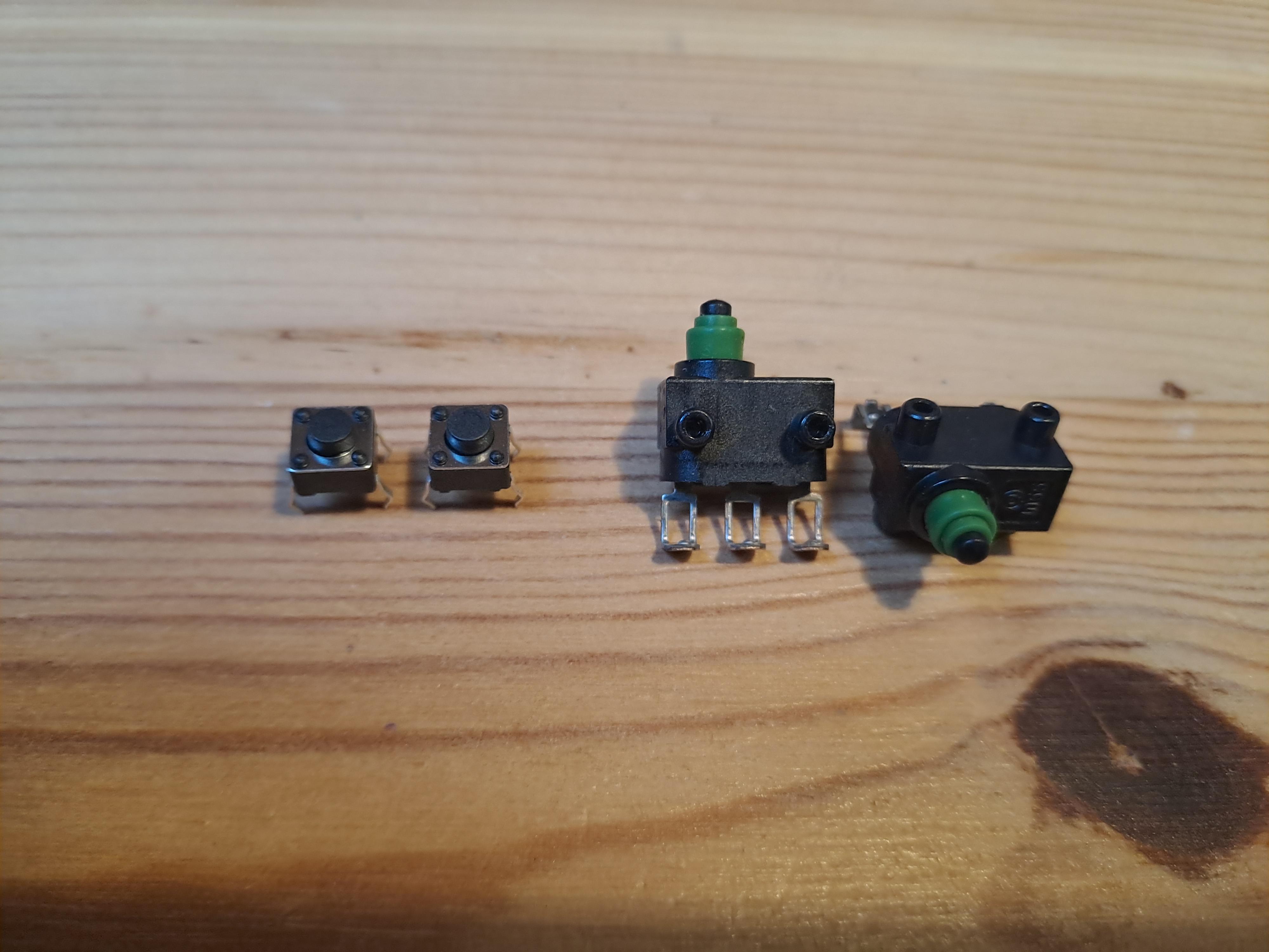
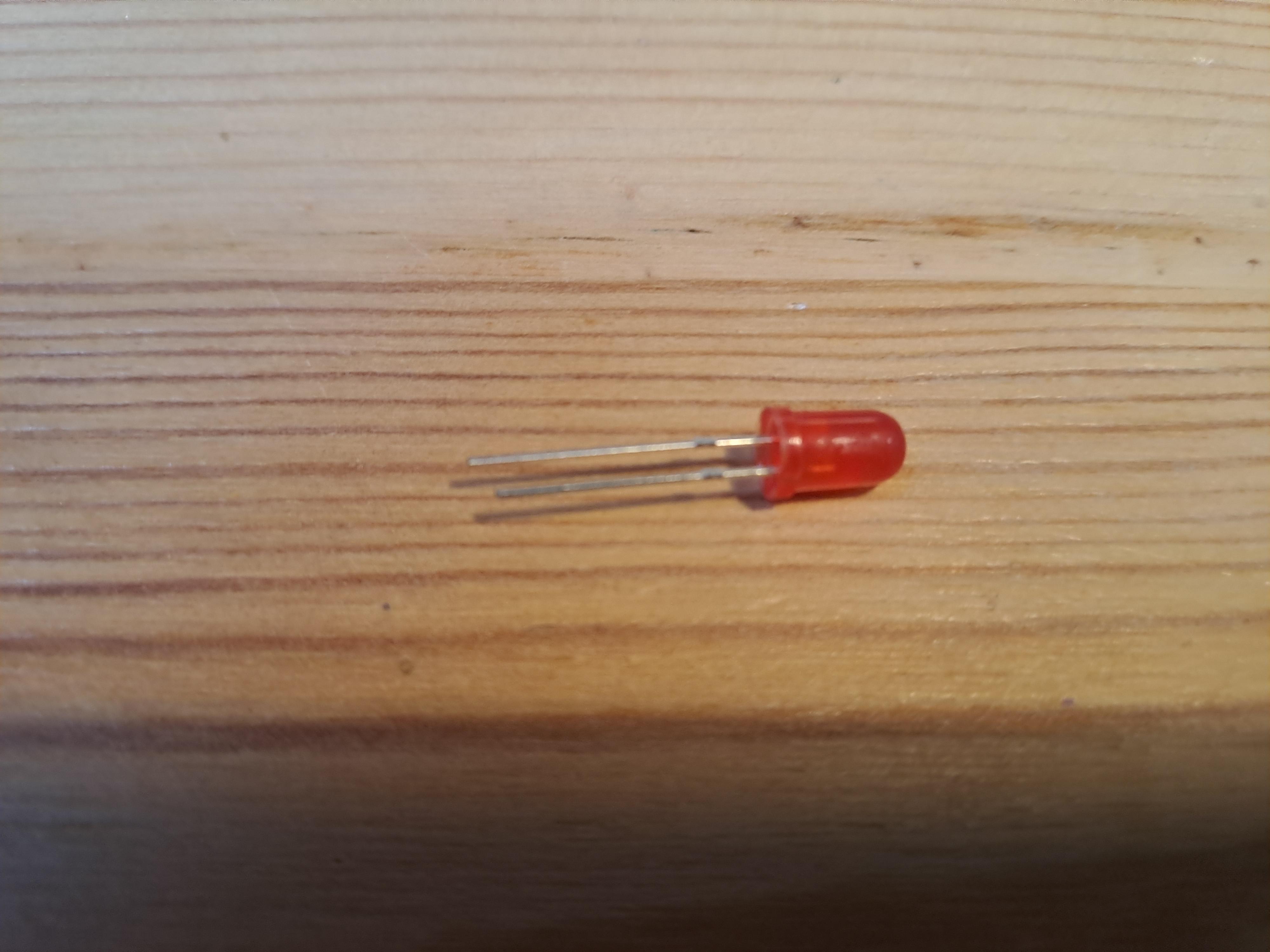
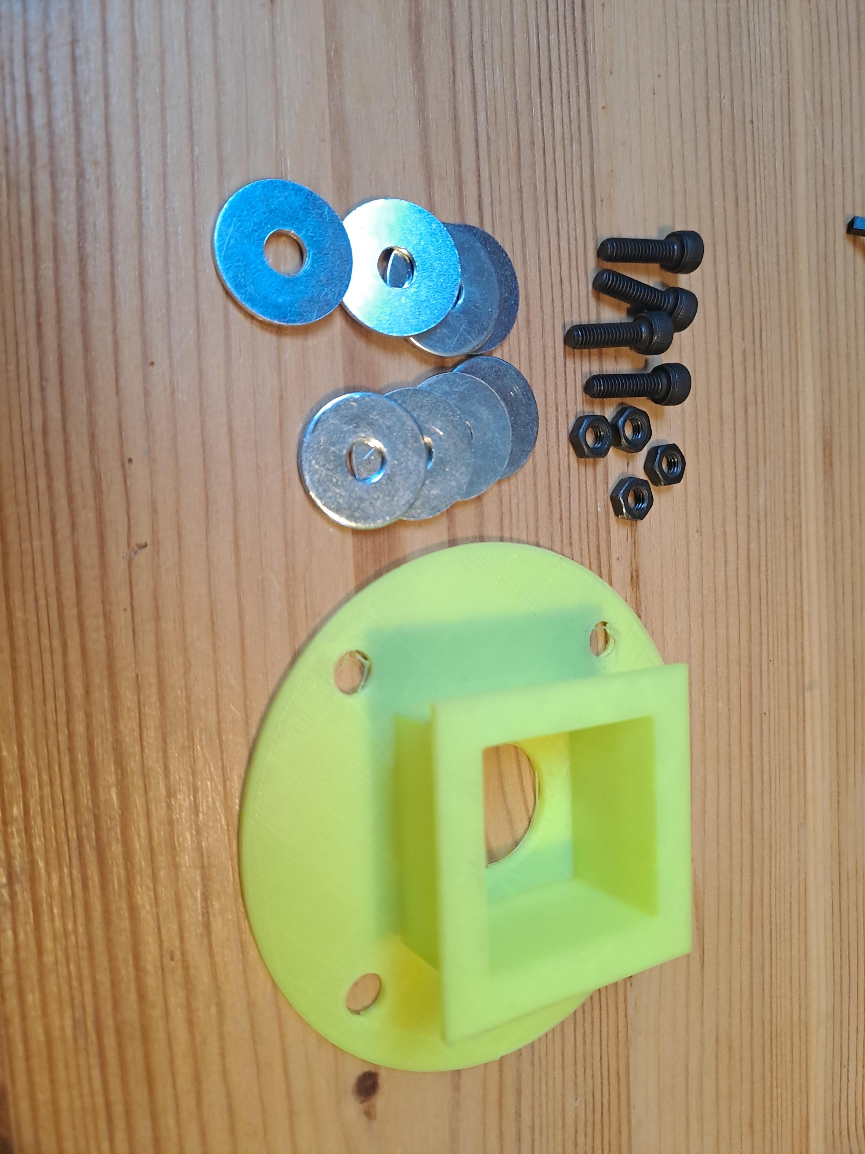
Let’s begin by reviewing the materials you’ll need before getting started. Most of the components I use are affordable and readily available from DIY electronics online stores. Many parts can be substituted with similar alternatives.
If you’re new to DIY electronics, I recommend purchasing the exact parts listed to ensure a smooth build process. However, if you have some experience, feel free to customize the shopping list to suit your preferences.
Essential Components
- 3D-Printed Parts: Download the files here. Use PETG or another durable material instead of PLA for better weather resistance.
- Teflon Diffuser Disk: 4 cm diameter, 1 mm thick.
- Powerbank: At least 10,000 mAh for extended operation.
- Jetson Nano Developer Kit (or Raspberry Pi 4 for basic setups).
- Cooling Fan: To keep the Jetson Nano running smoothly.
- Jetson Nano WiFi Module.
- MicroSD Card: 32GB or larger for the Linux image and code.
- Raspberry Pi Camera v2 and Ribbon cables (45–60 cm).
- Parallax Feedback Servos: For 360° movement (with aluminum disks).
- ESP32 Microcontroller, perf board, pin headers.
- Neopixel Ring: 8 LEDs (high-quality recommended).
- Pushbuttons: 2 required.
- Control LED: Color of your choice.
- USB stick for image storage (optional)
- Additional parts: Screws, spacers, washers, and USB cables.
Prepare Jetson Nano Image
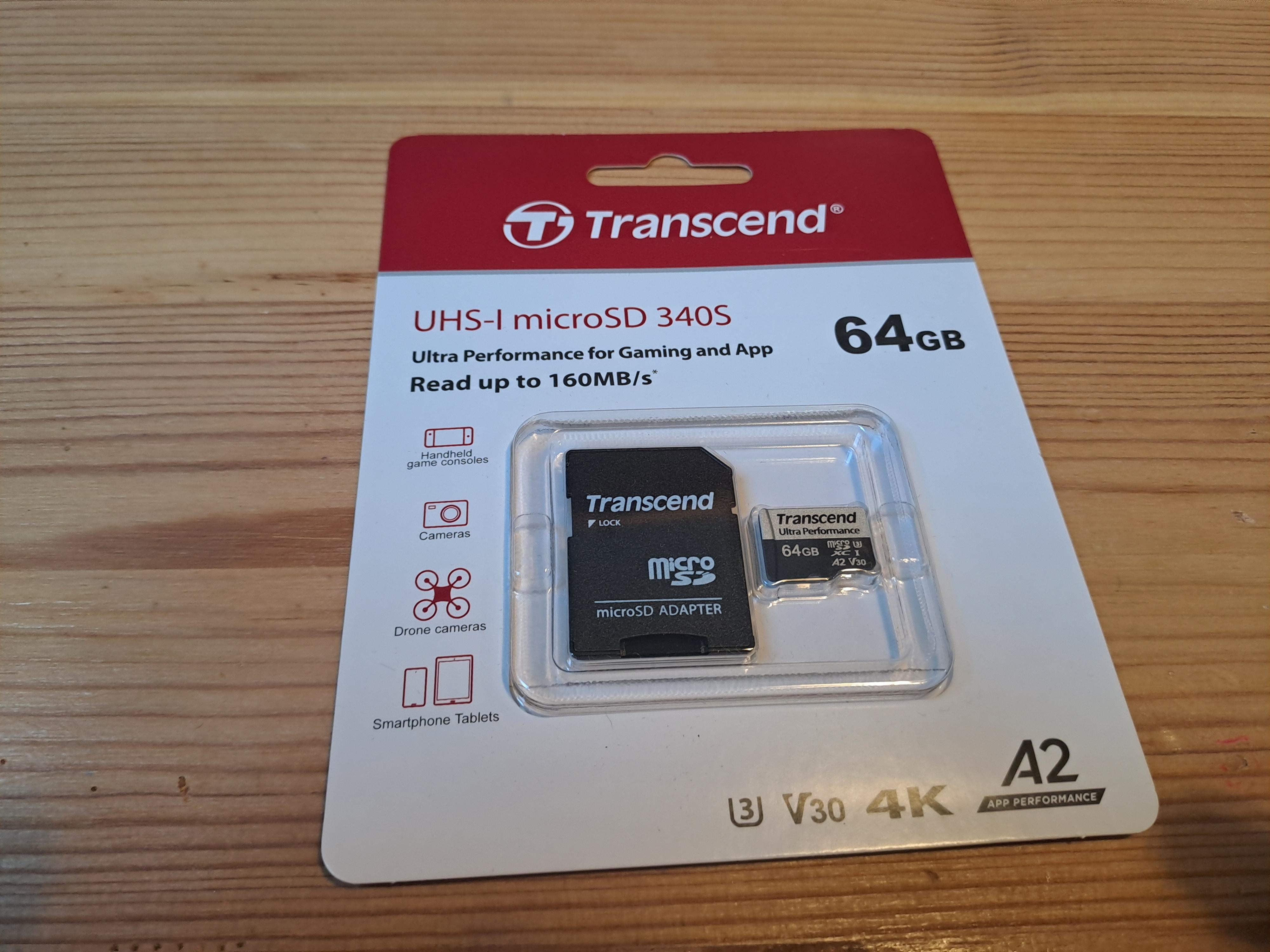
Before your Jetson Nano can start operating, we need to set up its operating system.
Here's how to prepare it:
- 🧹 Format the SD Card: Use SD Card Formatter to clean and format your SD card. Make sure it has a capacity of at least 32GB to handle AI applications efficiently.
- 🌐 Download the OS: Visit NVIDIA's official setup page and download the Jetson Nano SD Card Image.
- 🗂 Unzip the Image: Extract the downloaded file using your preferred extraction tool.
- 🔥 Flash the Image: Use BalenaEtcher to write the extracted image onto your SD card. The process is straightforward and quick!
Prepare Jetson Nano
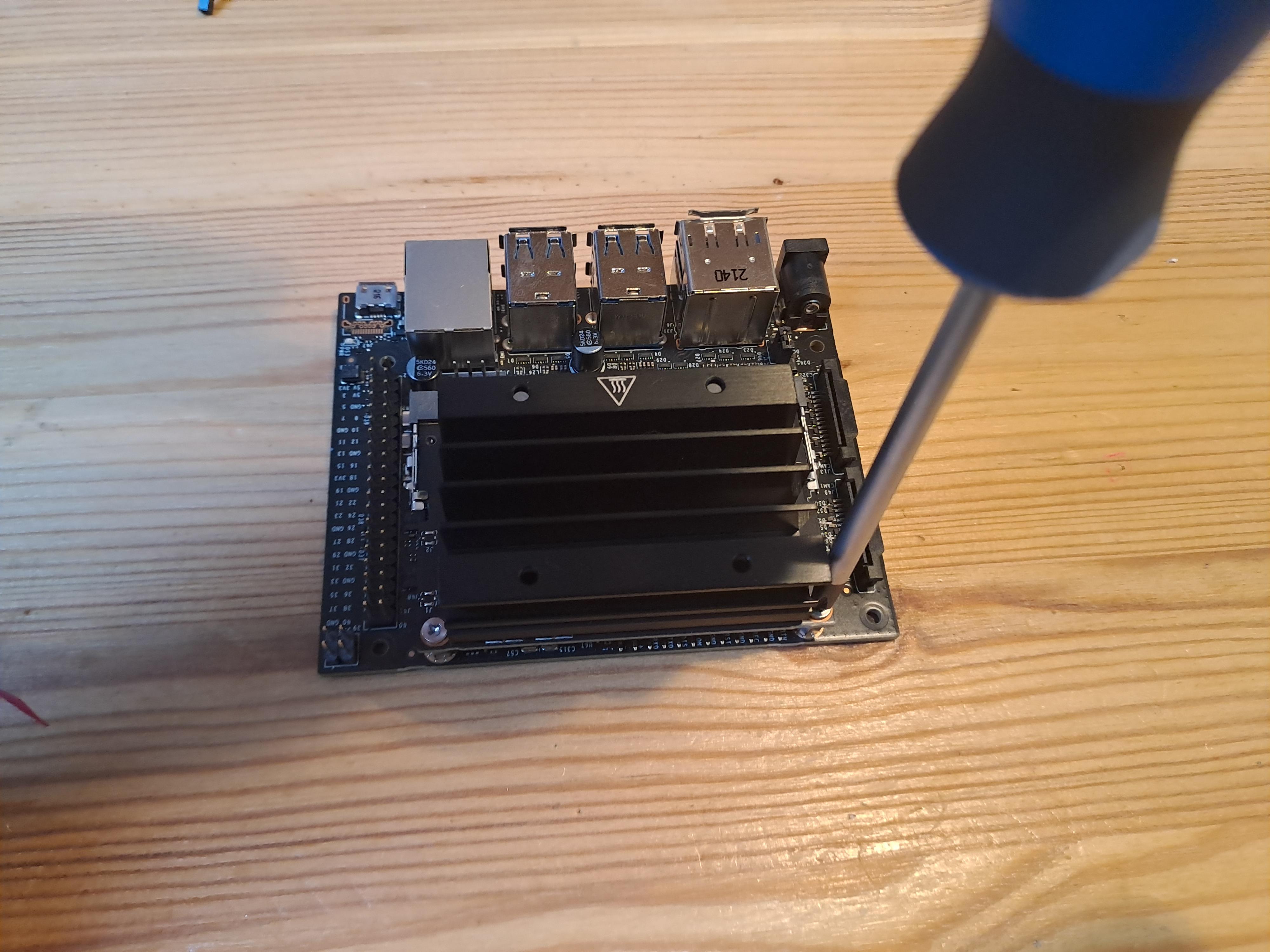
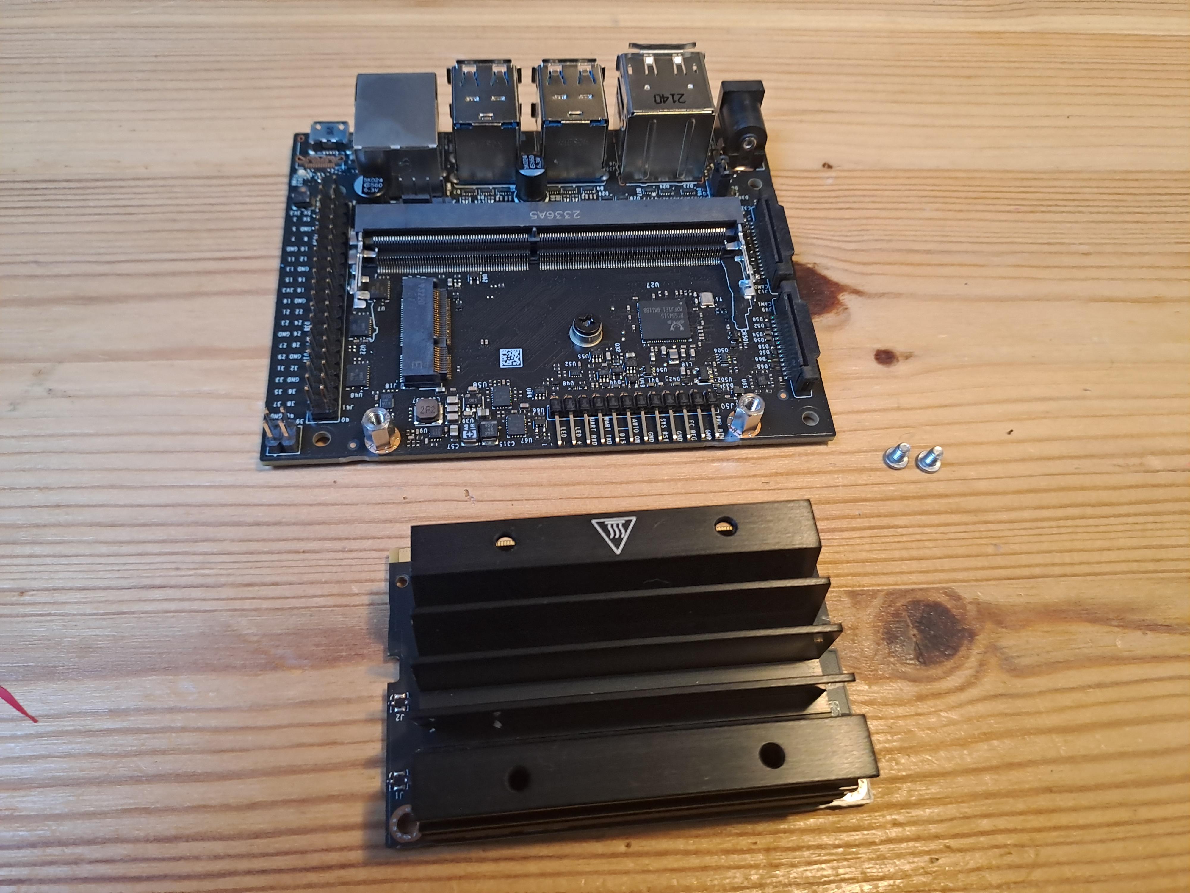
Carefully remove the heat sink with a screw driver, ensuring no screws are lost.
Add Wifi Module
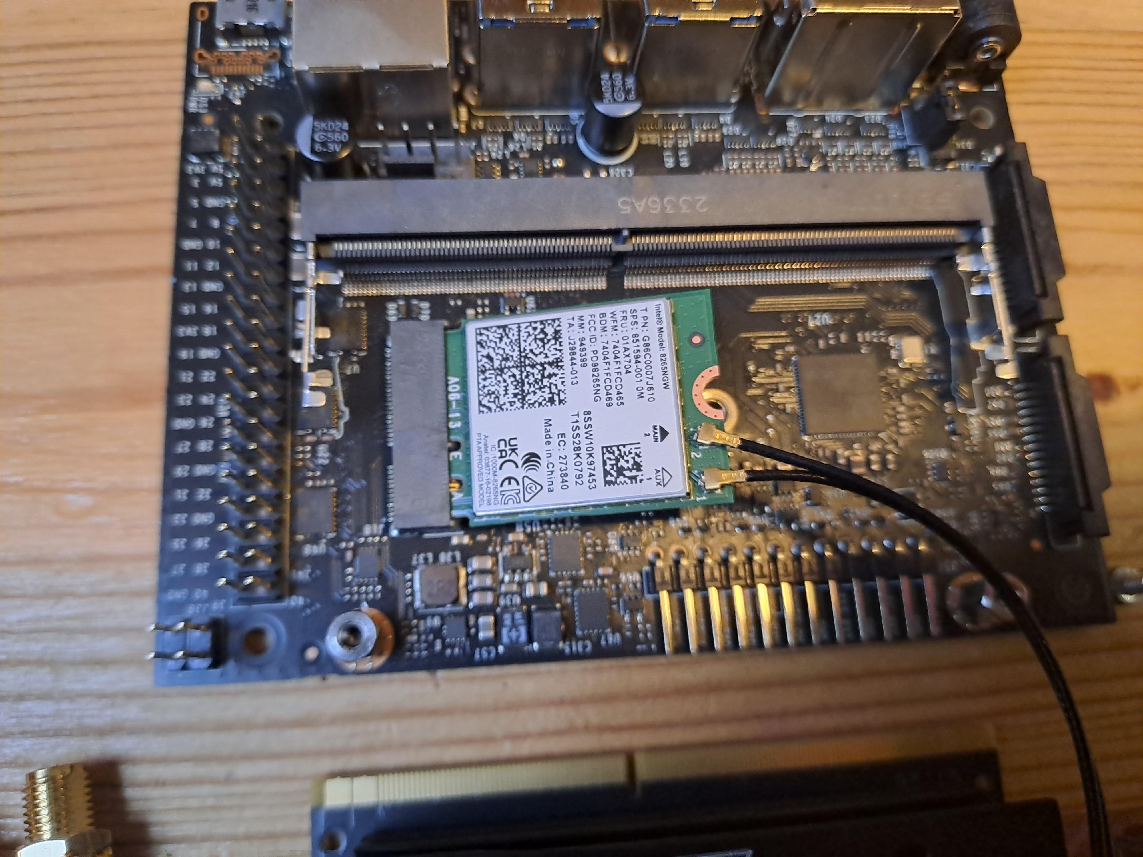
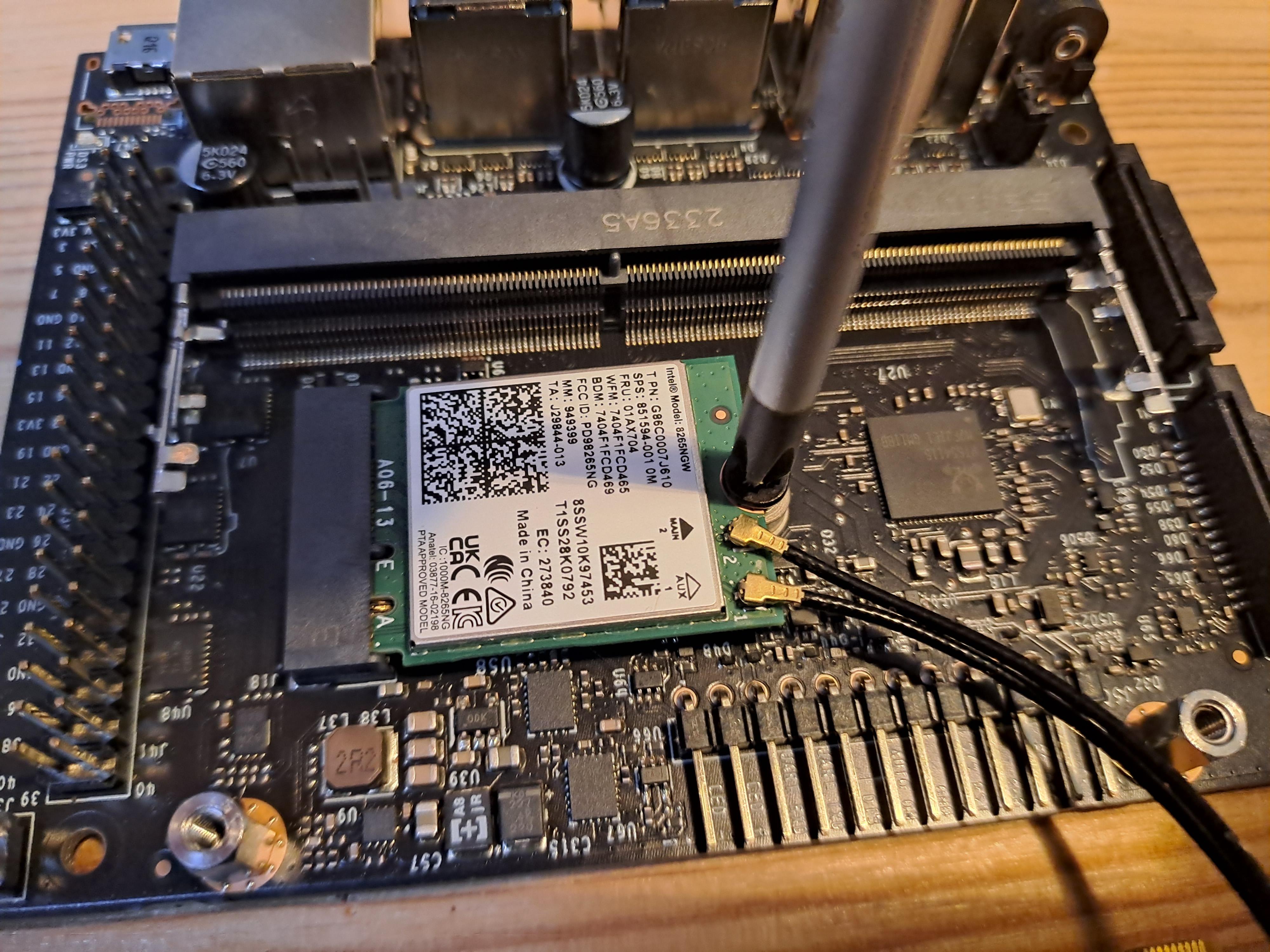
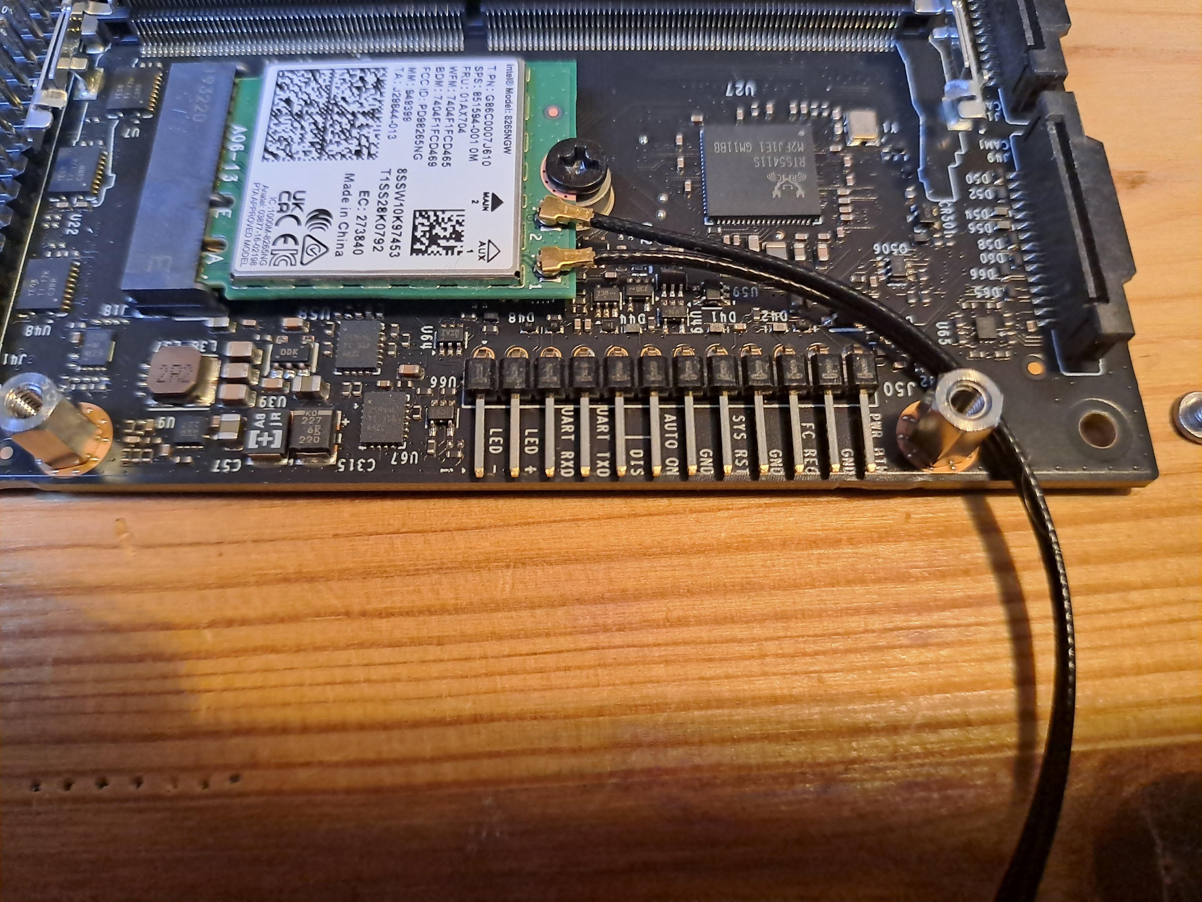
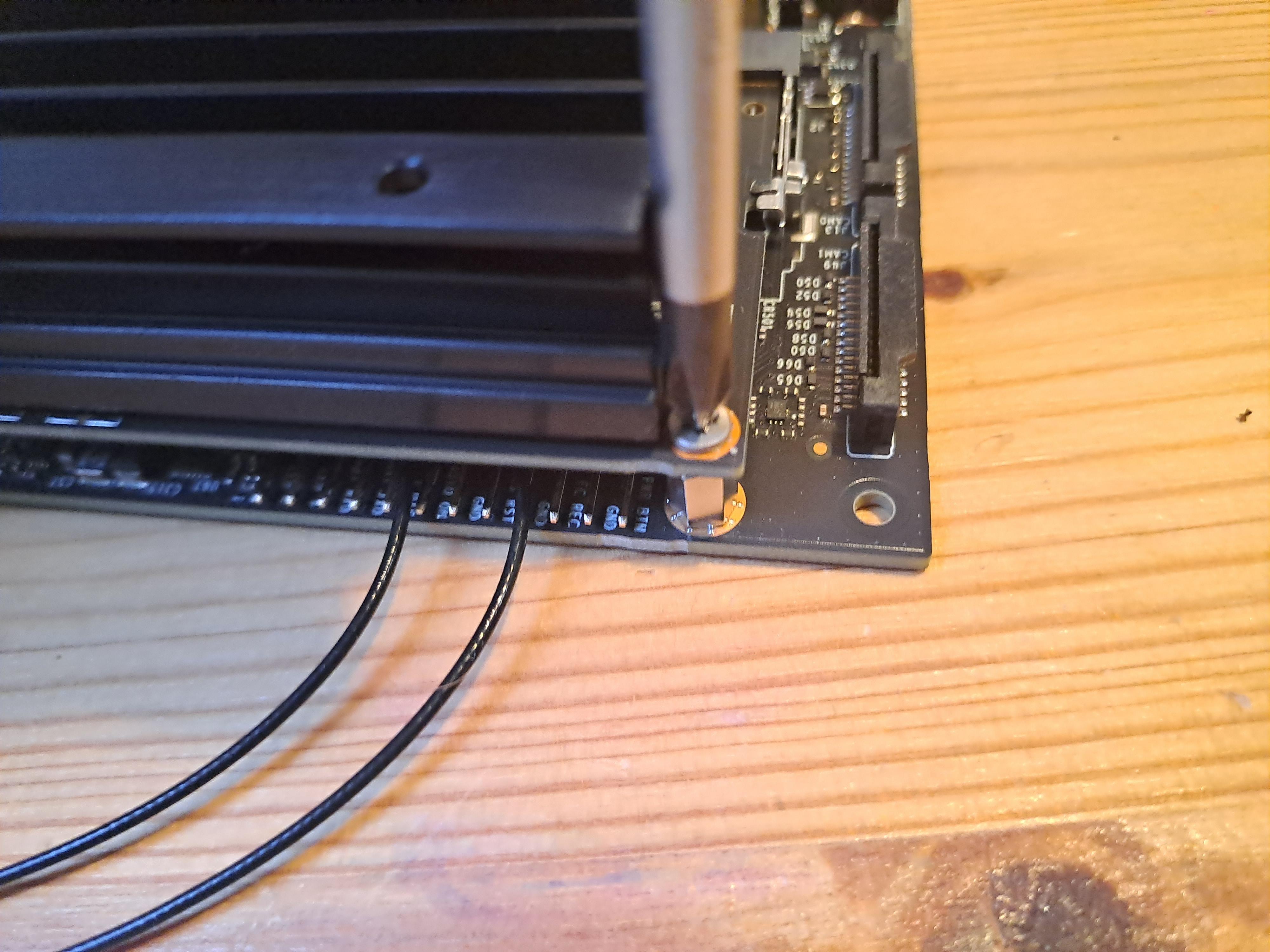
To add the WiFi Module:
- Remove the black screw beneath the heat sink
- Carefully slide the WiFi module into place. No force is required. Be careful not to damage it!
- Secure the module with the black screw without over-tightening.
- Attach the antenna cables
- Reattach the heat sink.
Add Cooling Fan
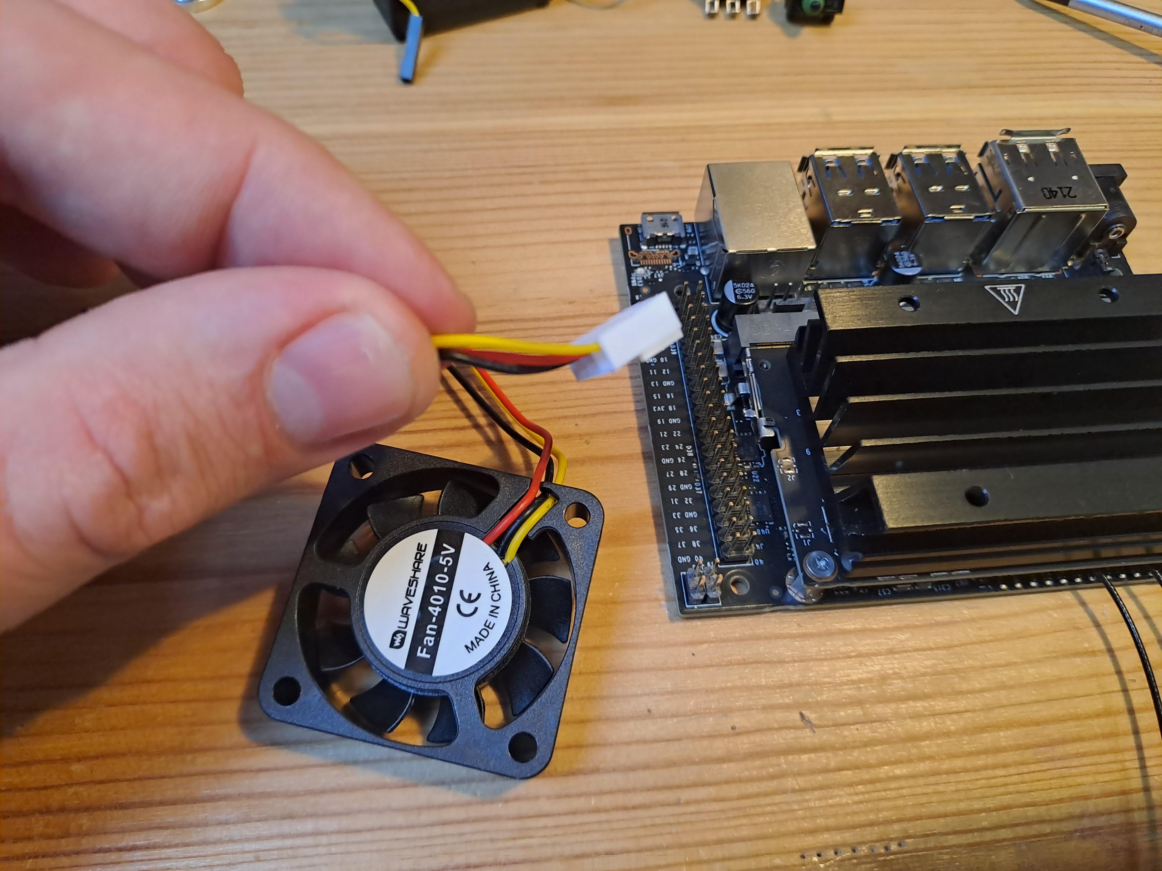
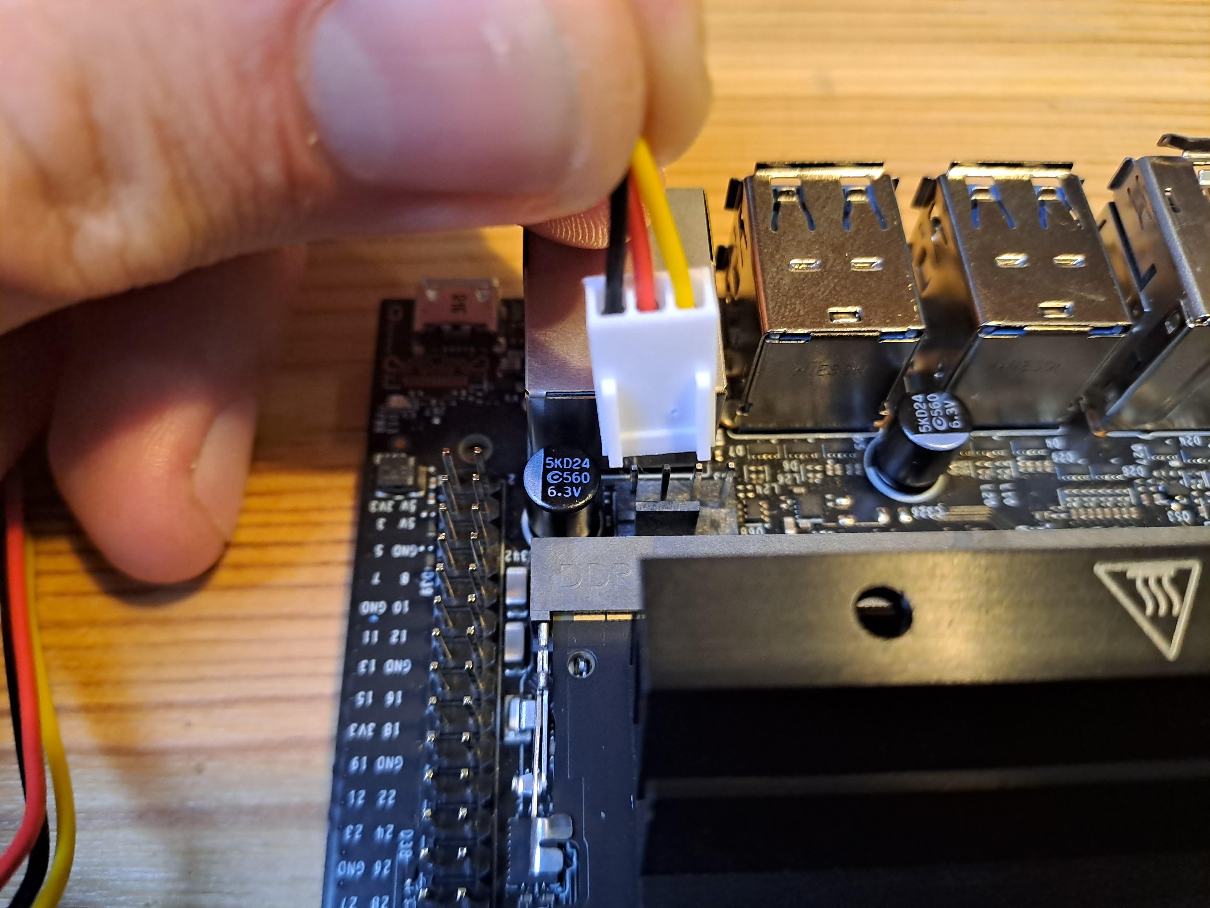
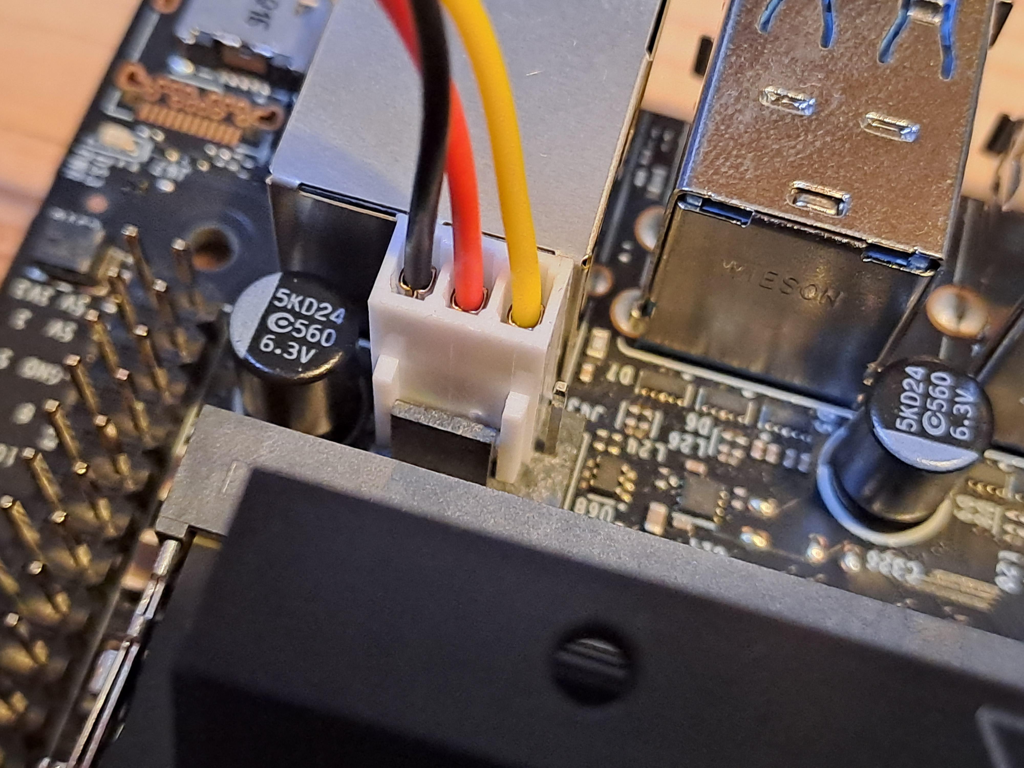
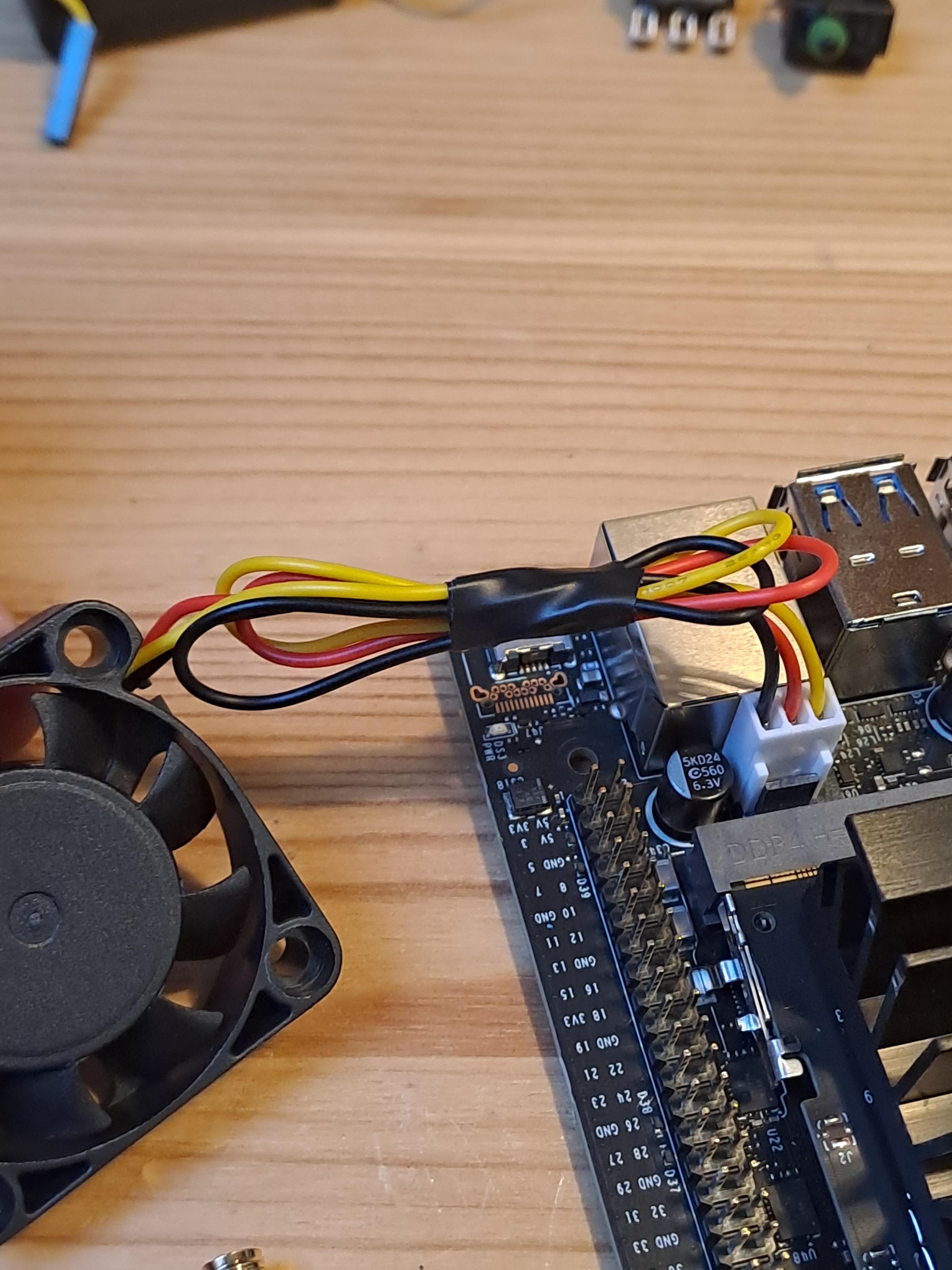
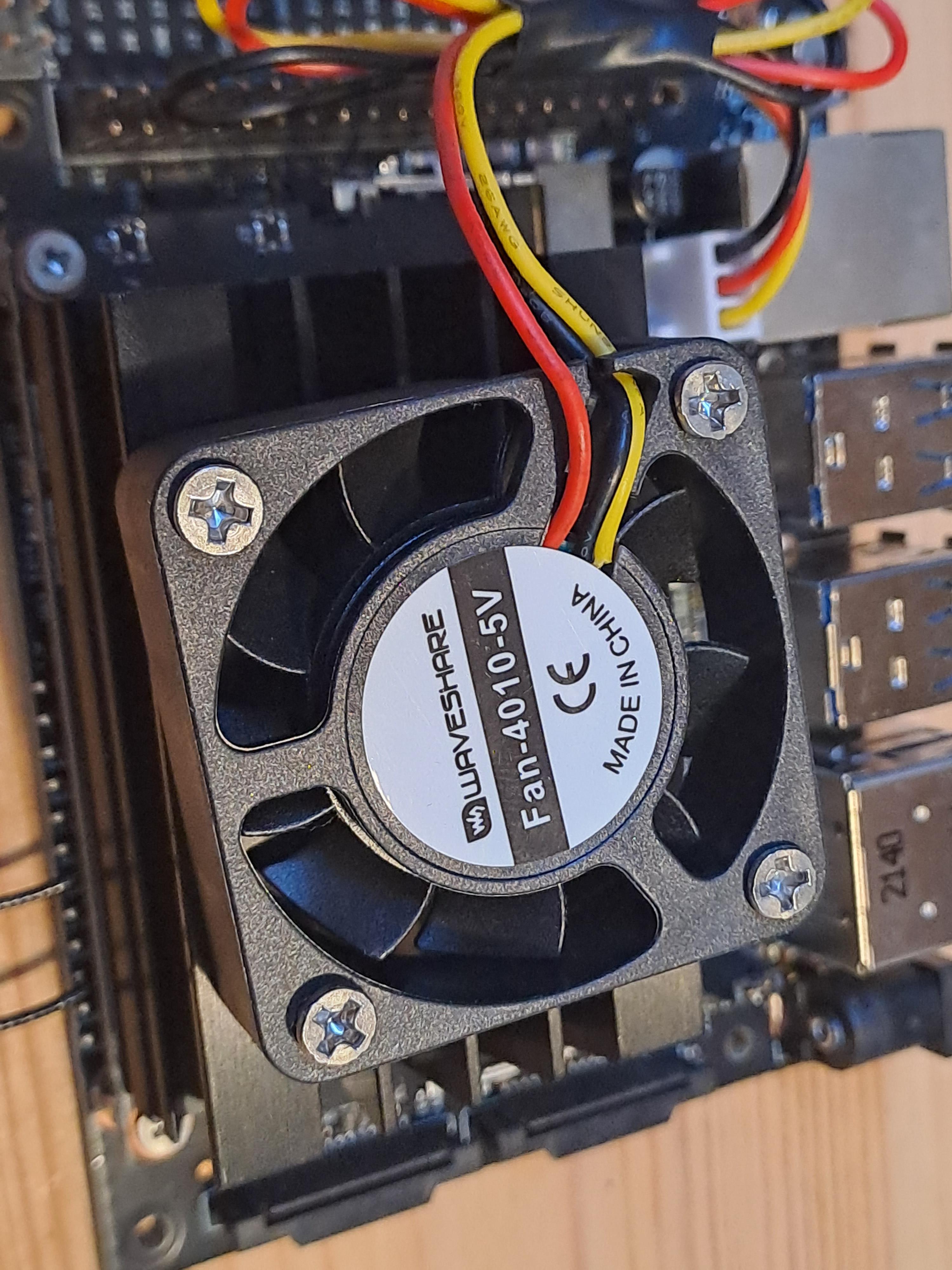
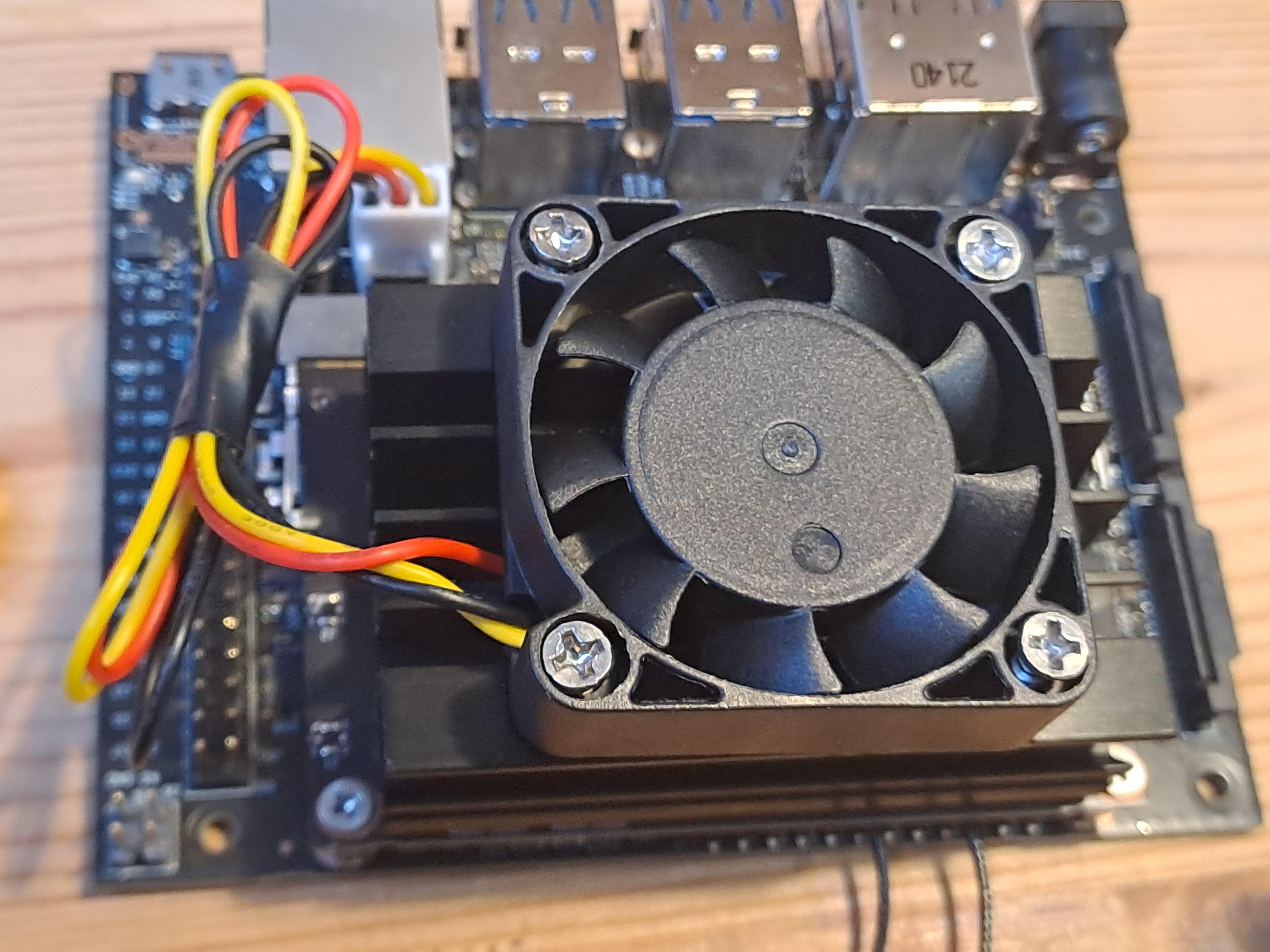
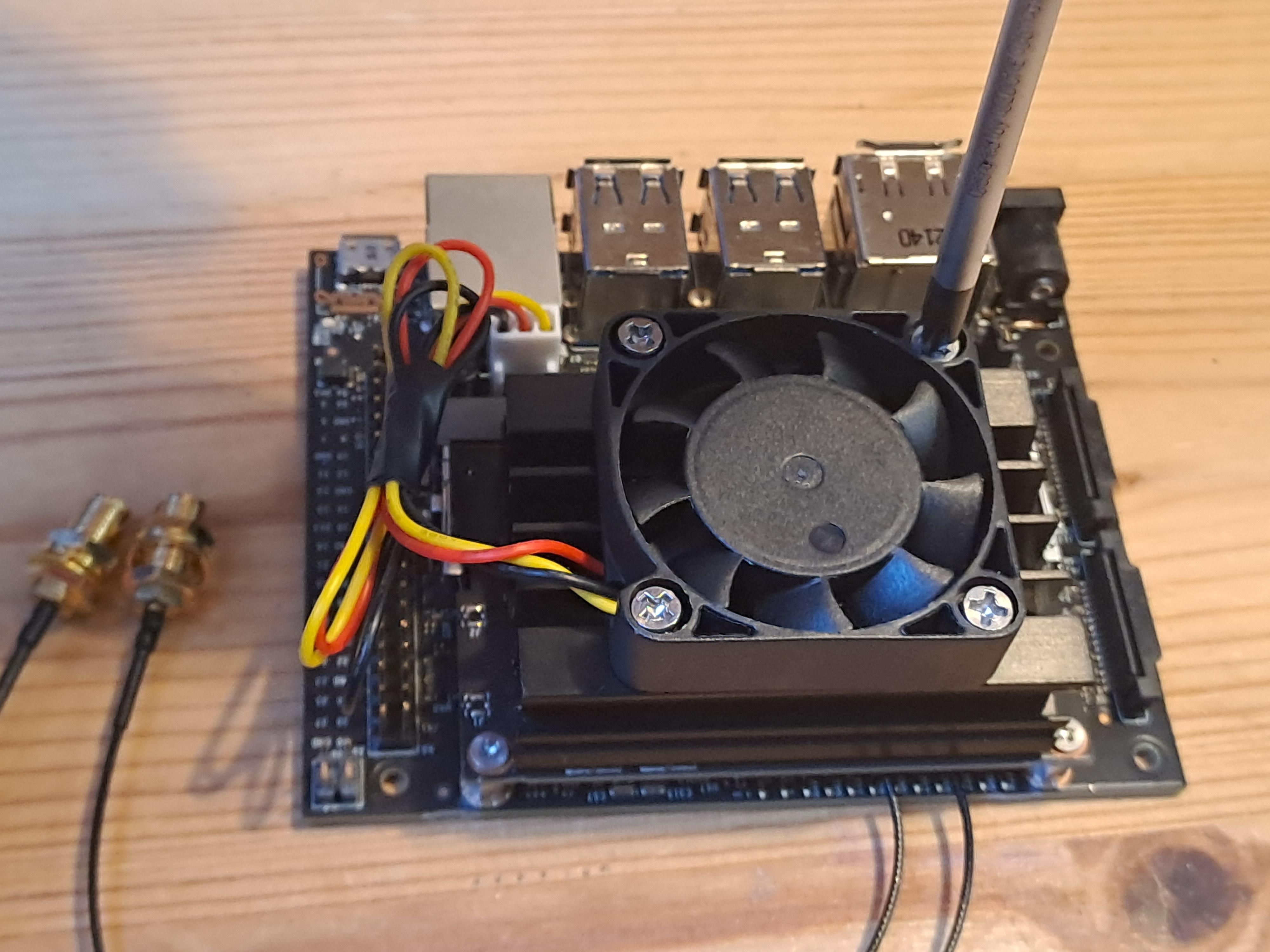
Now let's add the cooling fan:
- Connect it to the Jetson Nano fan socket (review the pictures above).
- Mount the fan onto the heat sink.
- Secure the fan with screws; most fans (even the original one) come with horrible wood screws. Ideally replace them with machine screws and counter nuts.
- Tape or route the cables neatly to avoid interference.
Let's Start the Jetson Nano for a First Time
Now we can start the Jetson nano for a first time:
- 💾 Insert the SD Card in the slot under the heat sink.
- 🖥 Connect Peripherals: Hook up a screen via HDMI, a mouse, and a keyboard via USB.
- ⚡ Power Up: Add a jumper for 5V and connect power via the barrel jack.
- 🚀 Boot Time: Your Jetson Nano should come alive!
Initial Setup for Jetson Nano
Welcome to the Nano interface! Set up the system:
- Accept the license.
- Choose your language, keyboard layout, and time zone.
- Enter your name (I use "vt360"), set a password (I use e.g. 1234, which is not very safe as you can imagine), and enable auto-login.
- Keep the app partition size as default.
- Select the MAXN option for maximum power (this is not very energy efficient but helps to generate on board mosaics, if you generate the mosaics/panoramas on another computer you can also select the other option).
- Reboot and watch the desktop load.
Remote Control Your Jetson Nano
You might have noticed that the mouse, keyboard, and monitor cables are cumbersome and will obstruct the camera’s rotation. To keep things tidy and functional, let’s set up remote access. You’ll need an Ethernet cable for the initial setup, and later, you can switch to WiFi.
Here’s how to get started:
On the Jetson Nano:
- 🖥 Ethernet First: Plug in an Ethernet cable (weirdly, this activates WiFi connectivity later).
- 🔄 Restart: Restart the Nano and connect to WiFi.
- 🌐 Open Chromium: Navigate to this VNC setup guide.
- 🛠 Configure VNC: Open a terminal and run these commands (I use the password '123456' here which is of course absolutely not safe):
- 🔍 Find Your IP: After reboot, type ifconfig in the terminal to get the Nano’s IP address (e.g., 192.168.1.198).
On Your Computer:
- 🖥 Install VNC Viewer: You can download it here. Open it and type in the Nano’s IP address.
- 🔑 Enter Password: Use the password 123456 (I hope you found a better one).
- 🎉 Connect: You’re in!
Install Spyder IDE (optional)
The Nano is great for coding, so let’s install Spyder (this is optional but I recommend it if you want to further develop this):
- 💻 Install via Software Manager: Search for "Spyder" and install it.
- 🧪 Install Python Packages: Open a terminal and run:
- 🔄 Switch Python Kernel: In Spyder, go to Tools -> Preferences -> Python Interpreter.
- Select "Use the following Python interpreter".
- Apply and OK.
Prepare Control LED
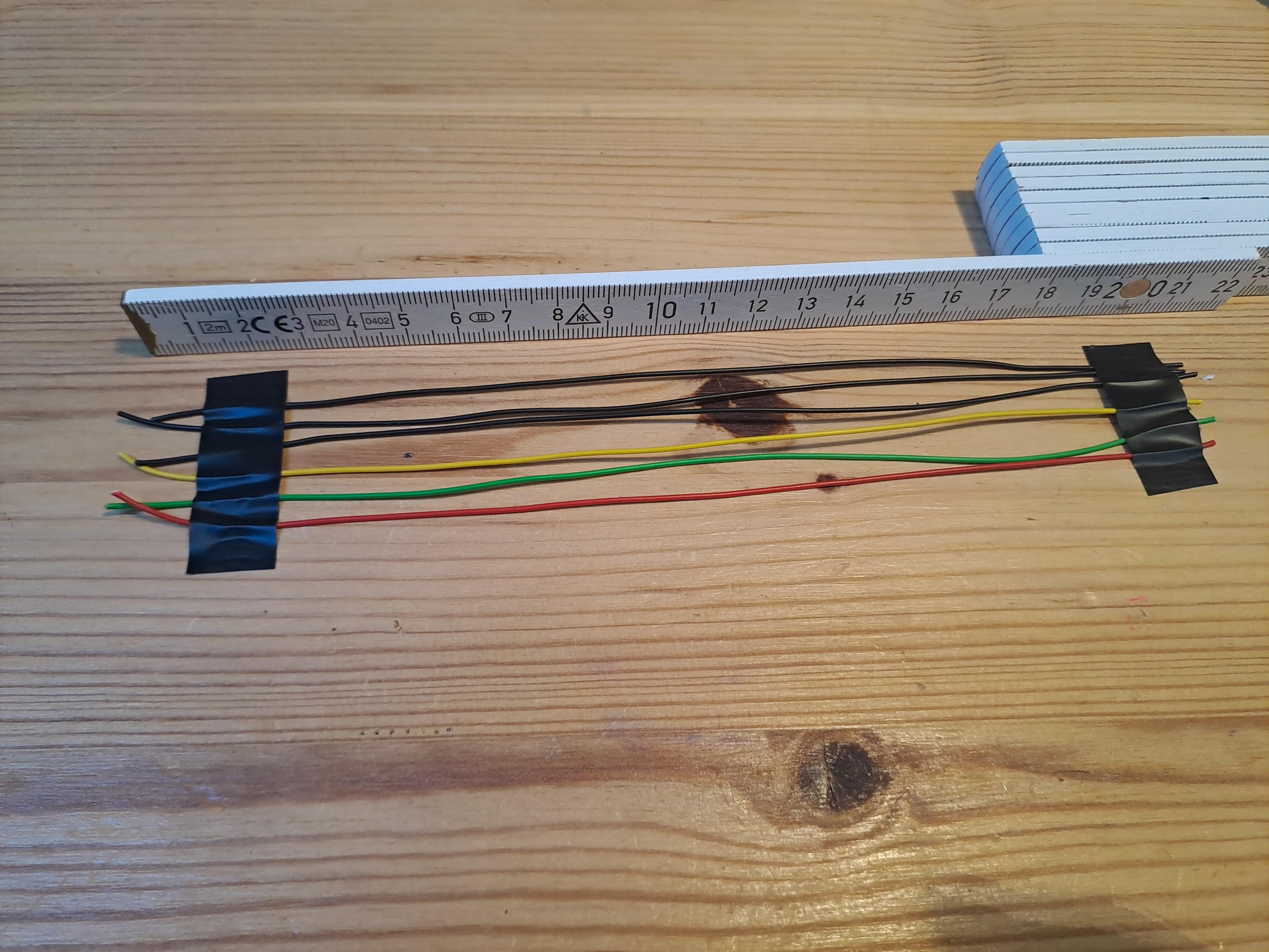
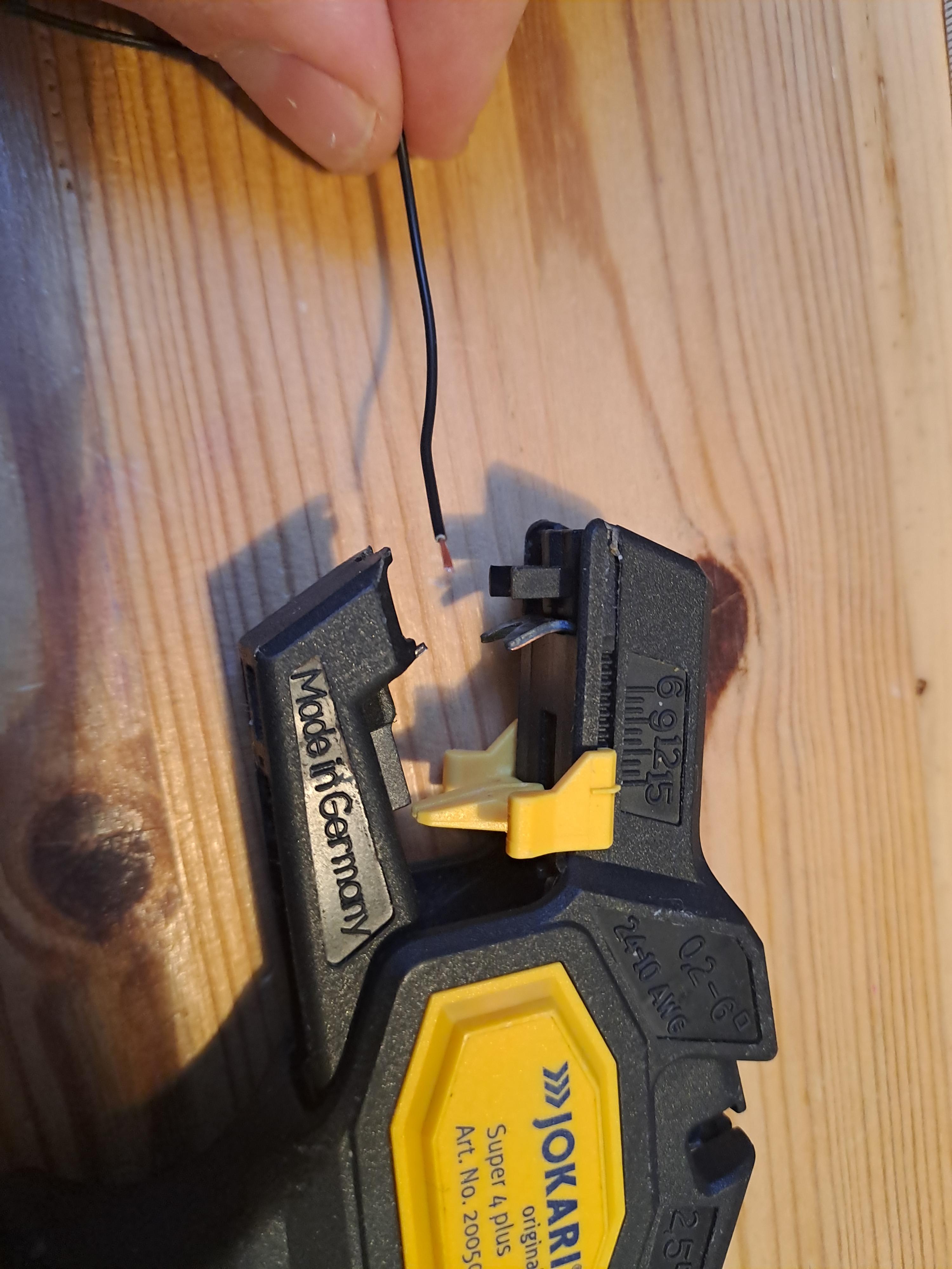
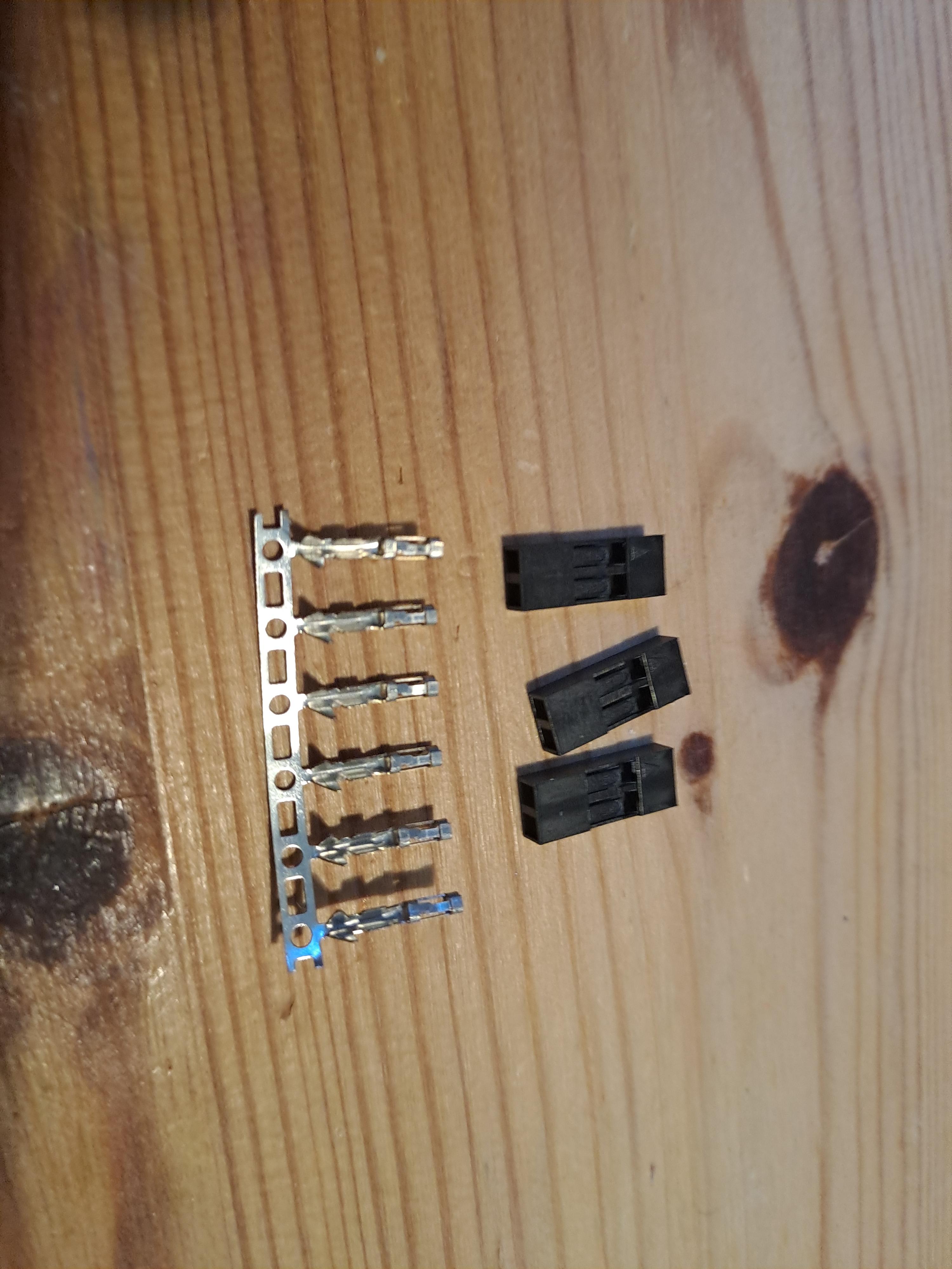
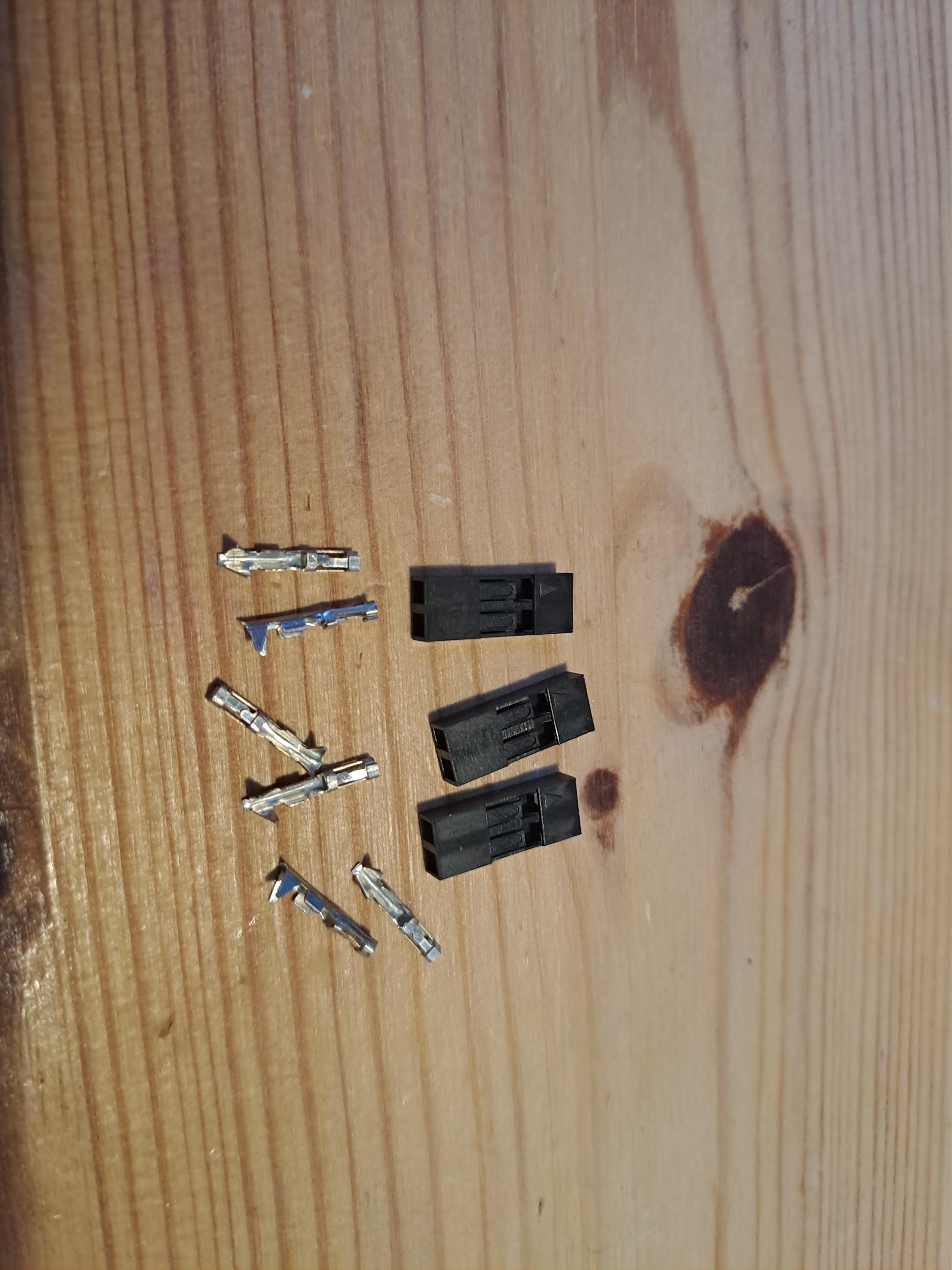
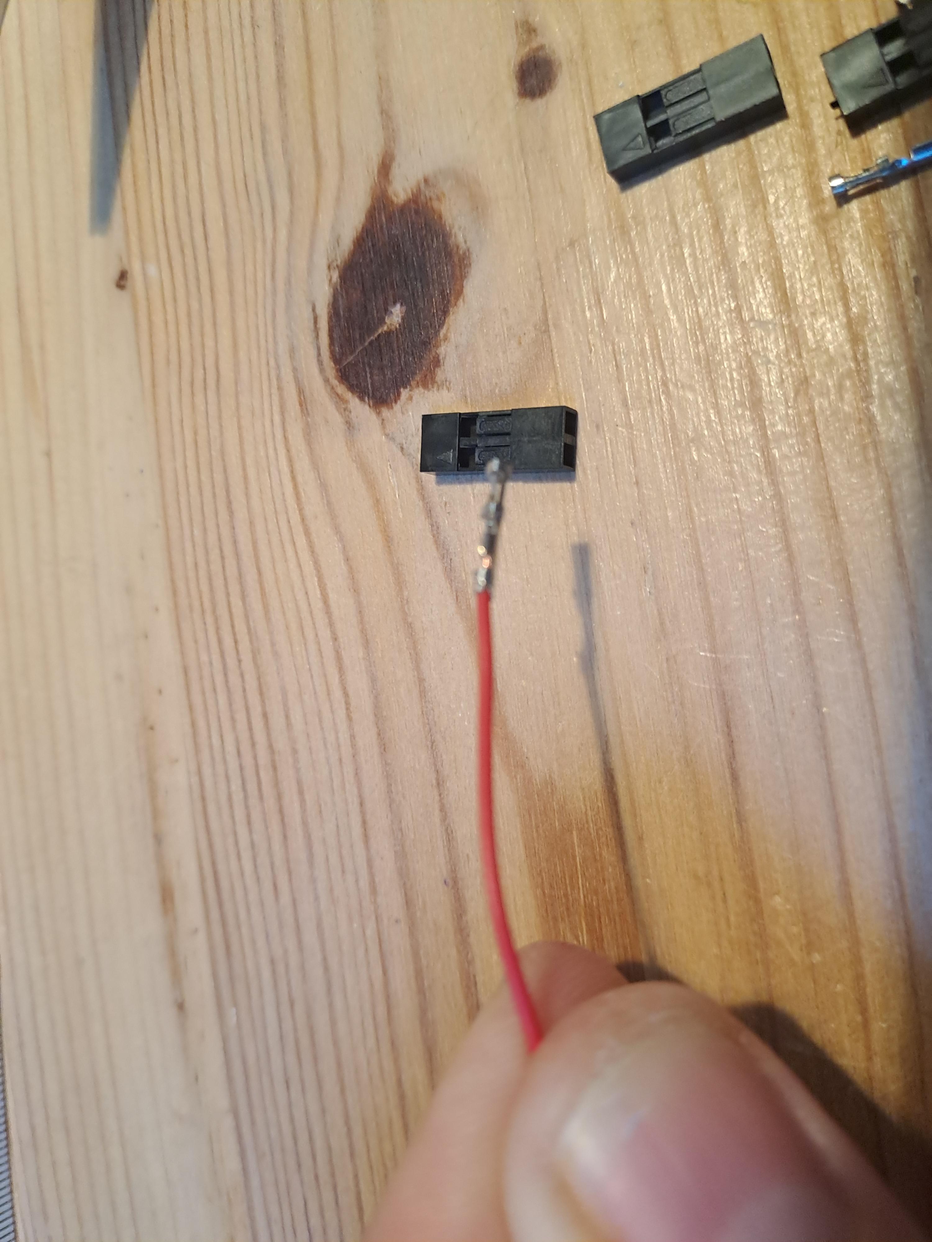
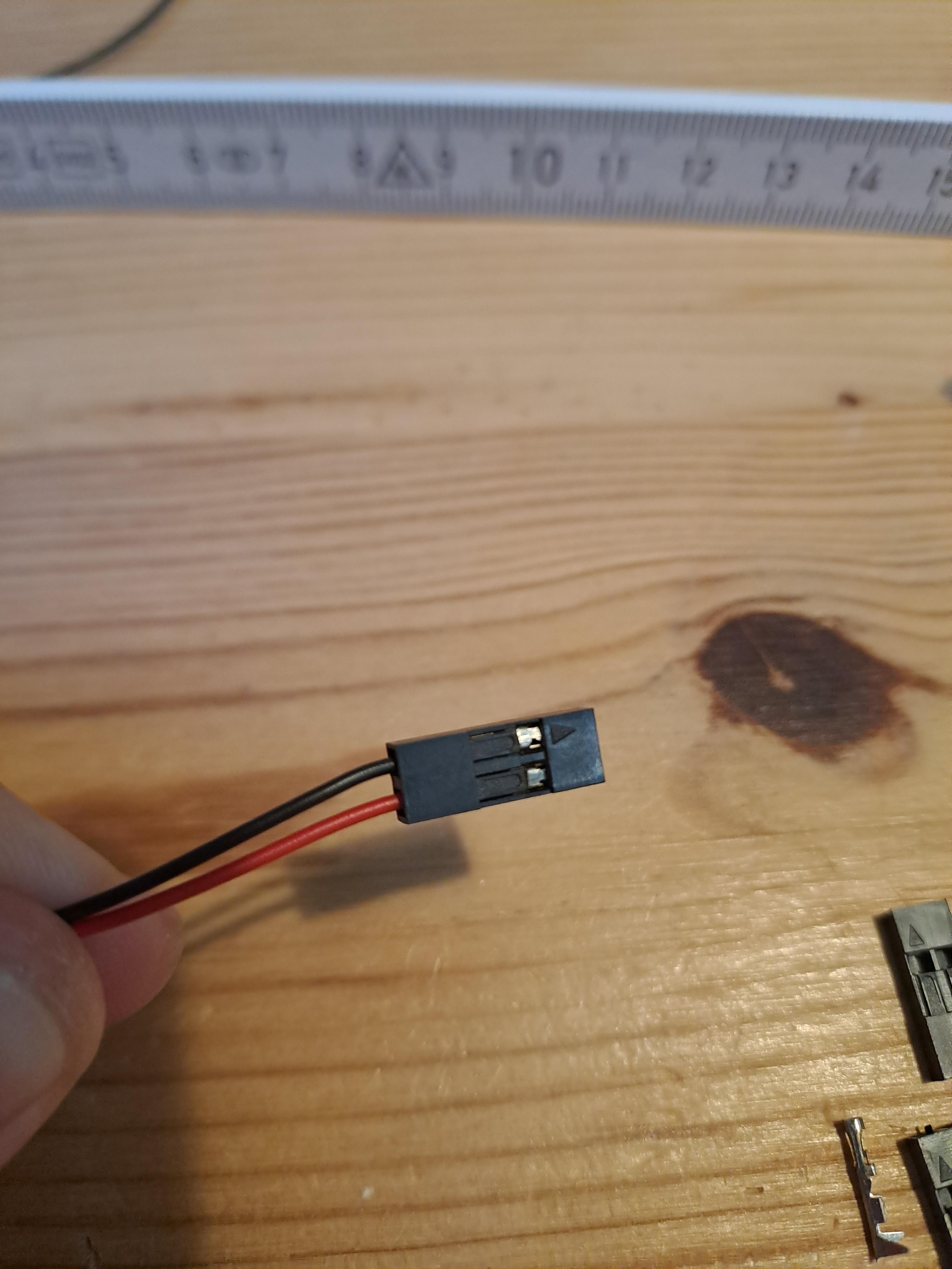
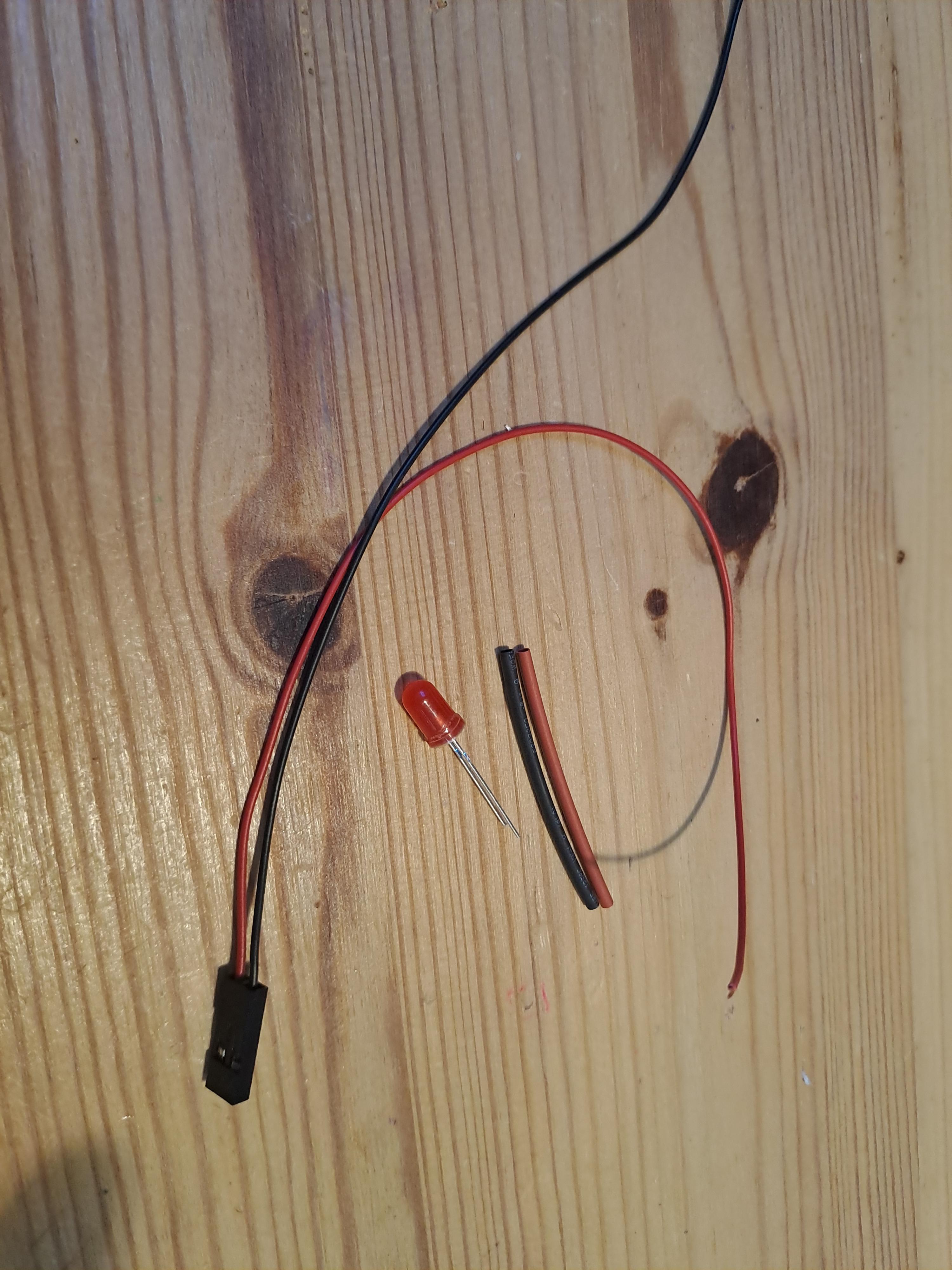
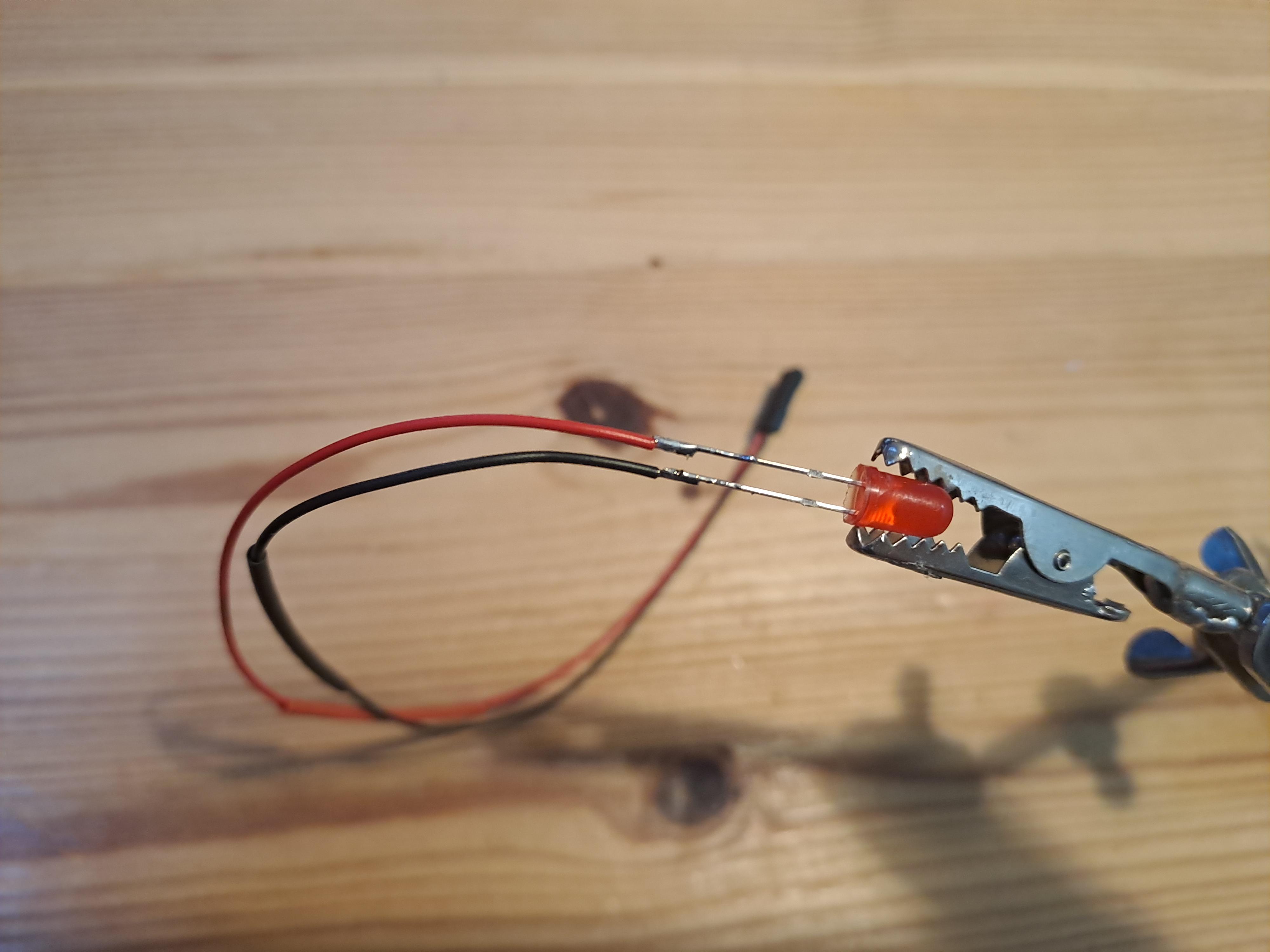
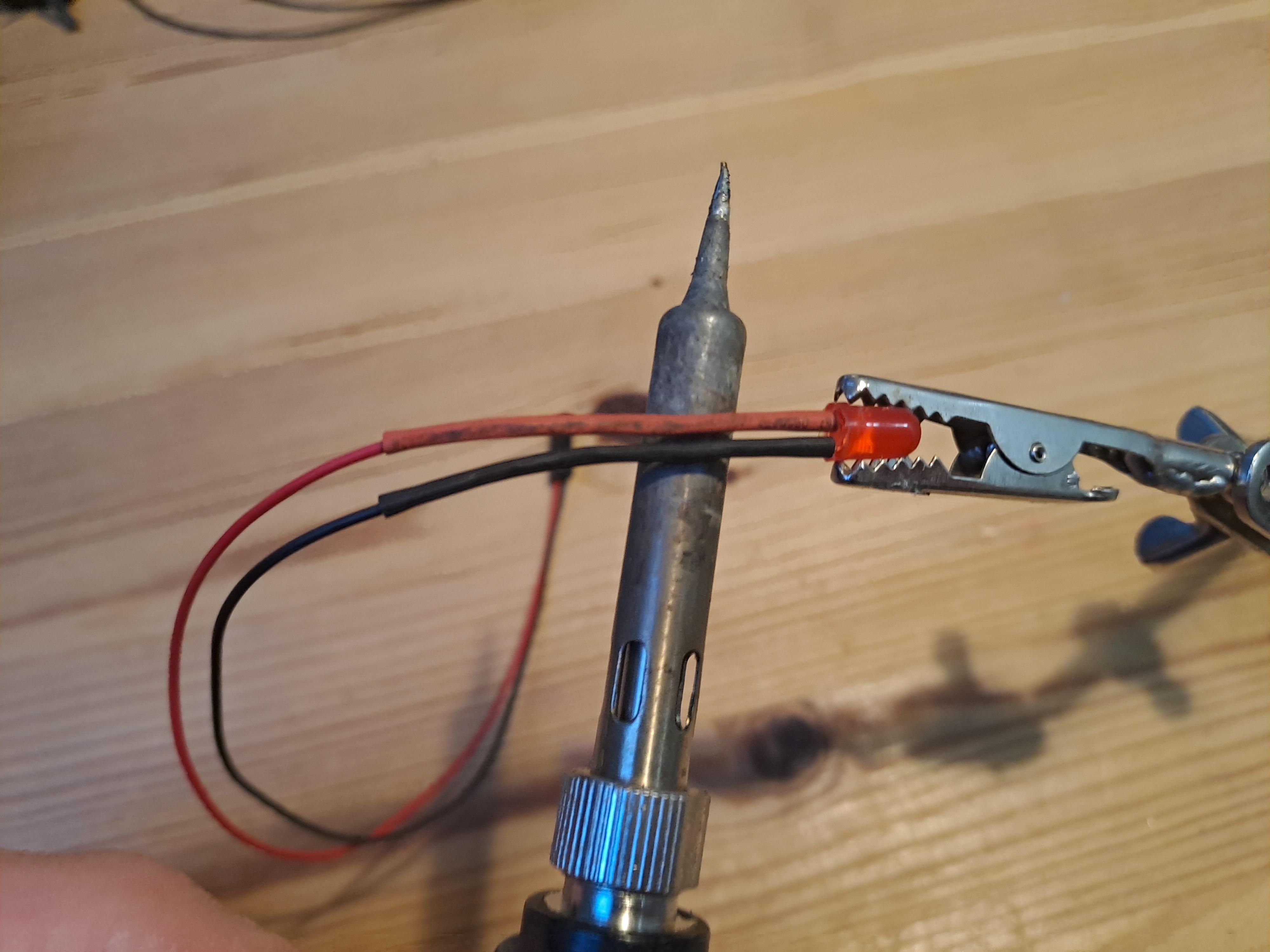
Let's prepare the control LED. This LED displays the status of the Jetson Nano (on/off/busy):
- Cut two 20 cm cables (black for ground, a colored one for the signal. Obviously, the color of the cables doesn't matter, but it helps if you have reconnect things in the field later).
- Remove the cable cover on both ends.
- Solder or clamp the cables to connectors and use heat shrink for insulation.
Prepare Control Buttons
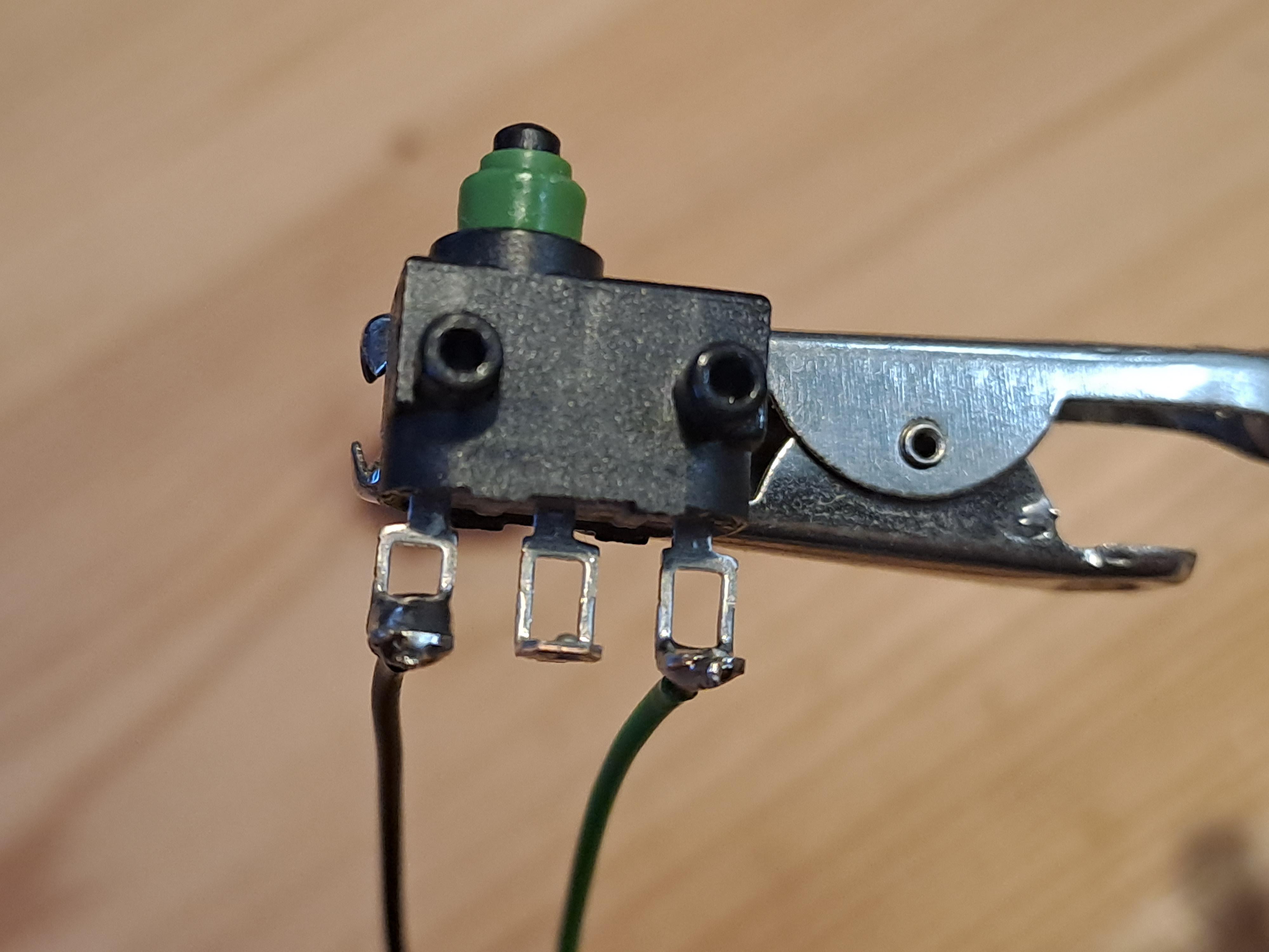
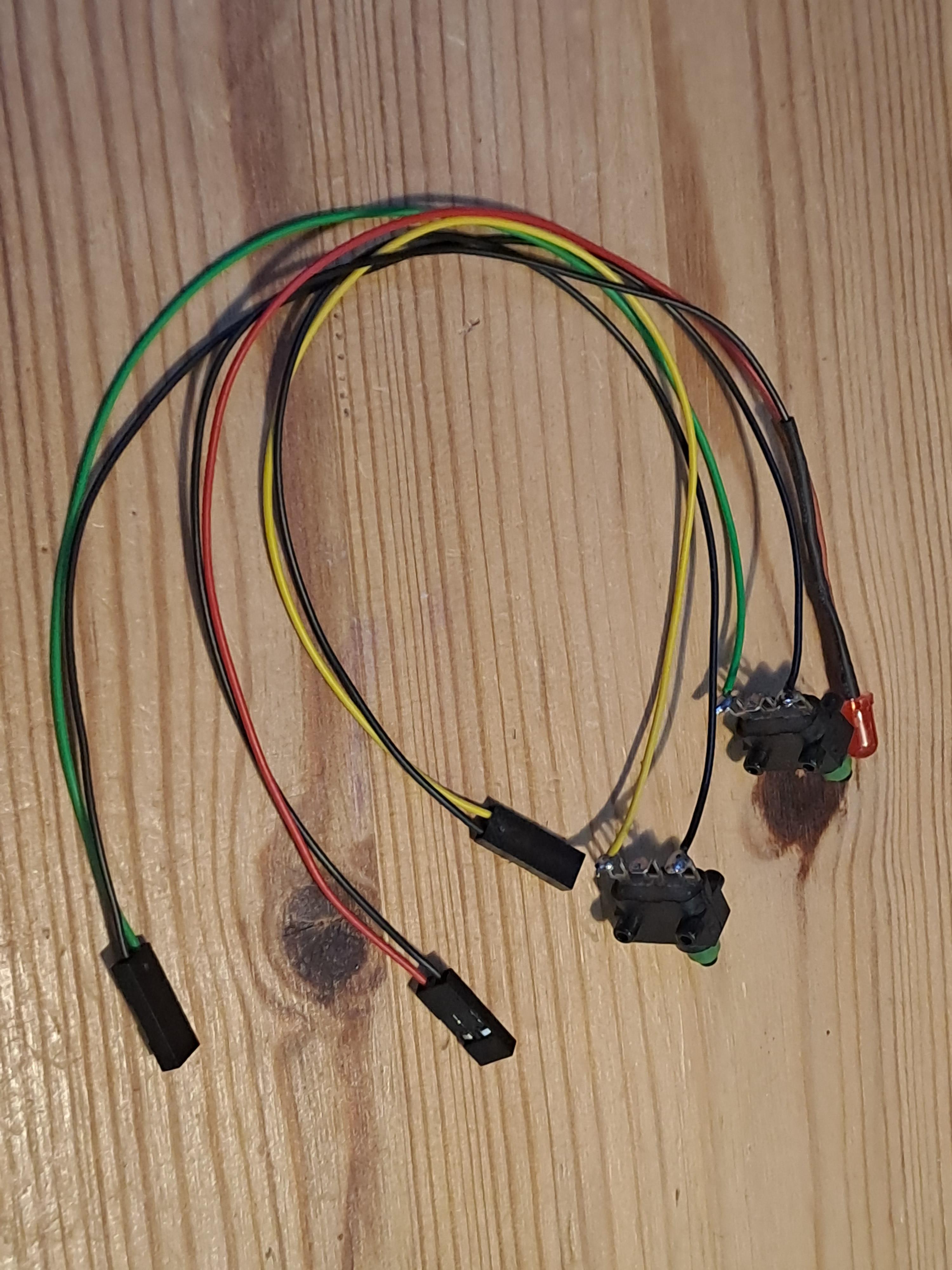
Let's now prepare the control buttons. With these buttons we can switch the Jetson Nano on and off and we can reboot the system. This is a bit more elegant and healthier to your SD card then just pulling the plug:
- Cut four cables (two black for ground and two in a different color for signals), each 20cm.
- Add connectors and heat shrink as done with the LED.
- You can use any type of pushbutton here. I really don't like the haptics of the cheap ones though. That is why I use these really nice ones from the 80ies.
Add Controls to Jetson Nano
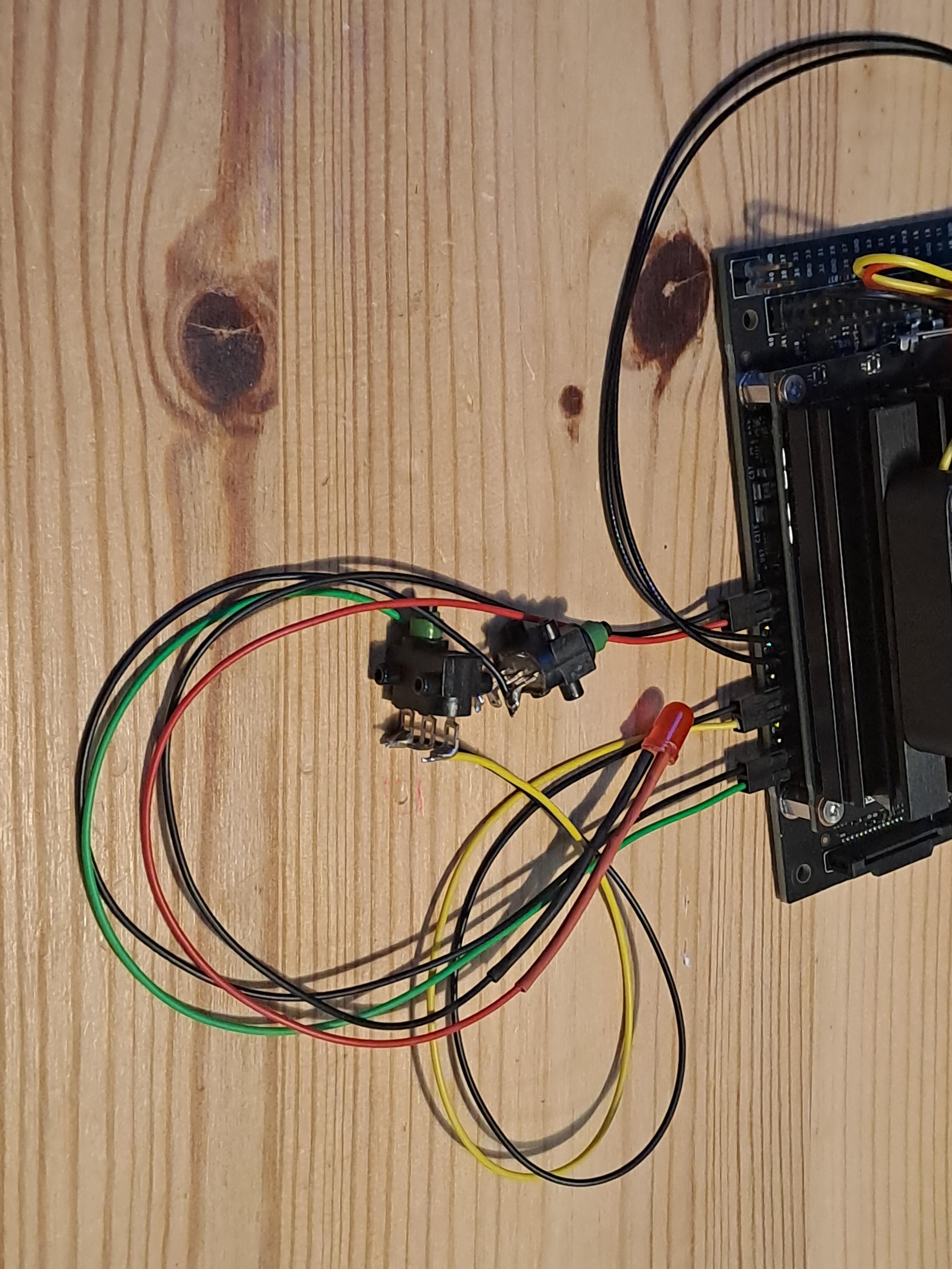
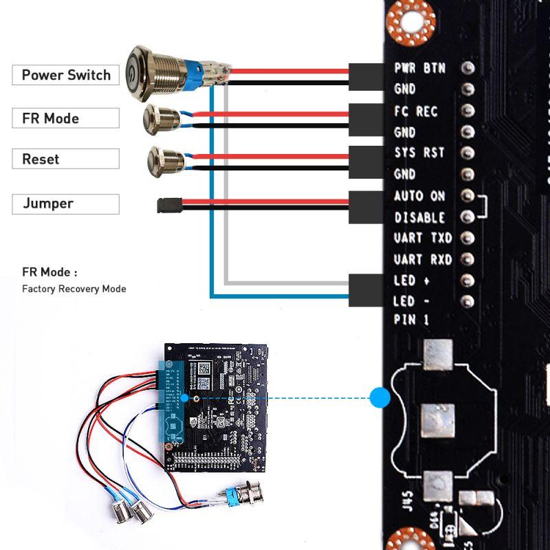
Let's now add our control buttons and status LED to the Jetson Nano. The pictures above show my setup and an alternative setup with a LED-button combination:
- Follow the images to attach the cables correctly.
- Ensure that ground is always connected to the correct pin for consistency. (this doesn't matter for the pushbuttons though).
Build Motor Controller
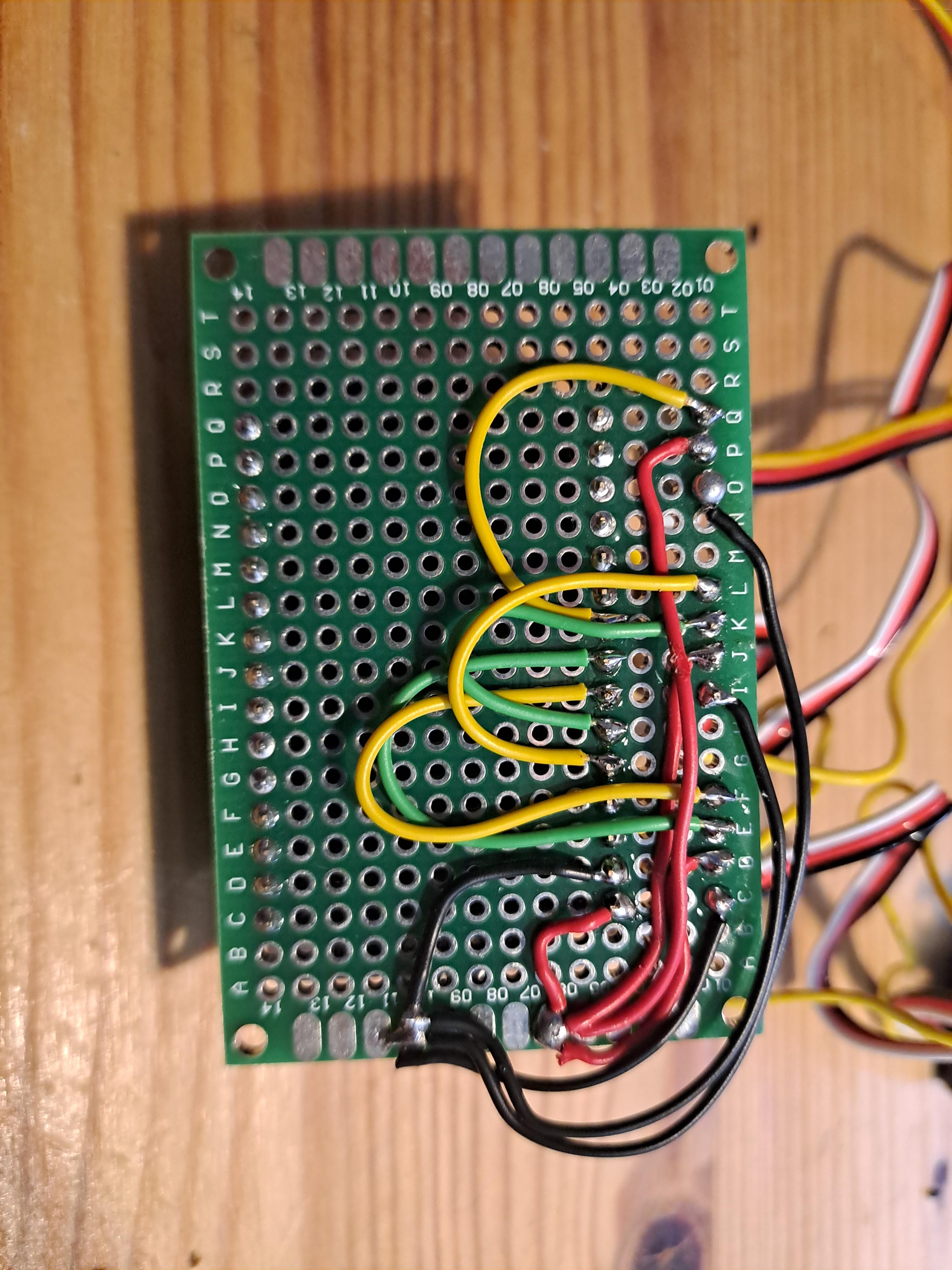
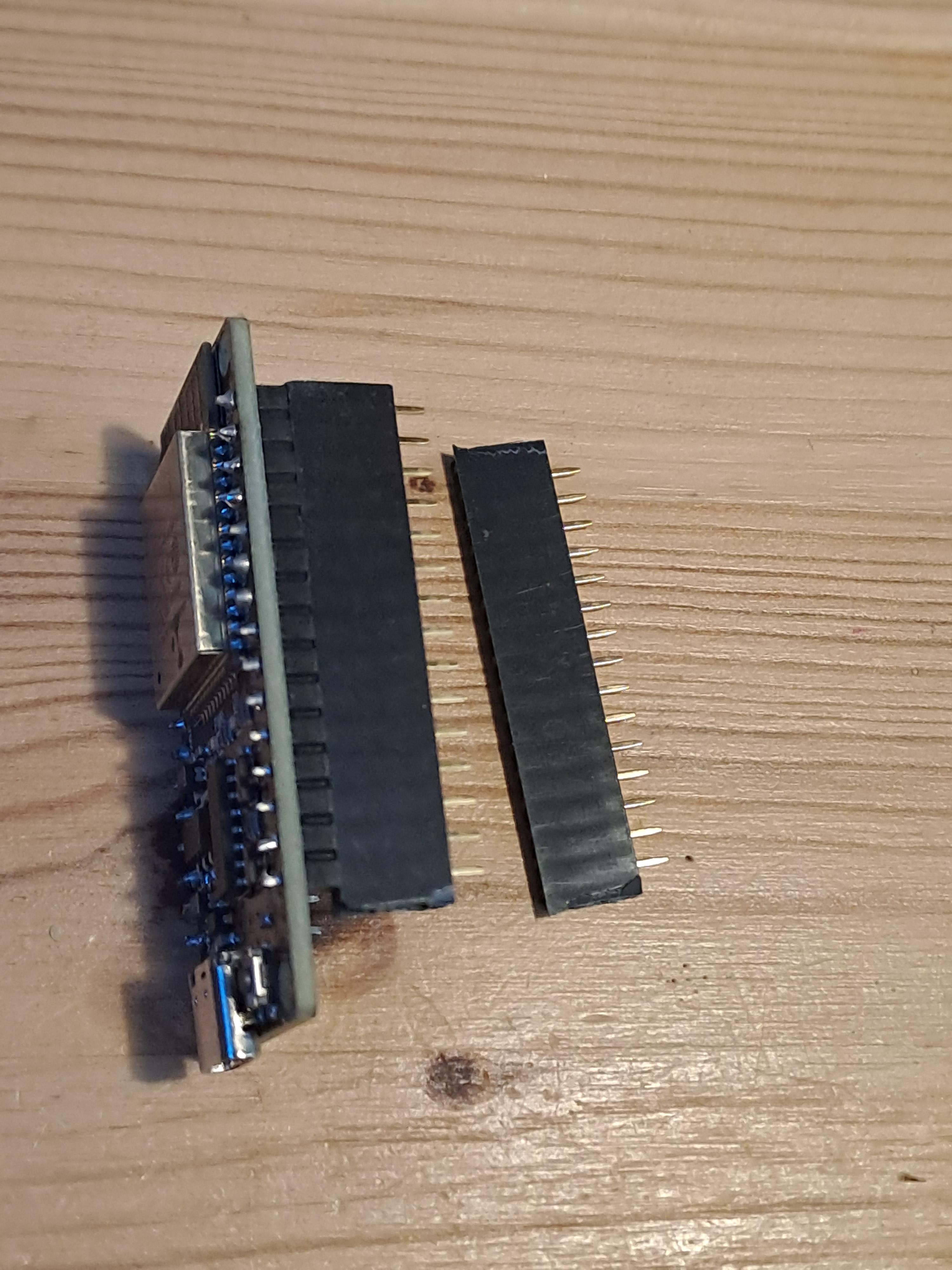
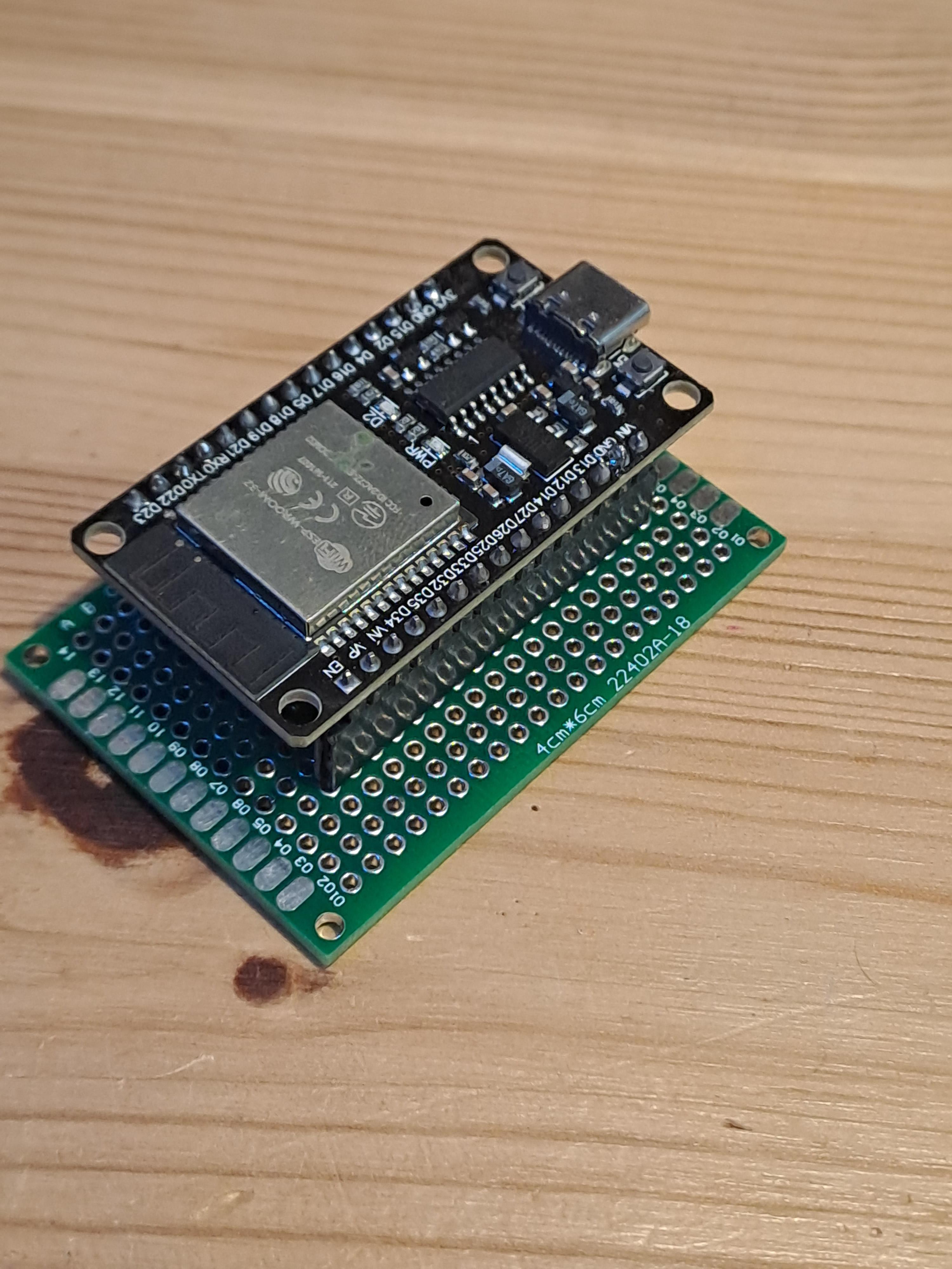
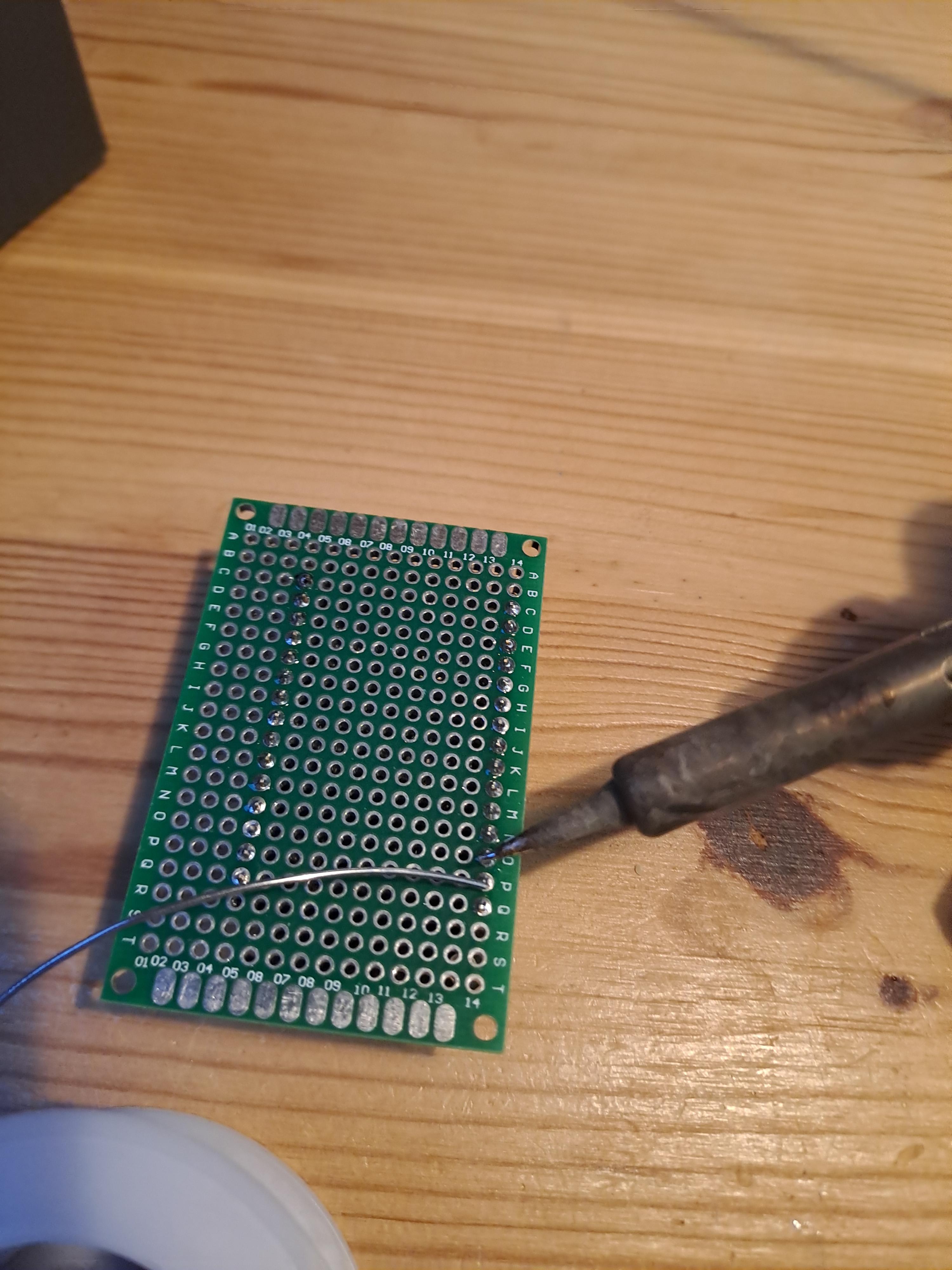
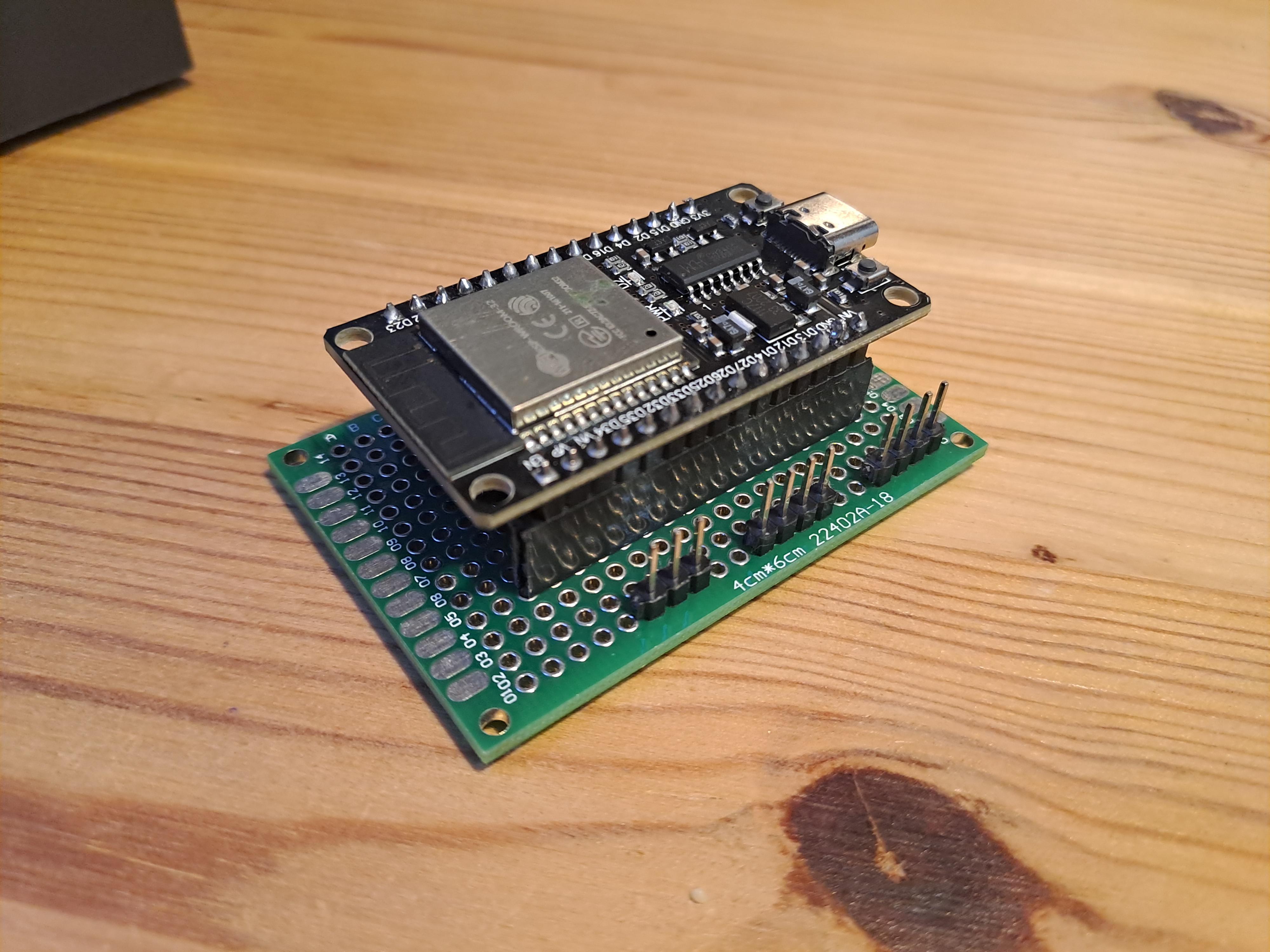
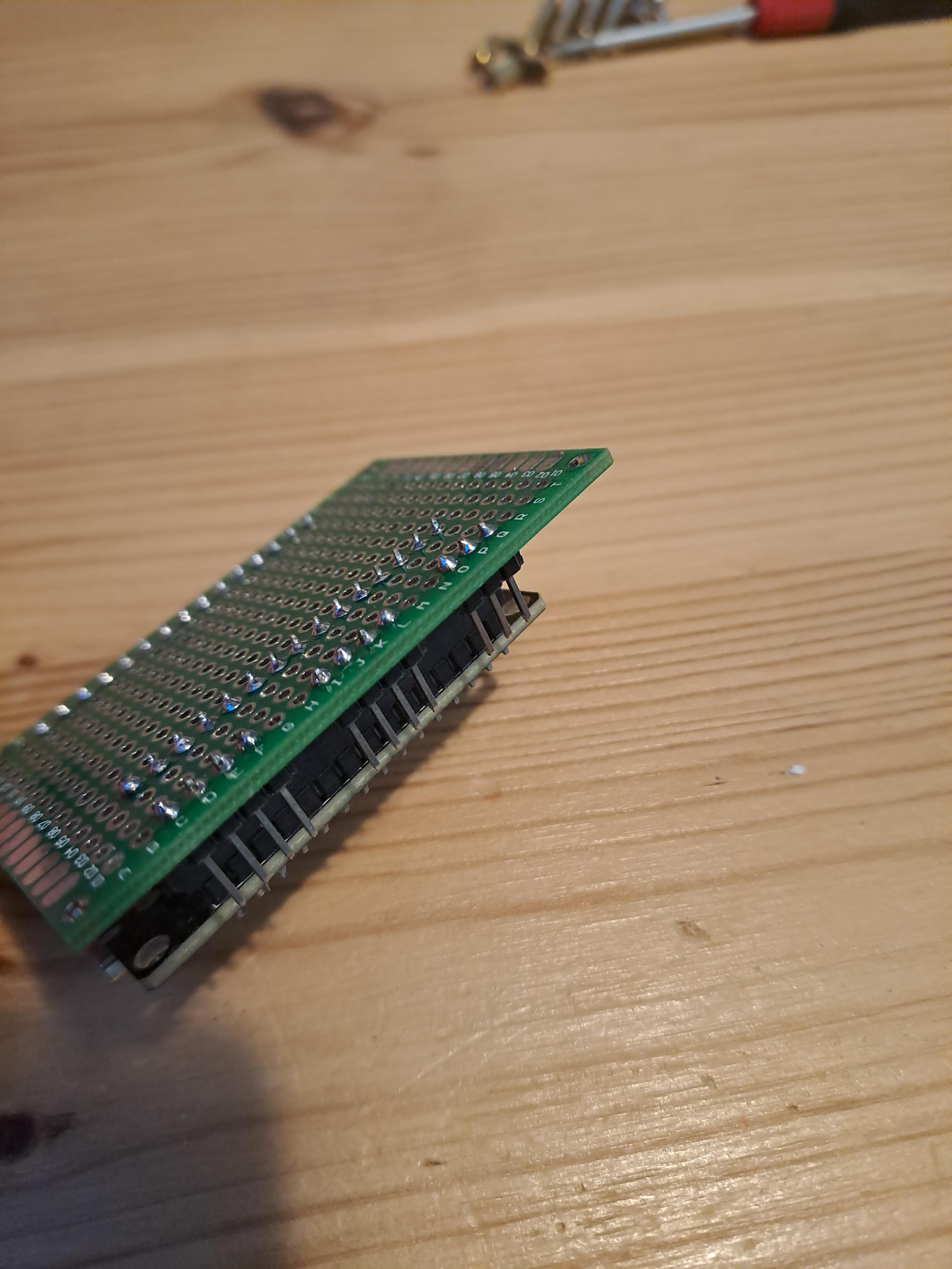
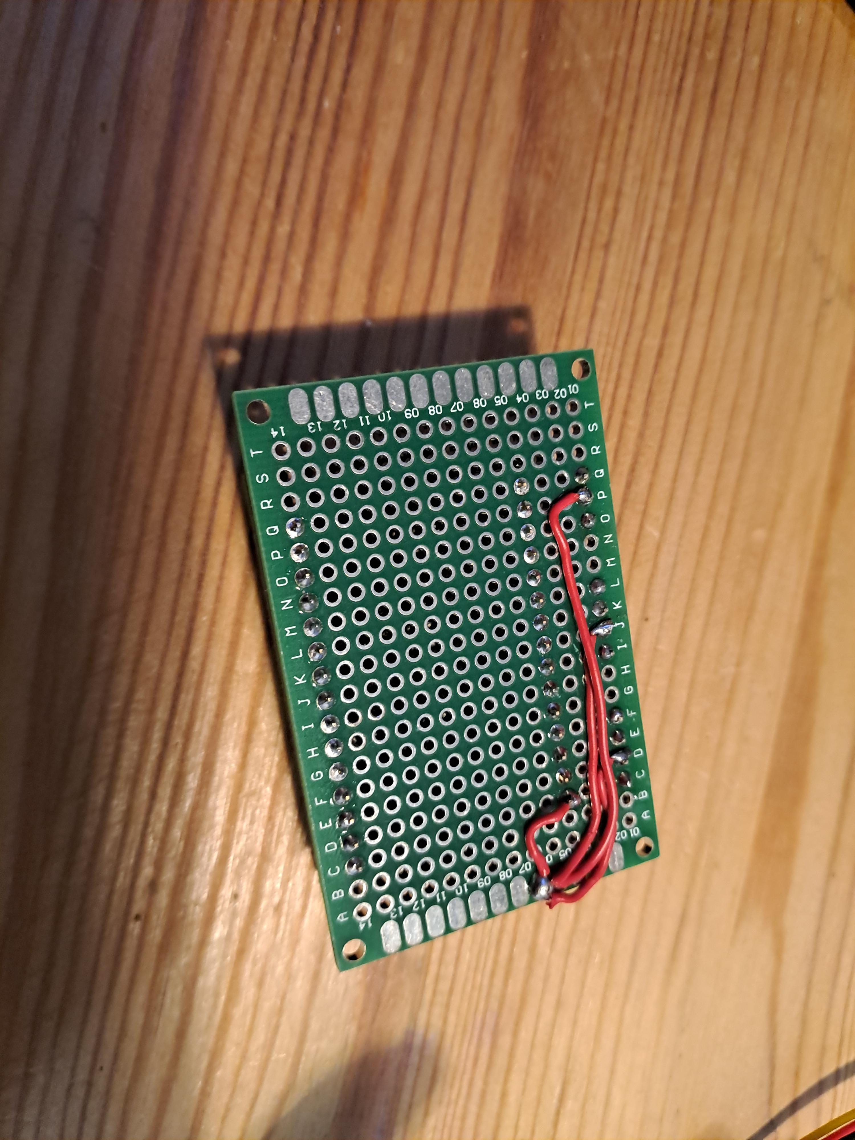
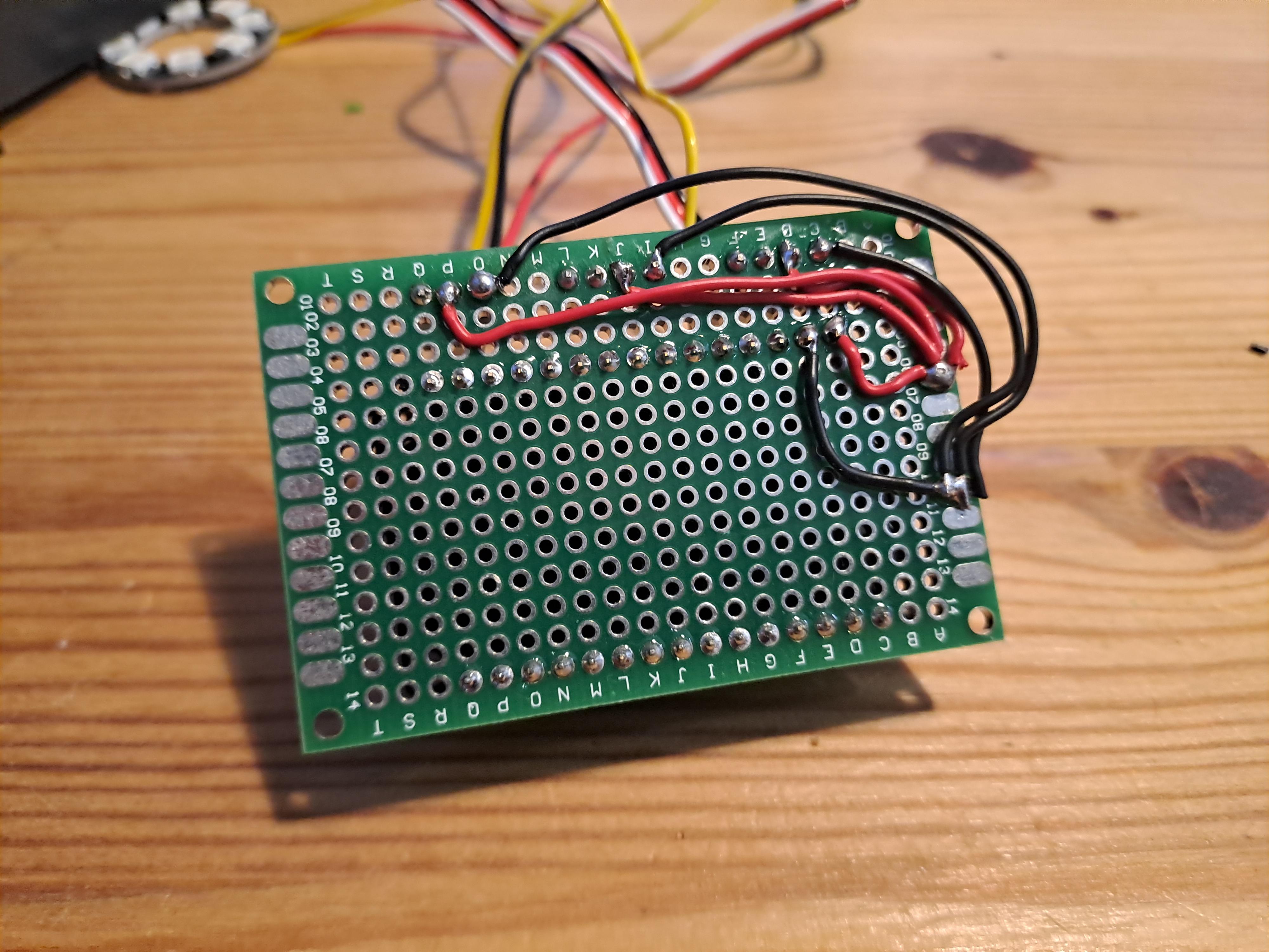
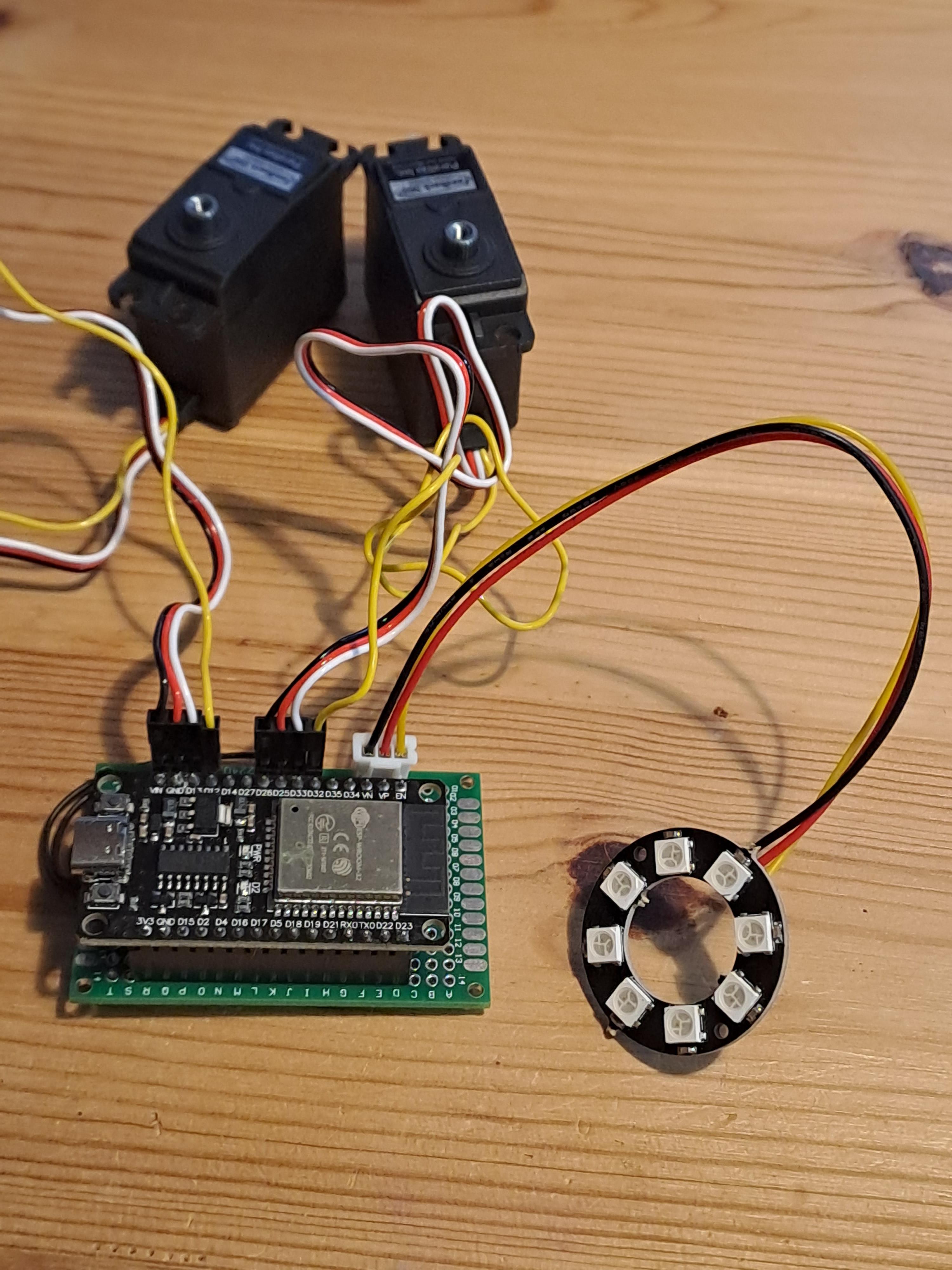
Now let's build the motor and status lights controller. You can also use an Arduino for this, or whatever micro-controller you have at hand. I use the ESP32 because I like it better than Arduino and it has some nicer feedback Servo libraries.
Please refer to the wiring diagram above to check how the servos and the Neopixel ring is connected.
In the wiring diagram the PWM cable is yellow (in my pictures it is white) and the sensor cable is blue (in my pictures it is yellow).
You have two options here: connect the cables directly to the pins of the micro-controller or use a perf board like I did. I might make a PCB board for this some day, check the github projects for updates.
As an additional advice: I use a cheap NanoPixel board here (it did cost less than 2EUR). After a few days, some of the NeoPixels stopped working properly. I recommend you invest a bit more to buy a more decent board if you want a nice looking result.
Upload Code to ESP32
Now let's upload the code to the ESP32 board:
- Download the code from the github project.
- Download and install the Arduino IDE.
- If you have never used the Arduino IDE with ESP32 devices, have a look at this tutorial first.
- Open the downloaded code in the Arduino IDE
- You will need to install two libraries: Adafruit_NeoPixel.h and ESP32Servo360.h
- Select the COM port of your ESP32 device
- Upload the code to your ESP32
- Once powered, the status NeoPixel ring should light up immediately and the servos will move to 15 degrees (the default position).
Horizontal Feedback Servo
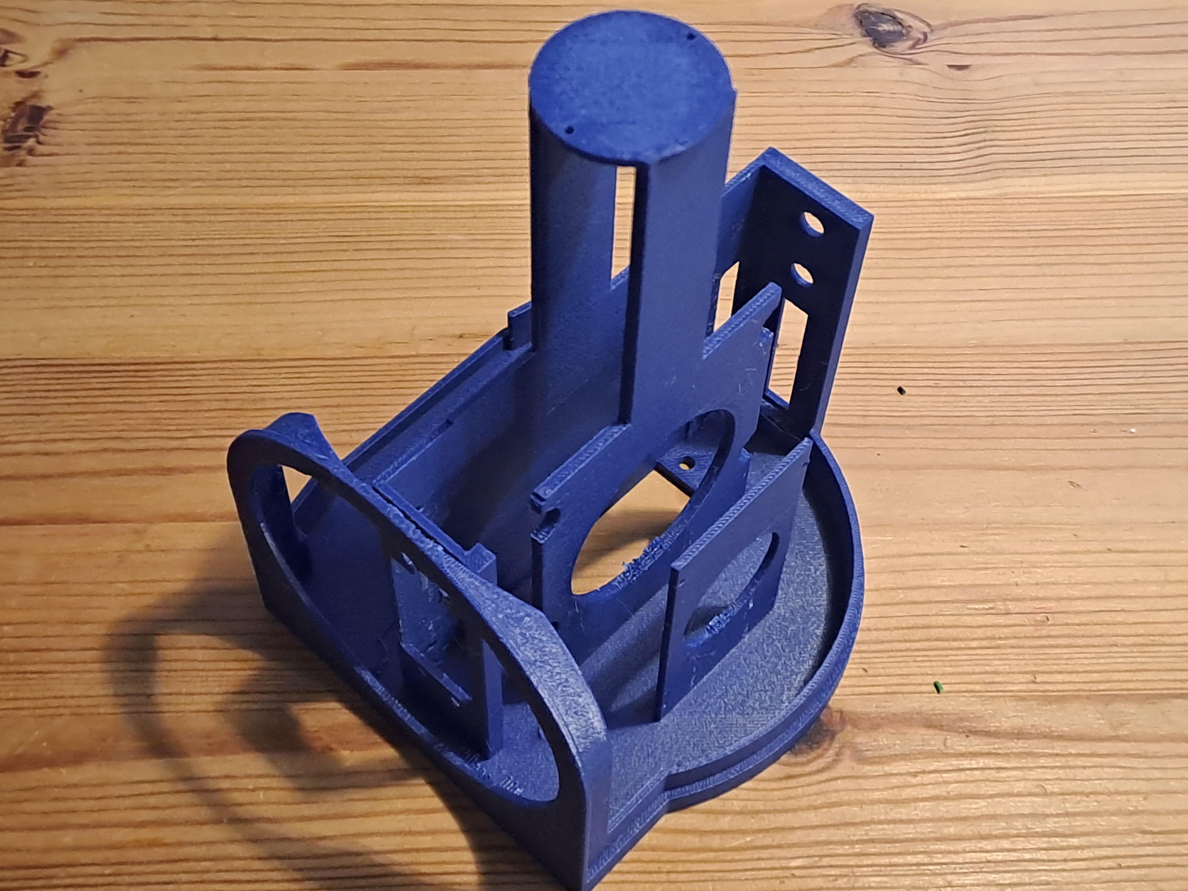
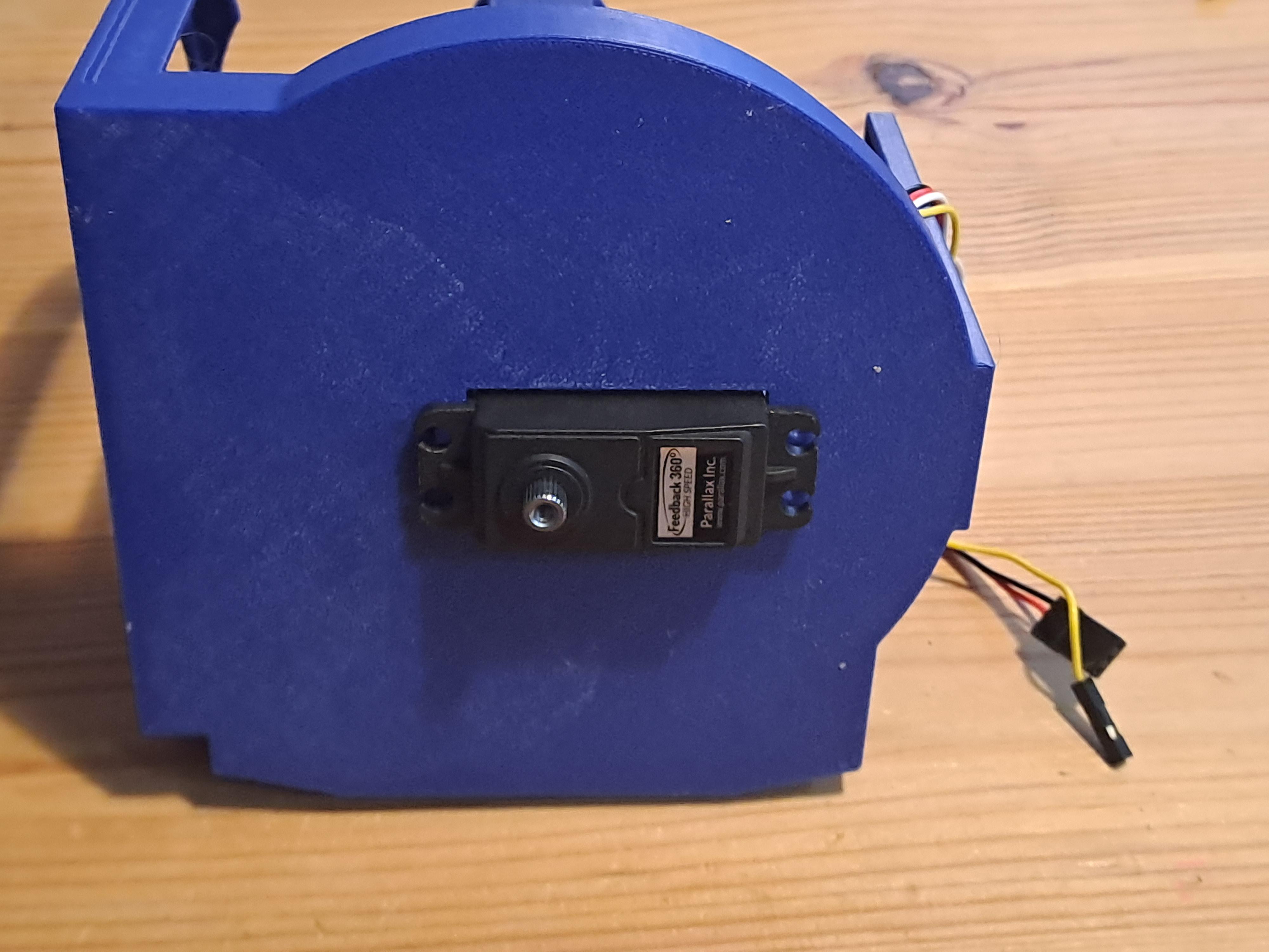
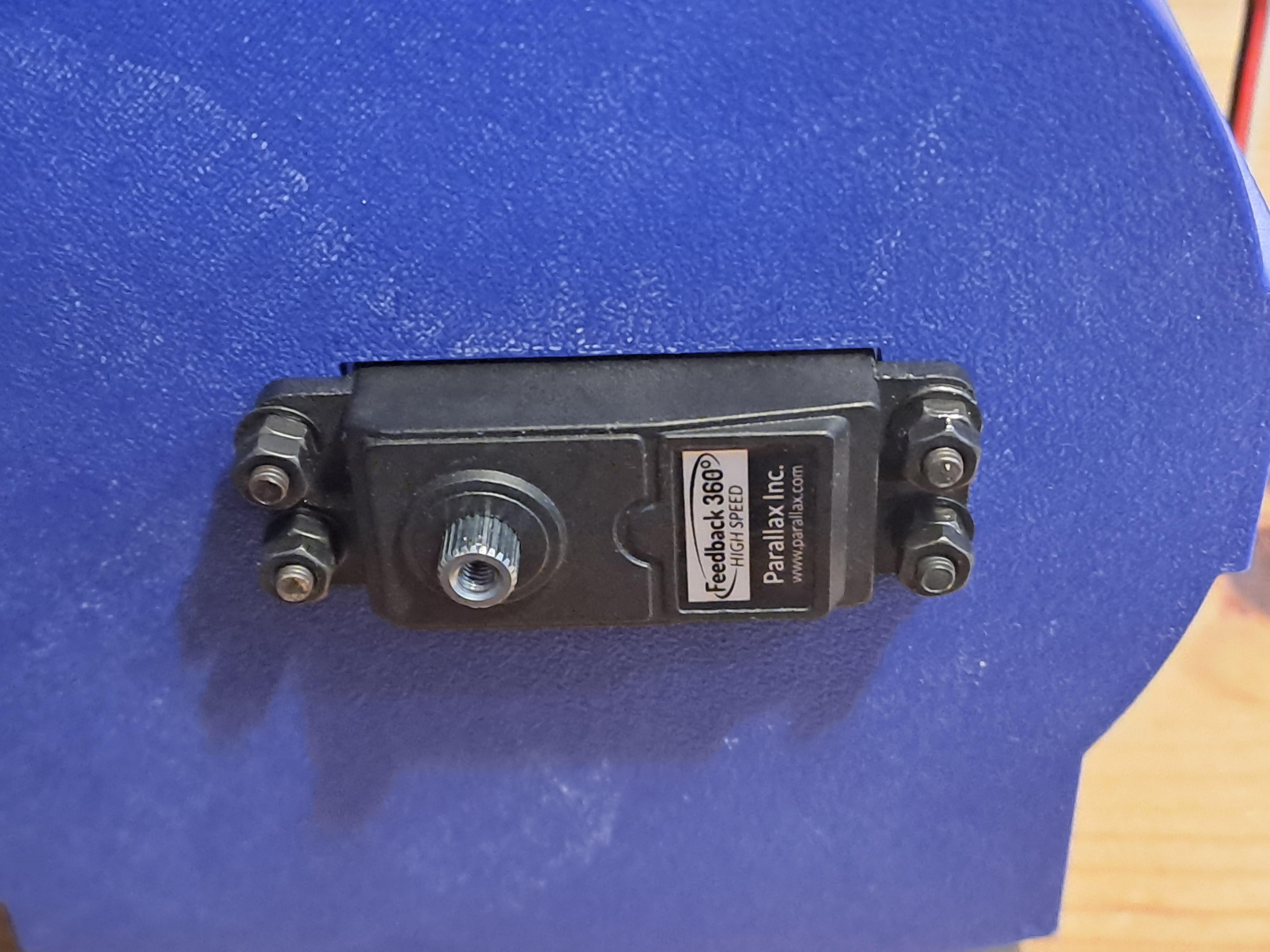
Let's now install the Horizontal Feedback Servo:
- Mount the horizontal feedback servo on the main base plate.
- Ensure the servo axis is centered. Use screws and washers to secure it.
- Route the servo cable neatly through the 3D print.
Add Base Disk
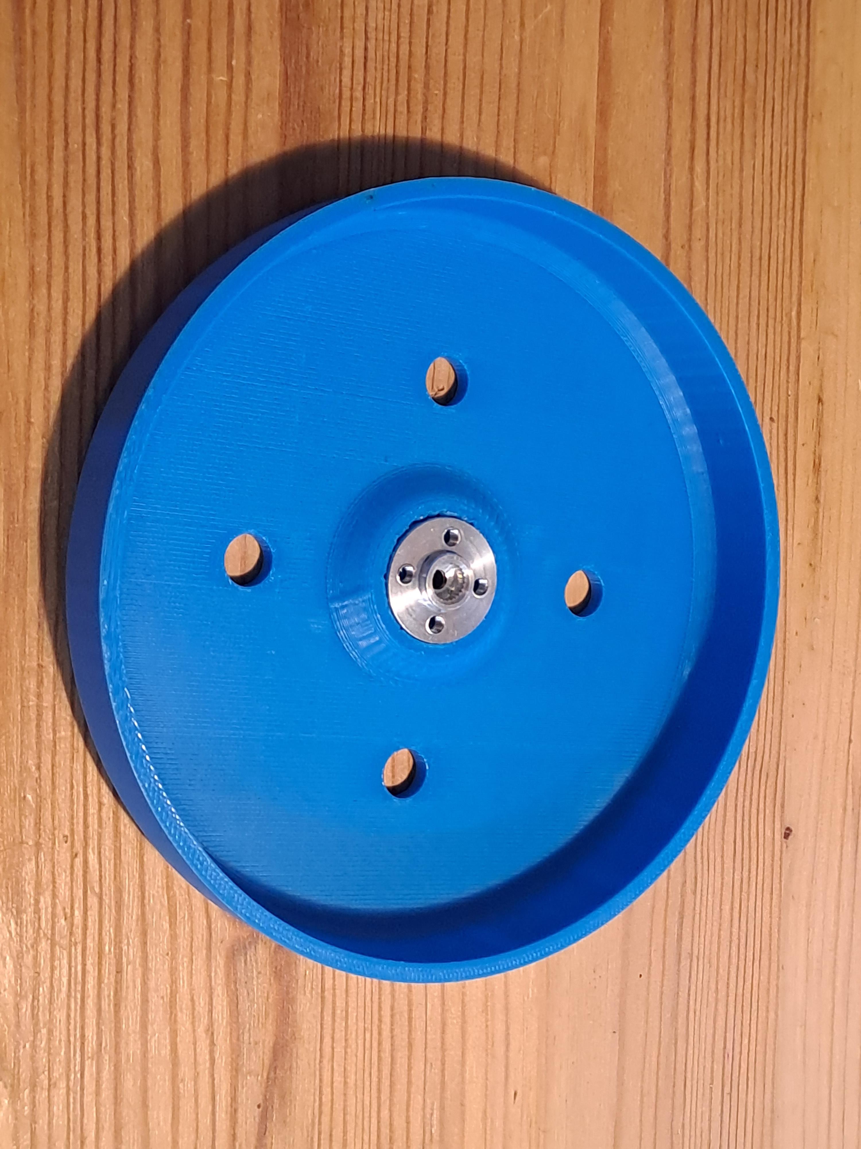
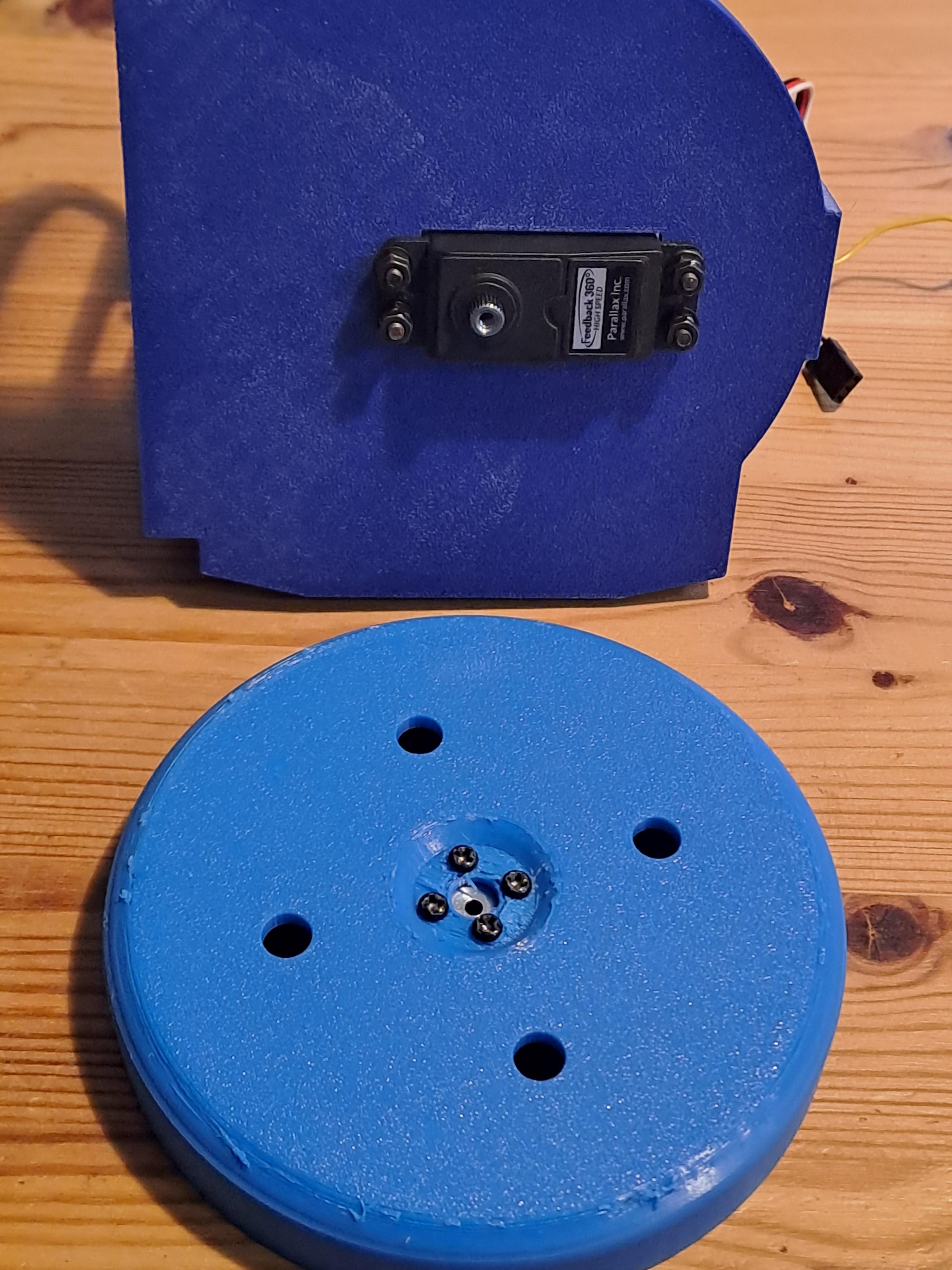
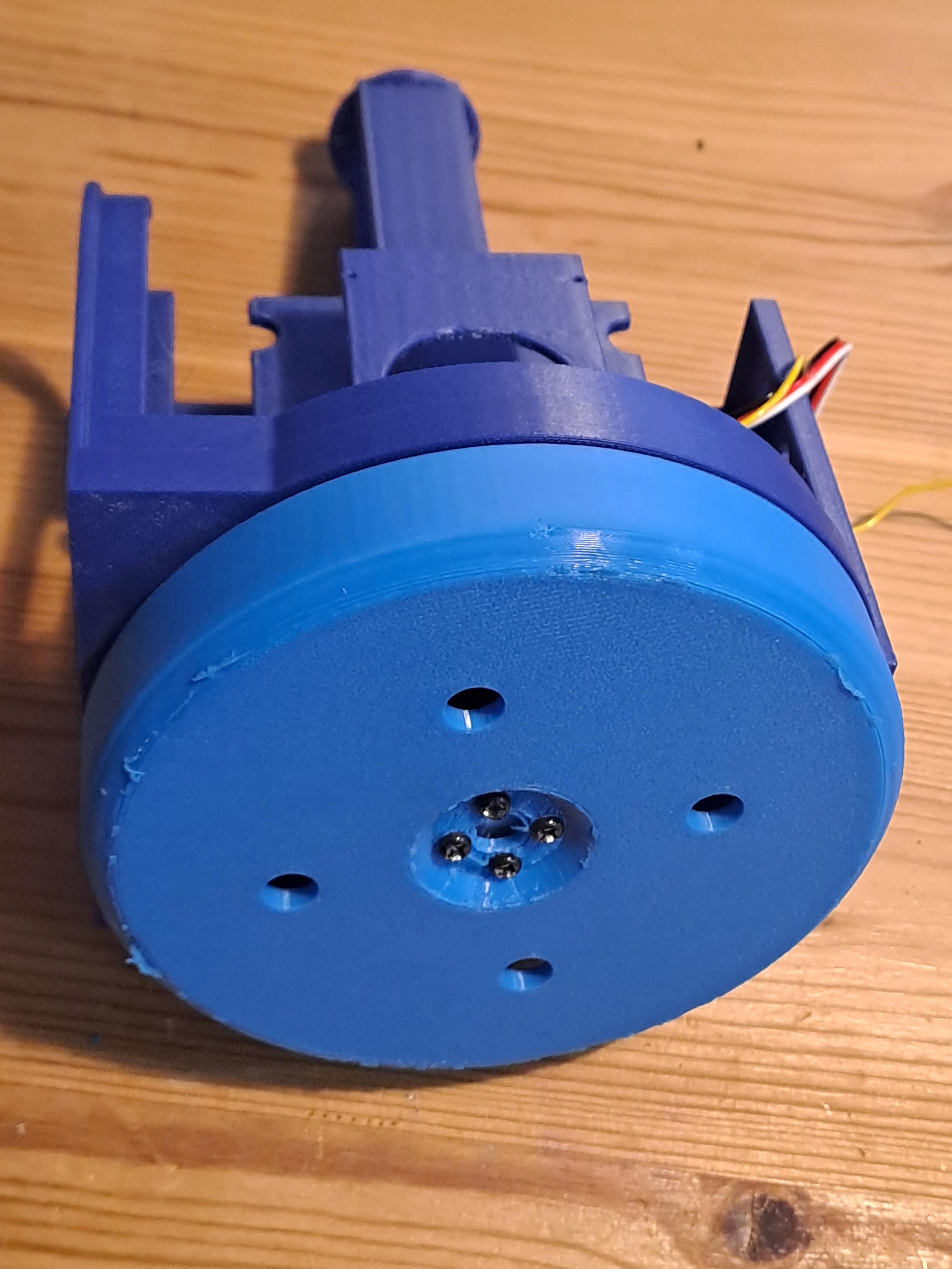
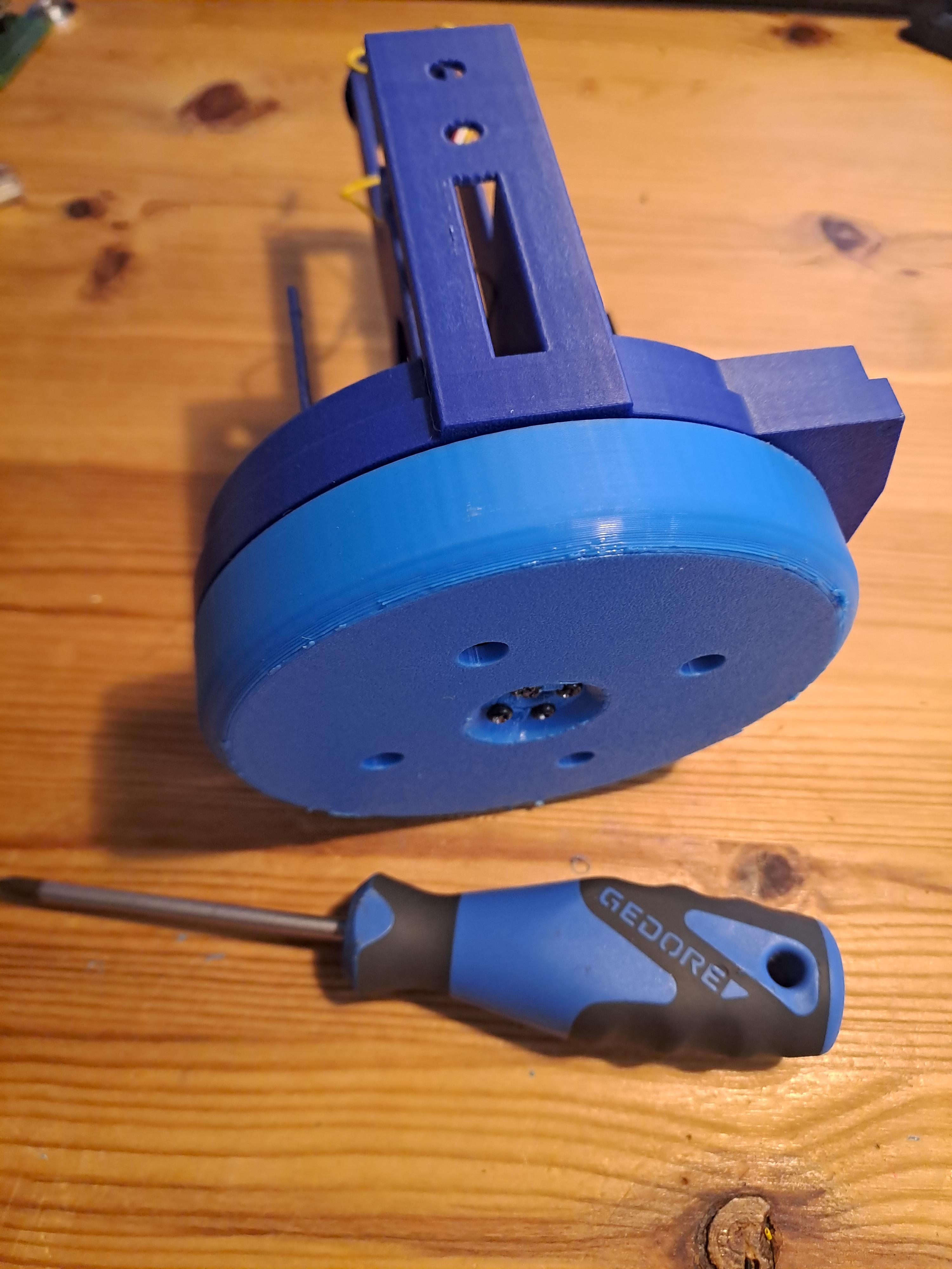
Let's now add the base disk. You might have to remove it later again to mount it on a post or a camera tripod. However, attaching it now helps during the building process:
- Attach the fancy aluminum servo disk to the base disk using four screws.
- Secure the base disk to the servo and test for smooth 360° movement. The disk should move easily without touching the main body of the camera platform.
Add Vertical Feedback Servo
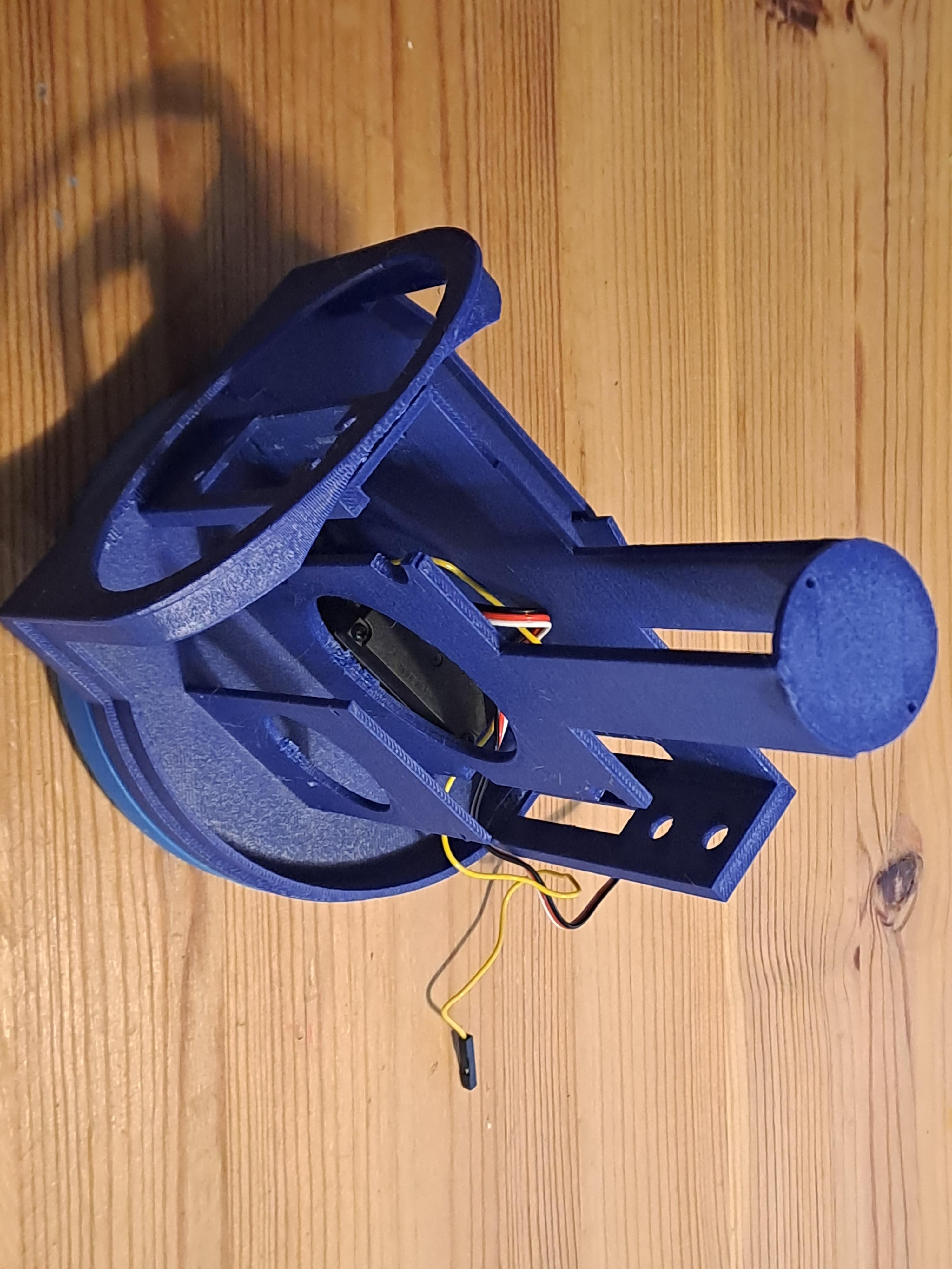
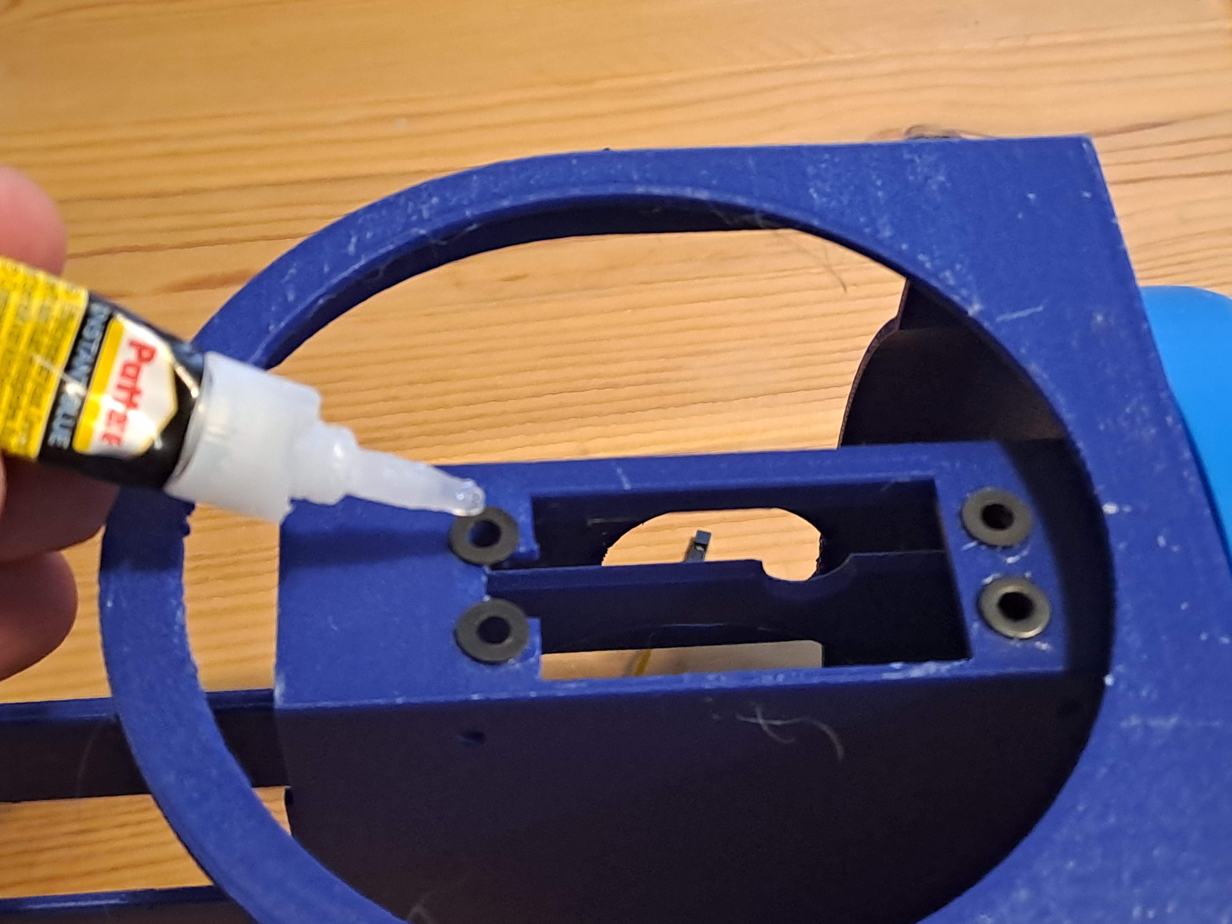
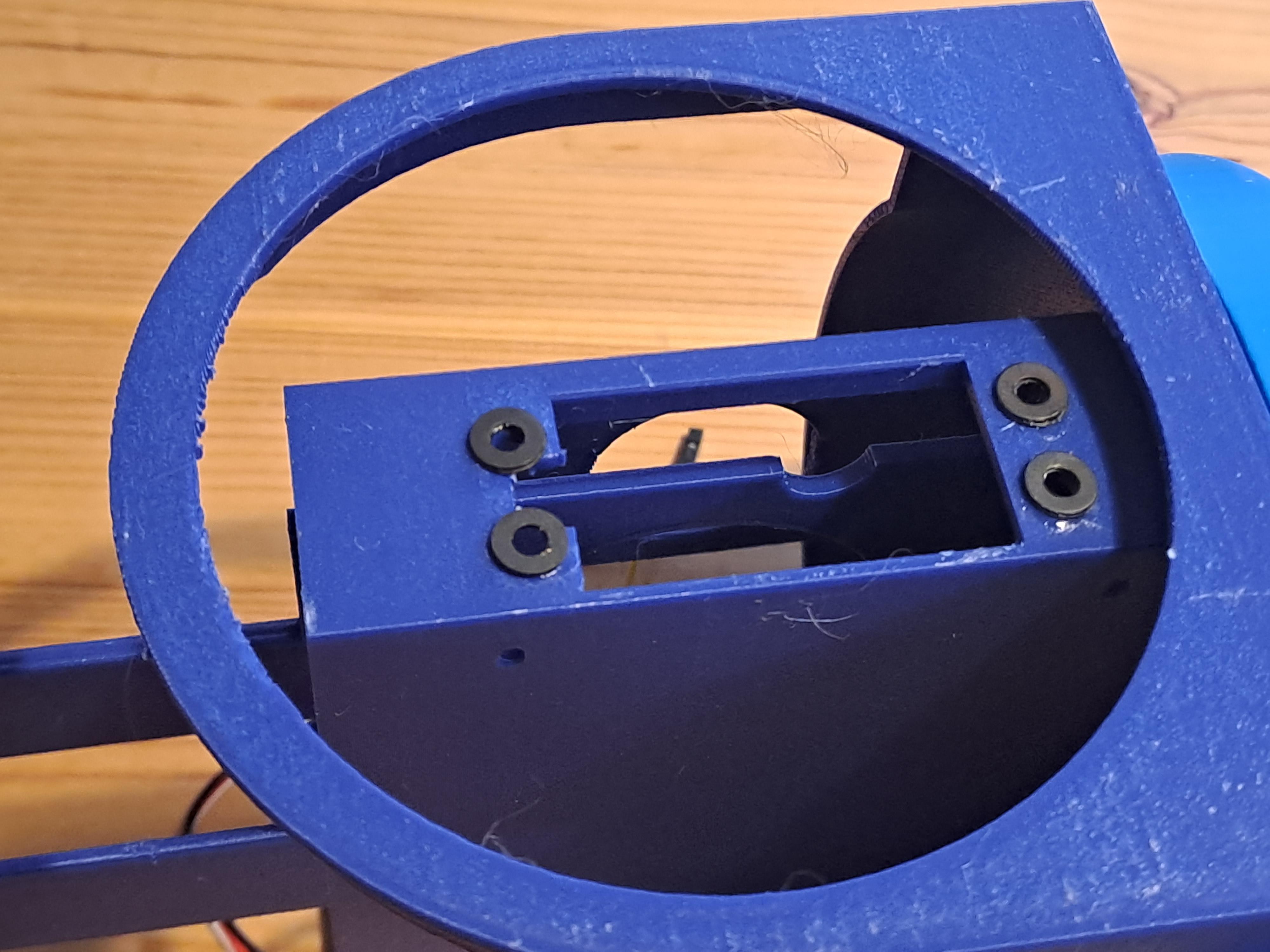
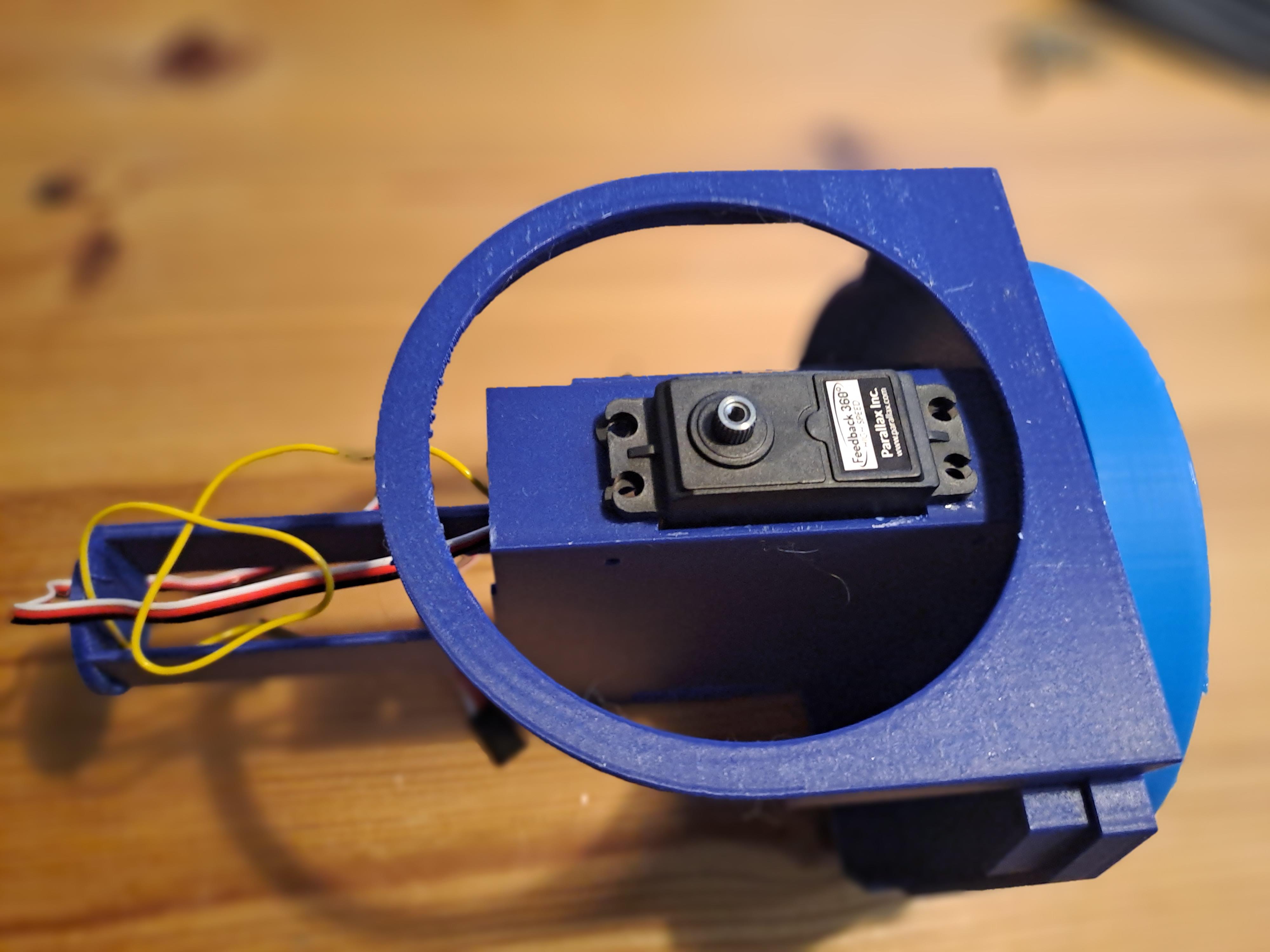
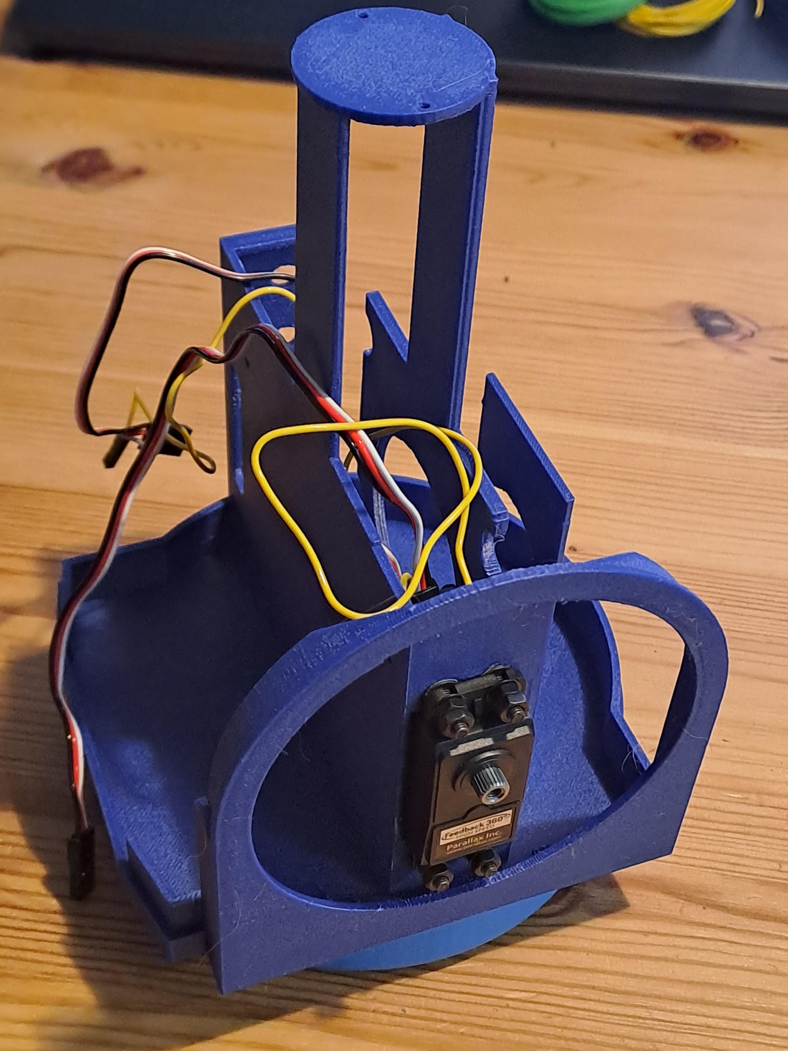
Now we can add the Vertical Feedback Servo:
- Position the vertical feedback servo on the vertical camera wheel’s axis.
- If your 3D printer is imprecise, add washers or spacers to create clearance between the servo and main body. As you can see I use super glue to keep the washers in place before attaching the screws.
- Secure the servo, ensuring cables are not squeezed or tangled.
Install Indicator NeoPixel Ring
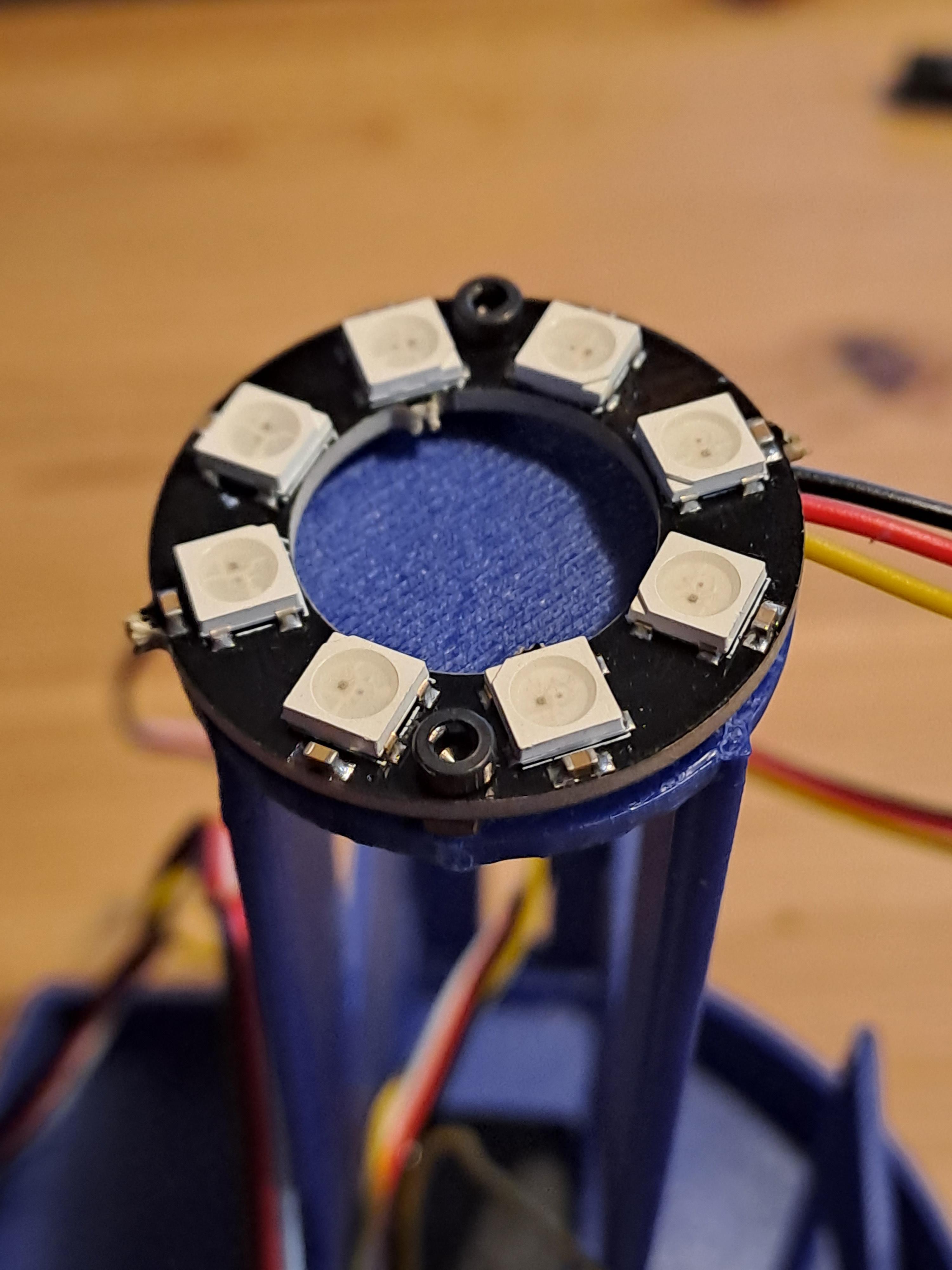
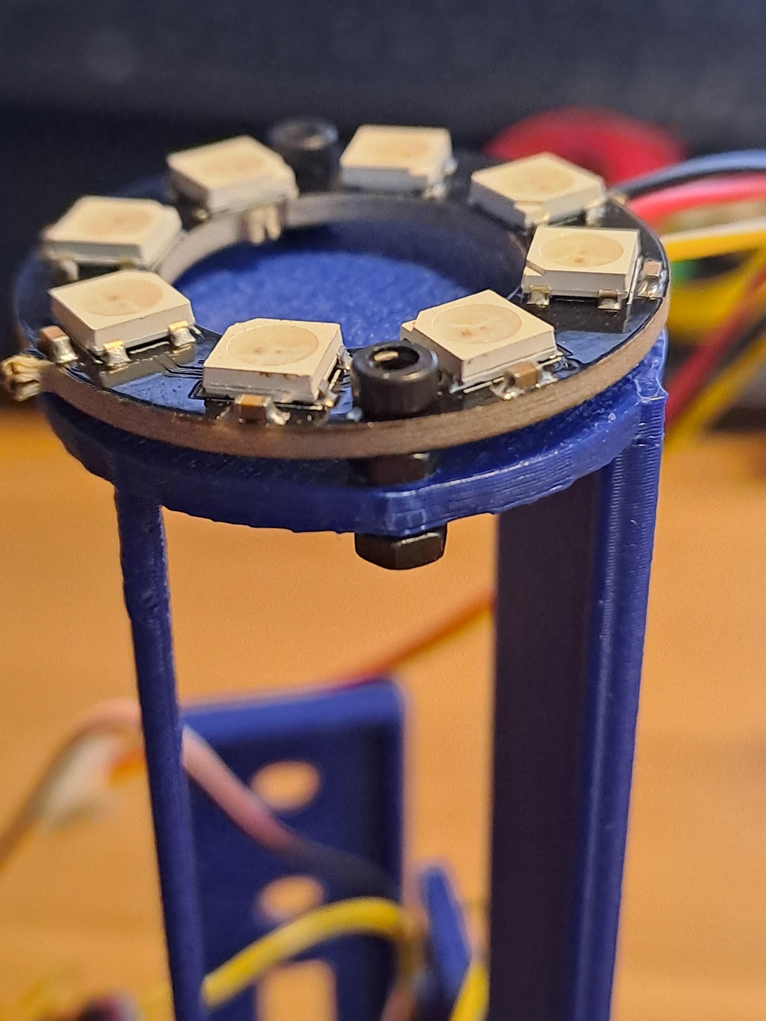
- Screw the Neopixel ring into the 3D-printed tower or secure it with hot glue.
- Route cables carefully to avoid interference.
Install Servo Controller and Connect
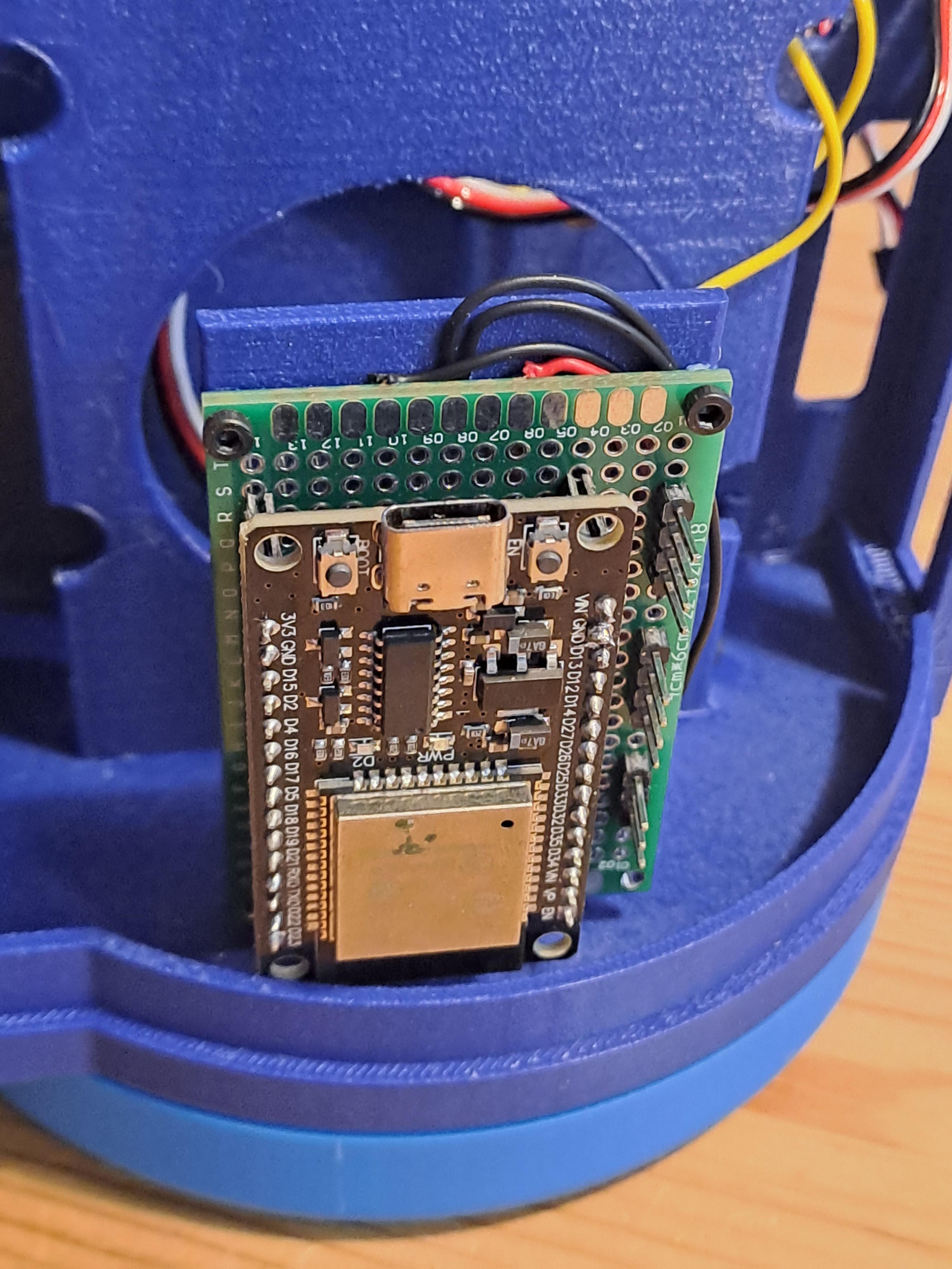
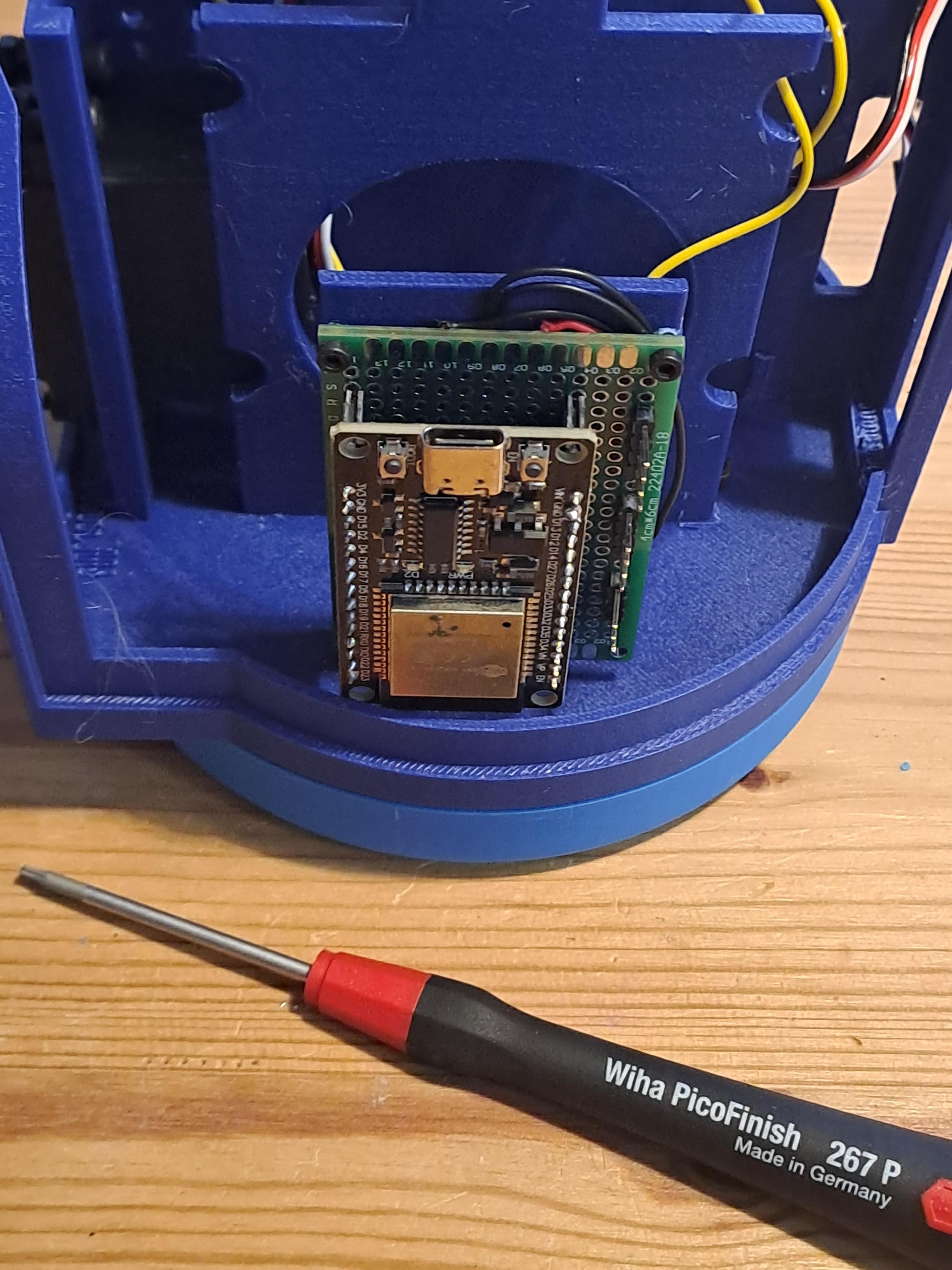
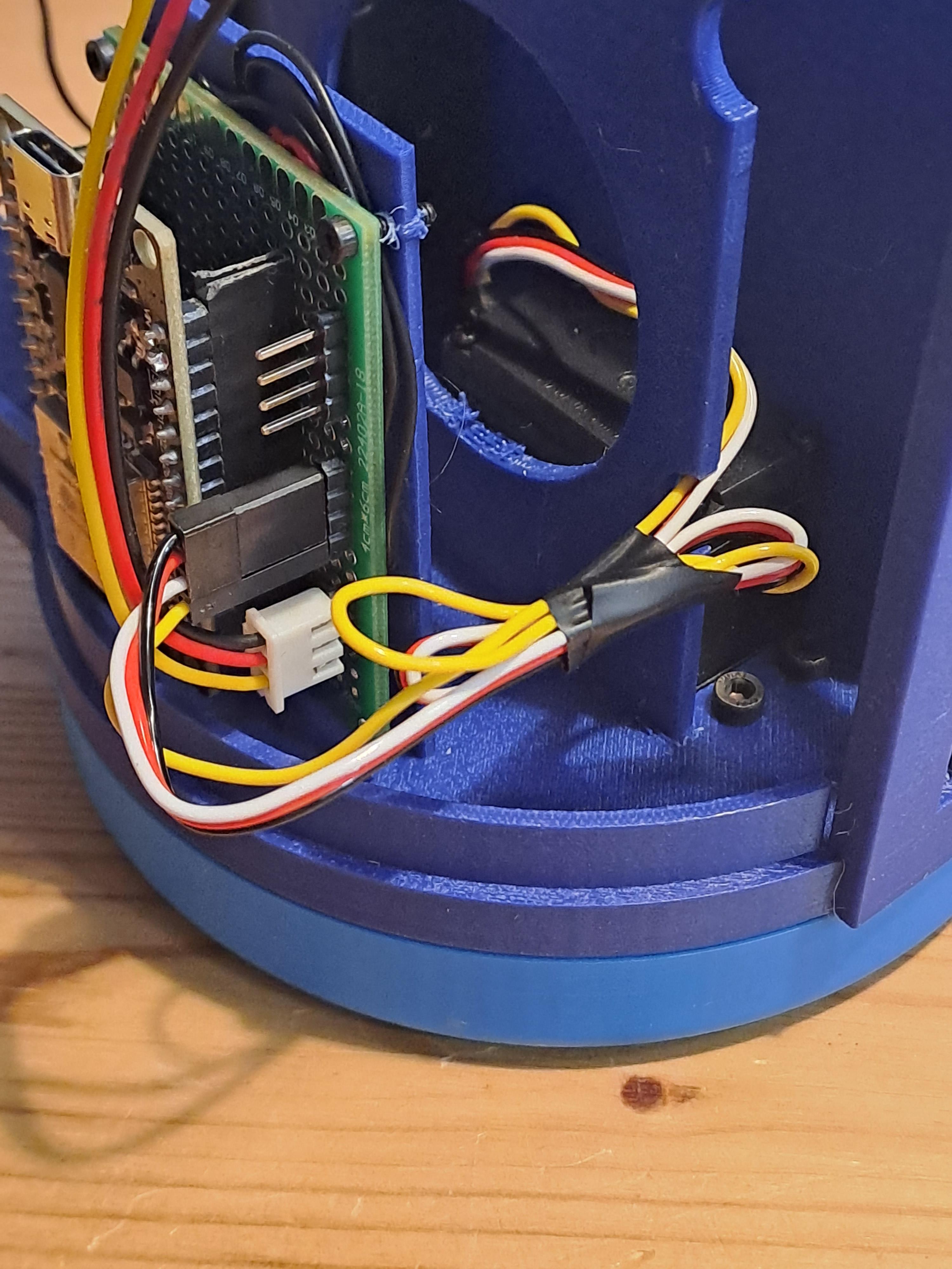
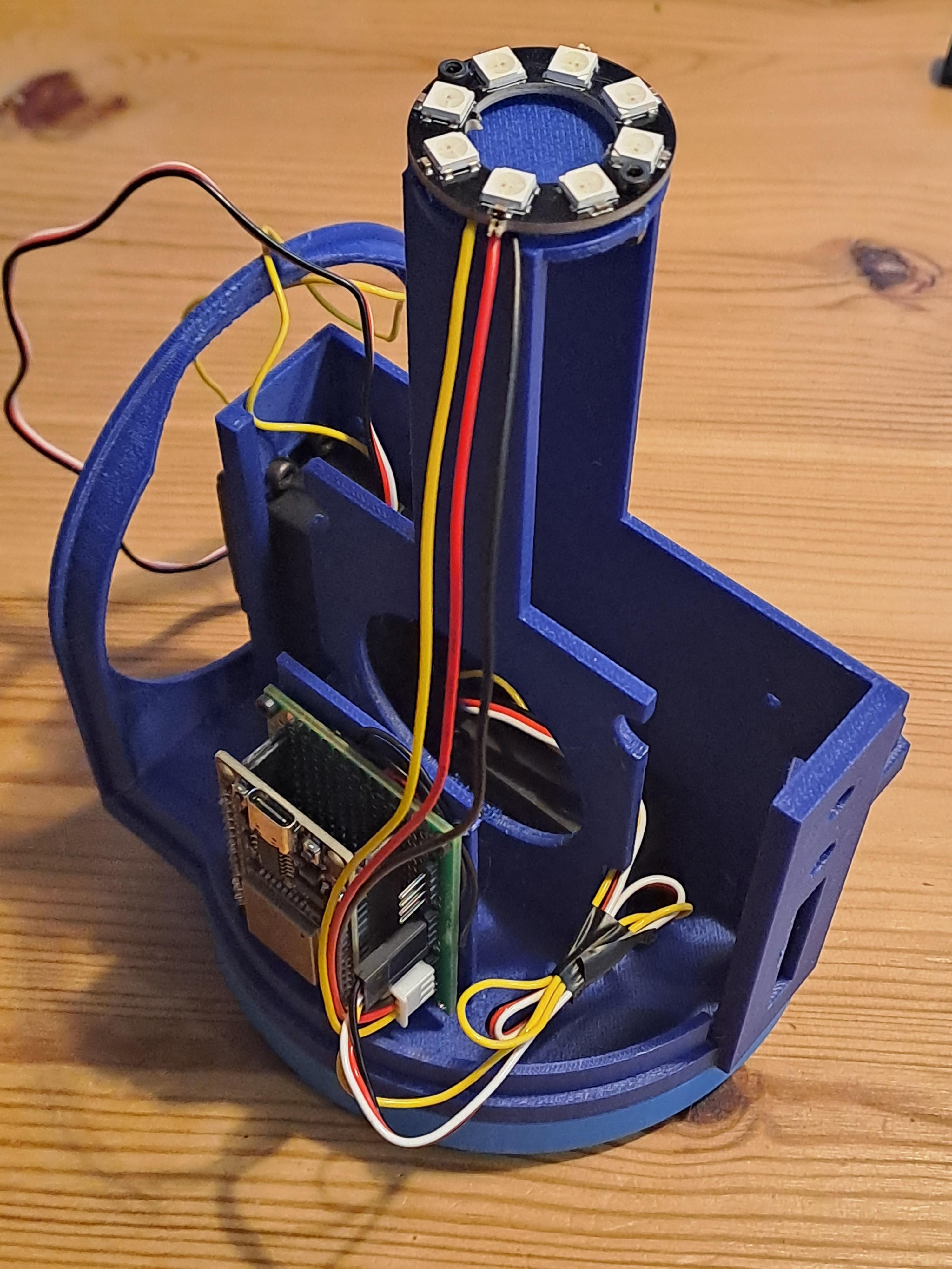
- Attach the servo controller board to the main assembly using screws or hot glue.
- Manage cables using zip ties to ensure they don’t interfere with the rotating parts.
Install WiFi Antenna Sockets
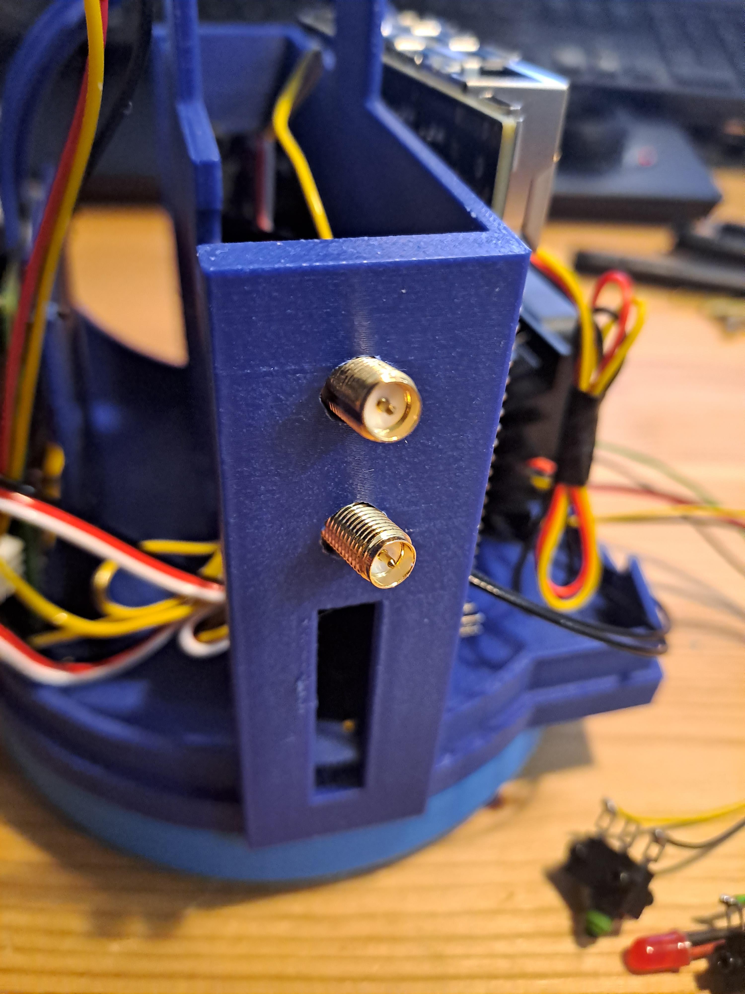
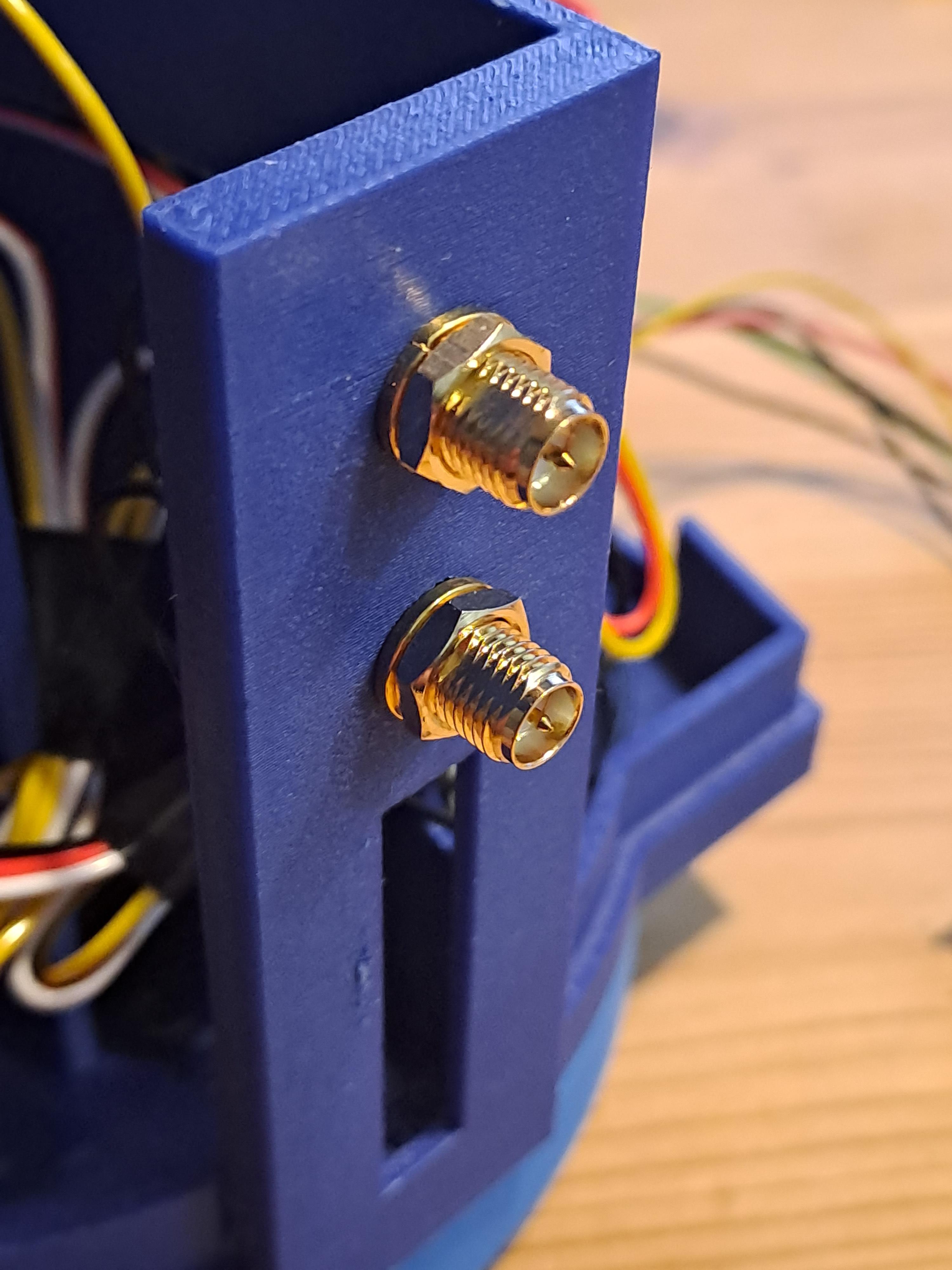
Insert the WiFi antenna sockets into the upper holes and secure with a washer and nut.
Add Switches and LED
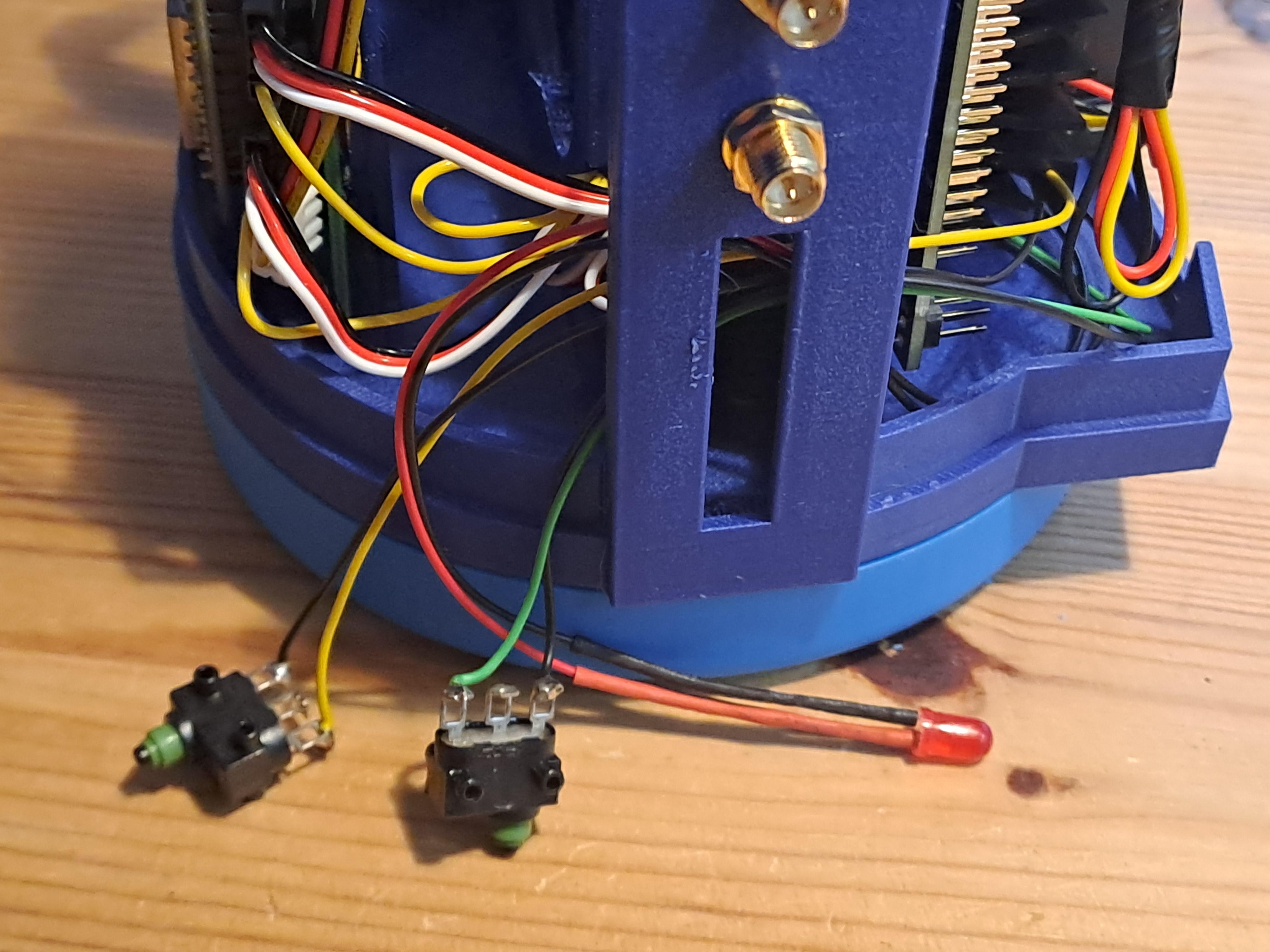
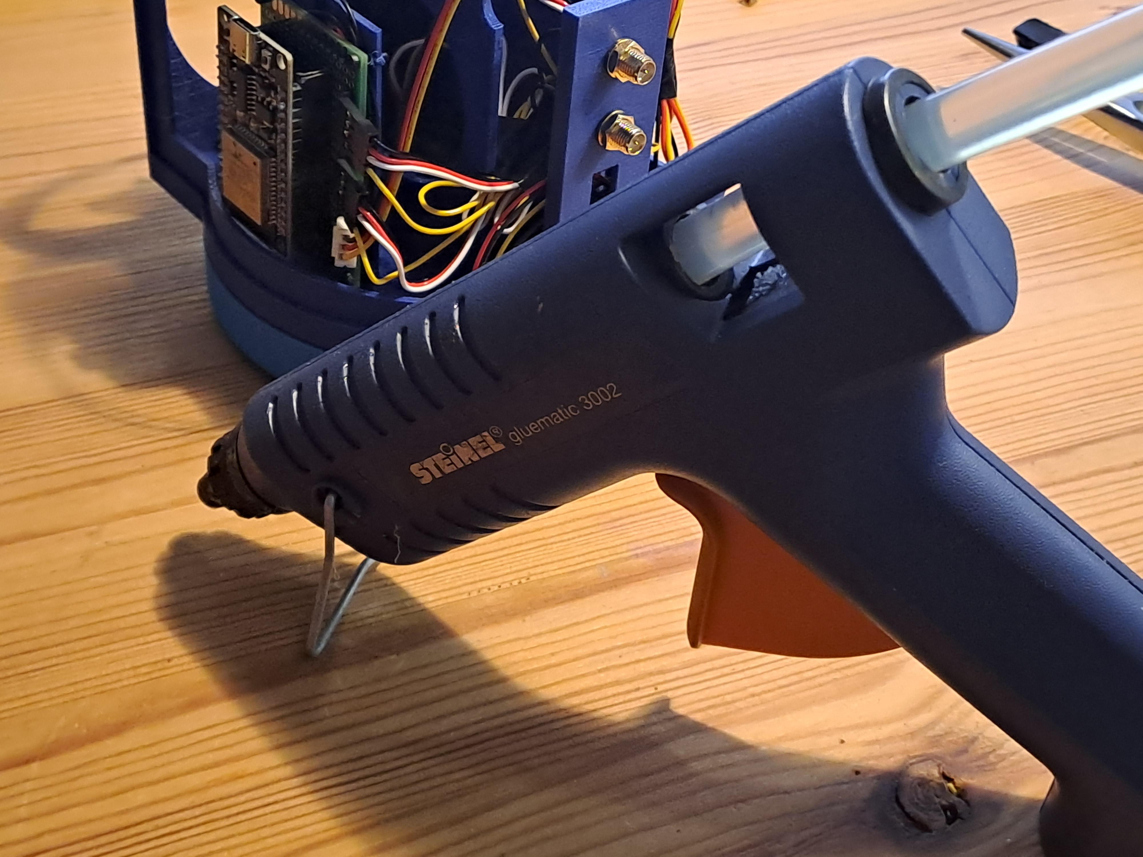
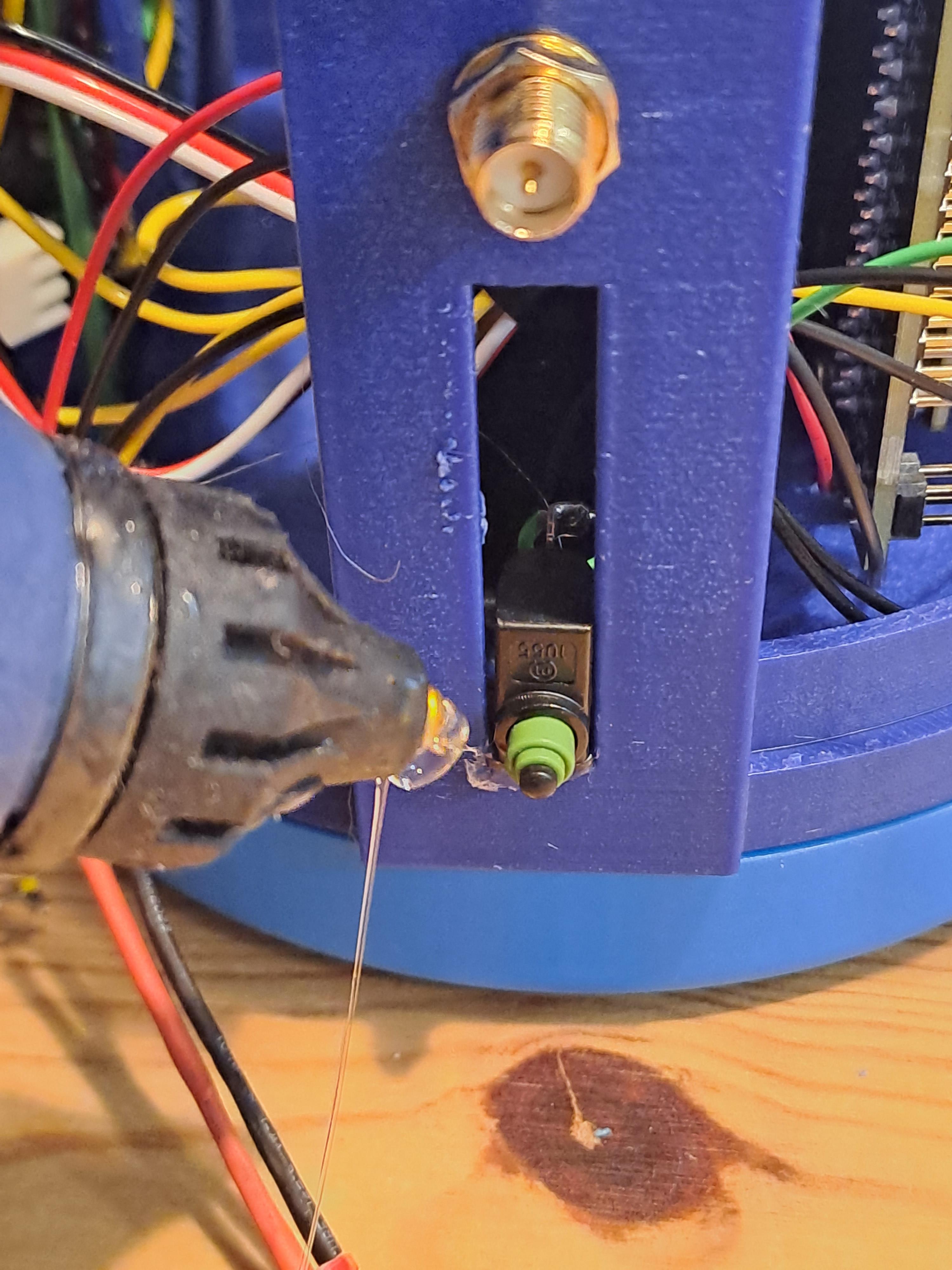
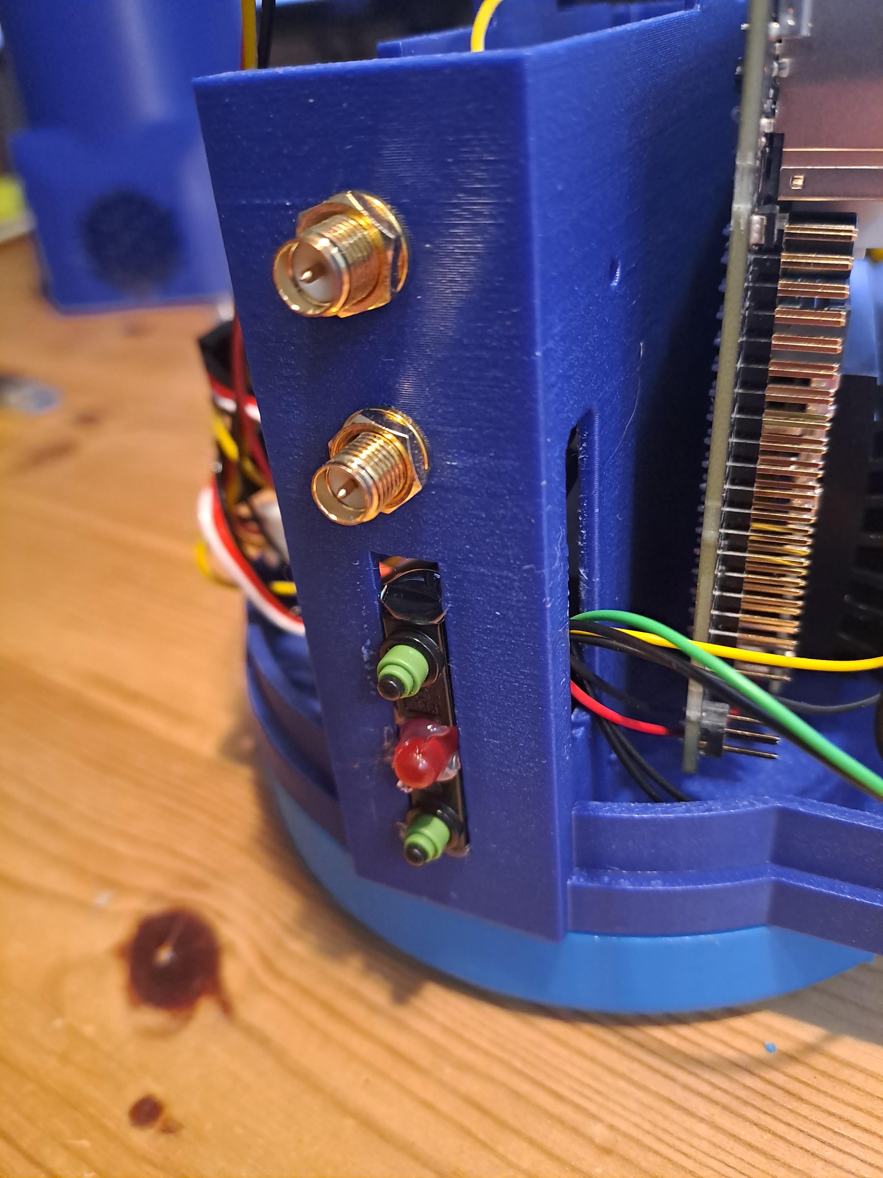
- Position the switches and LED in the designated holes.
- Secure them with hot glue or appropriate mounts.
- Use images as a reference.
Prepare Camera Wheel
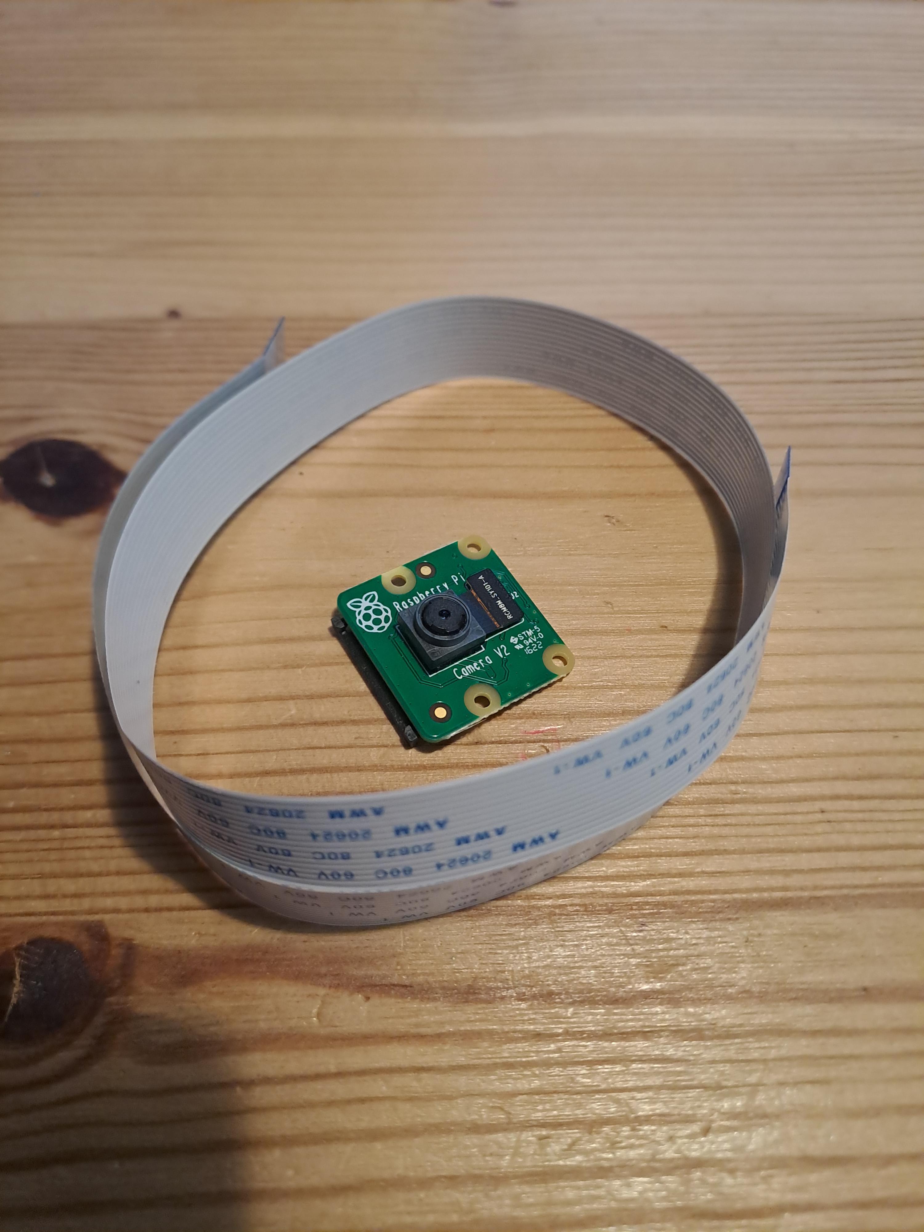
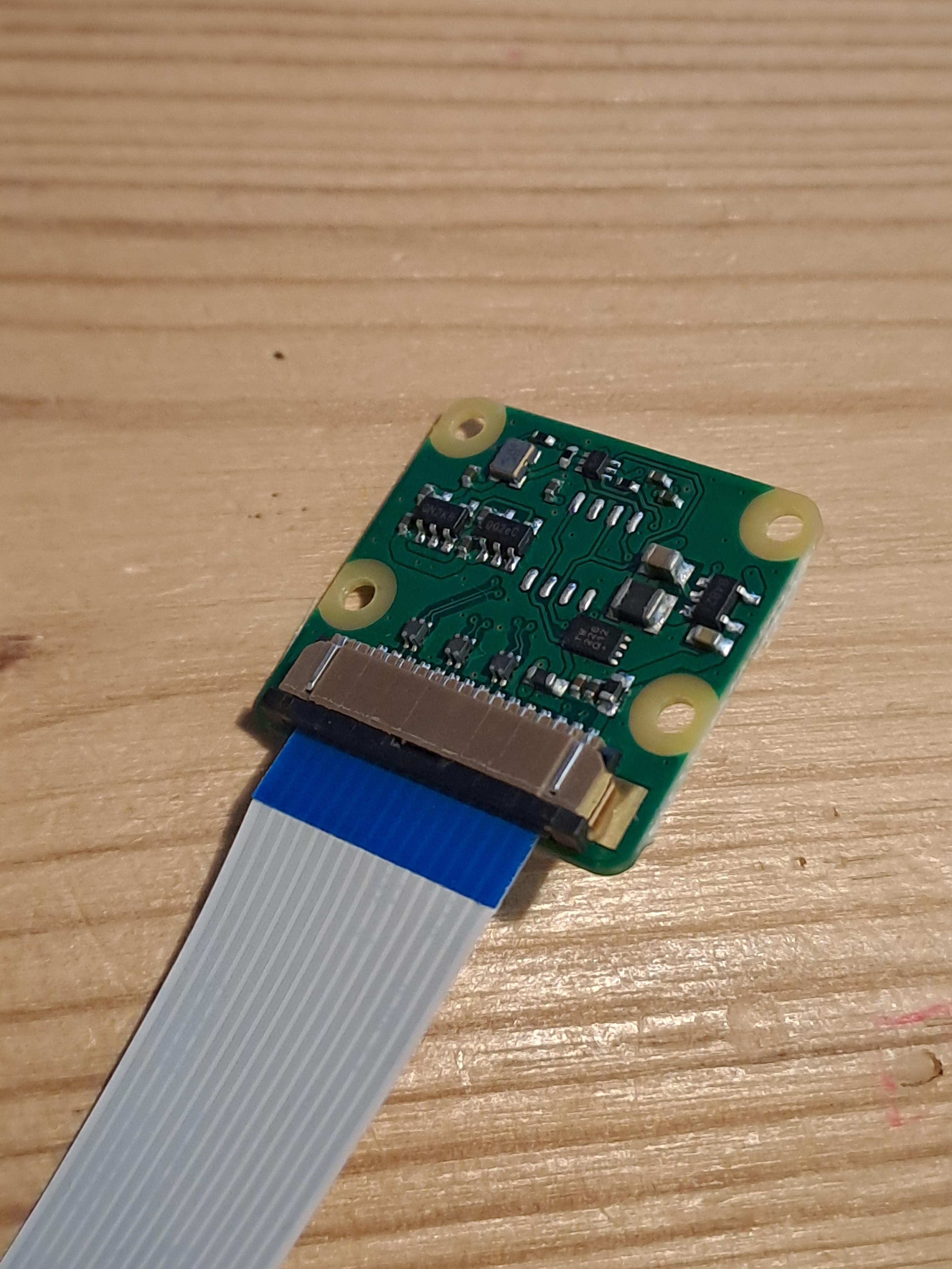
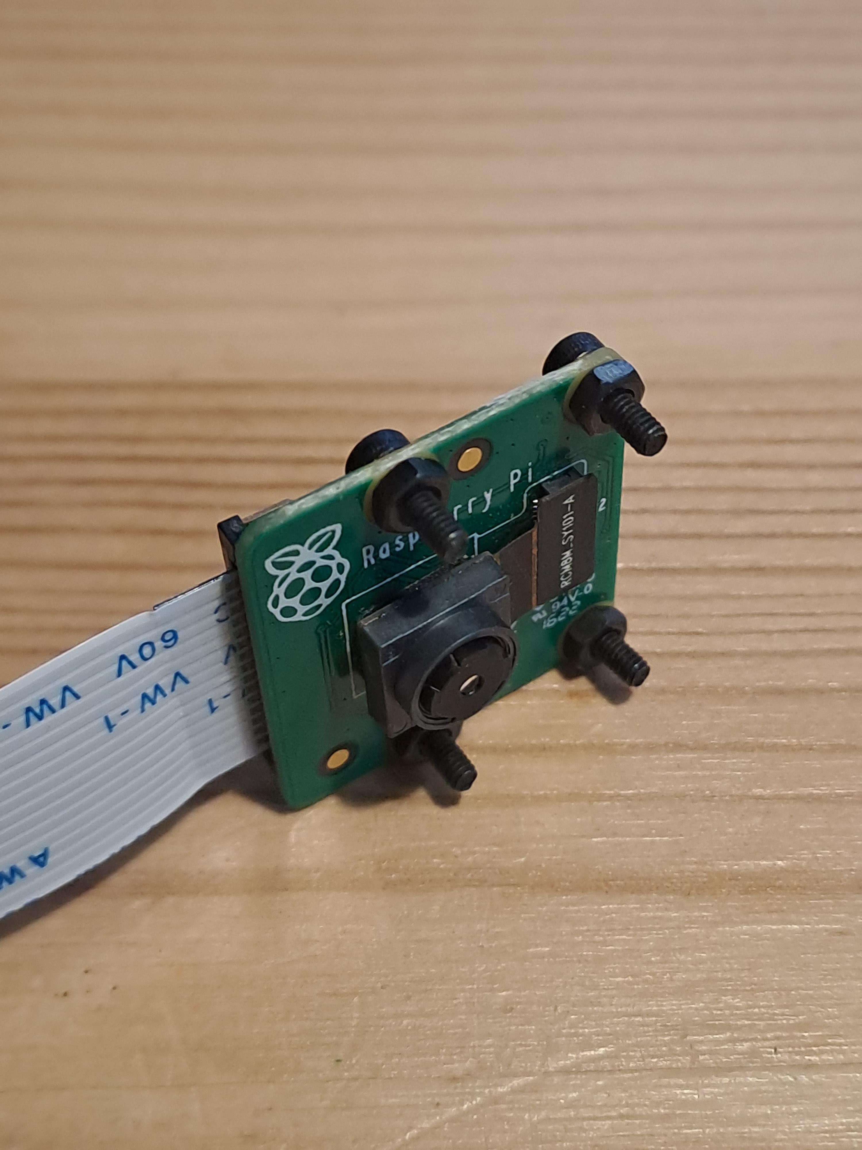
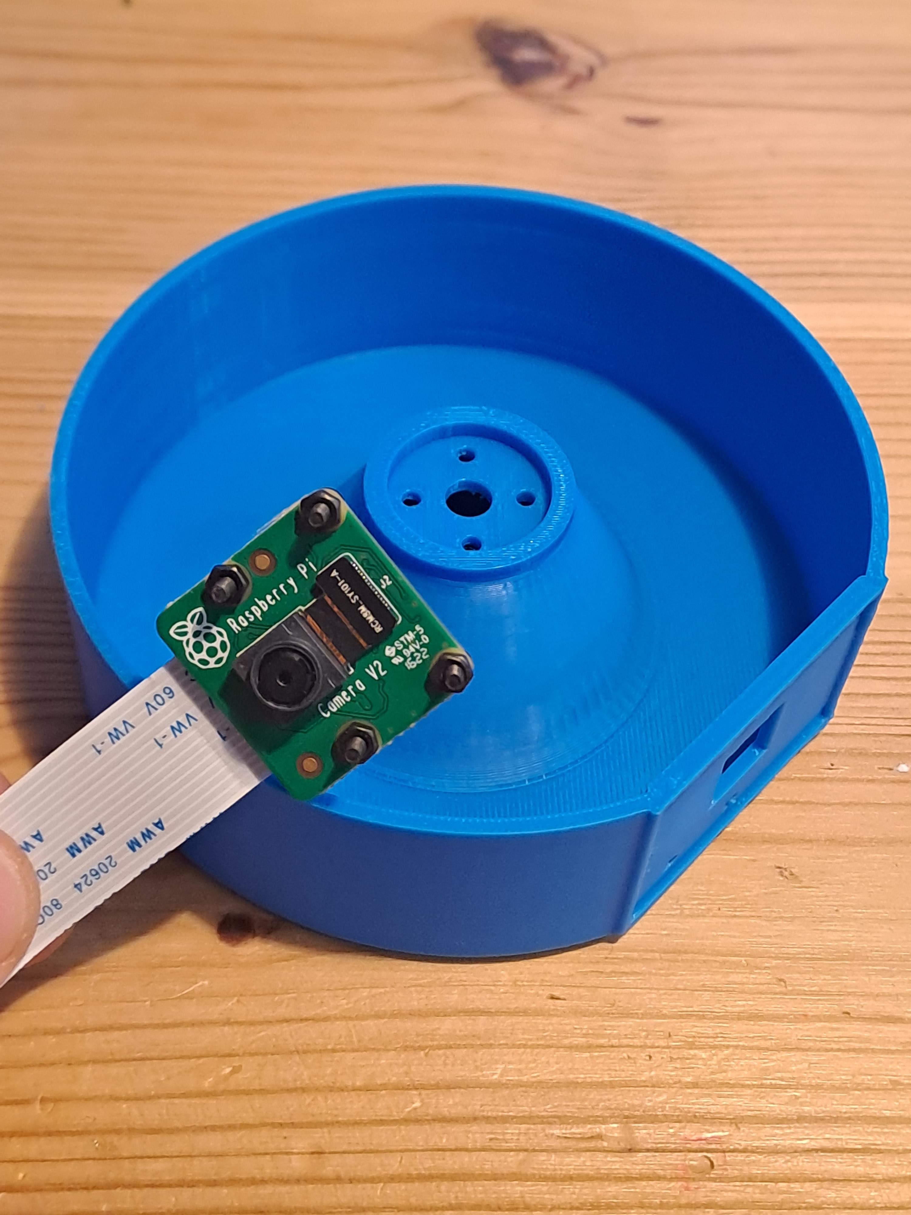
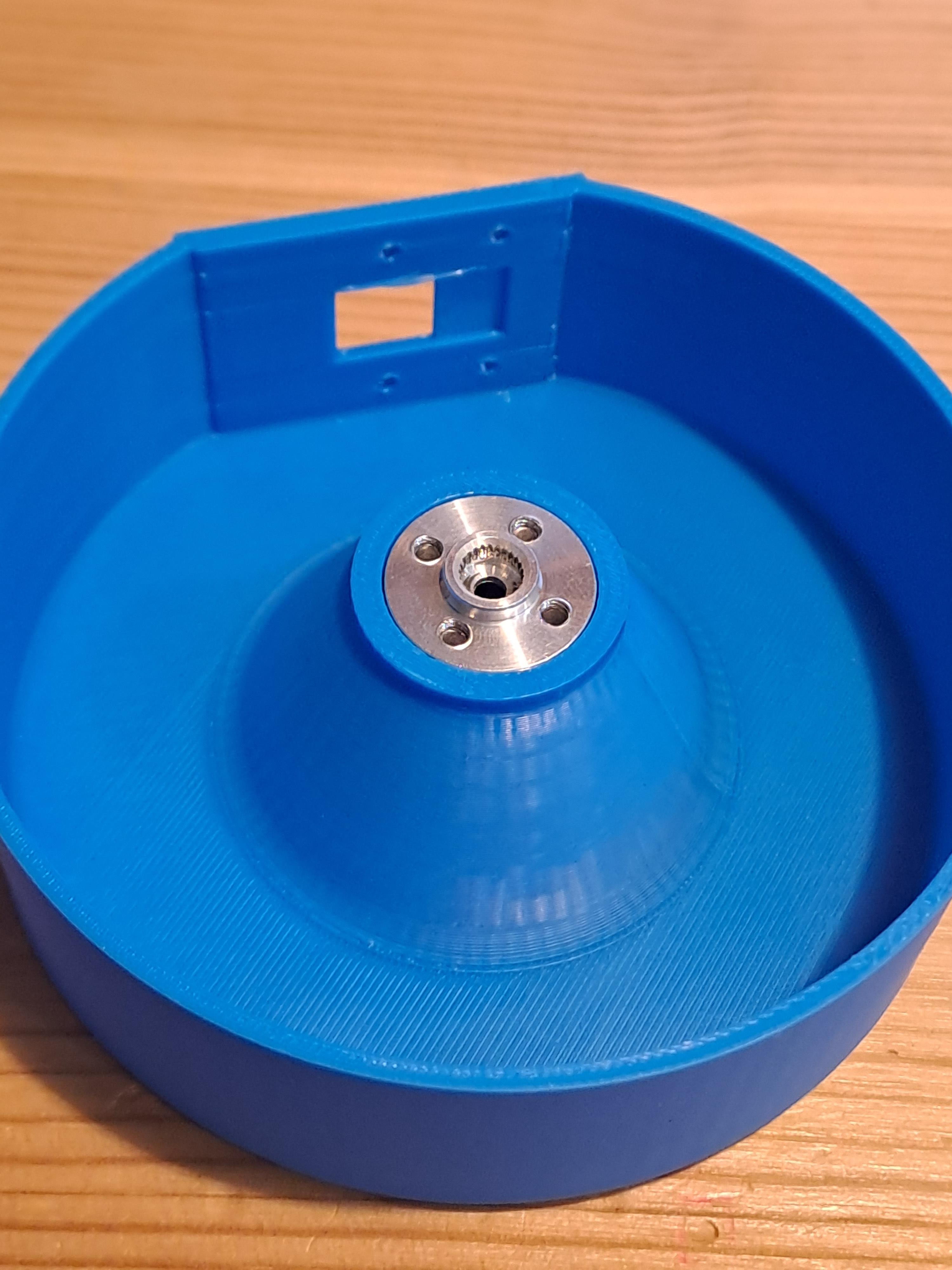
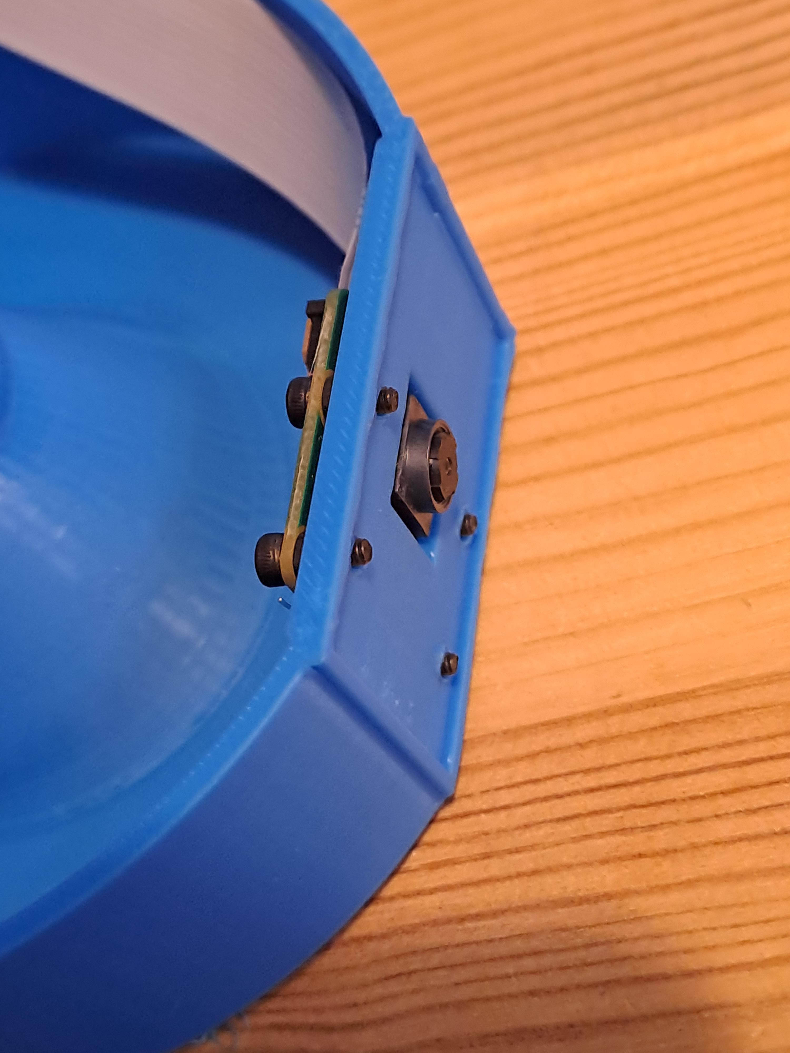
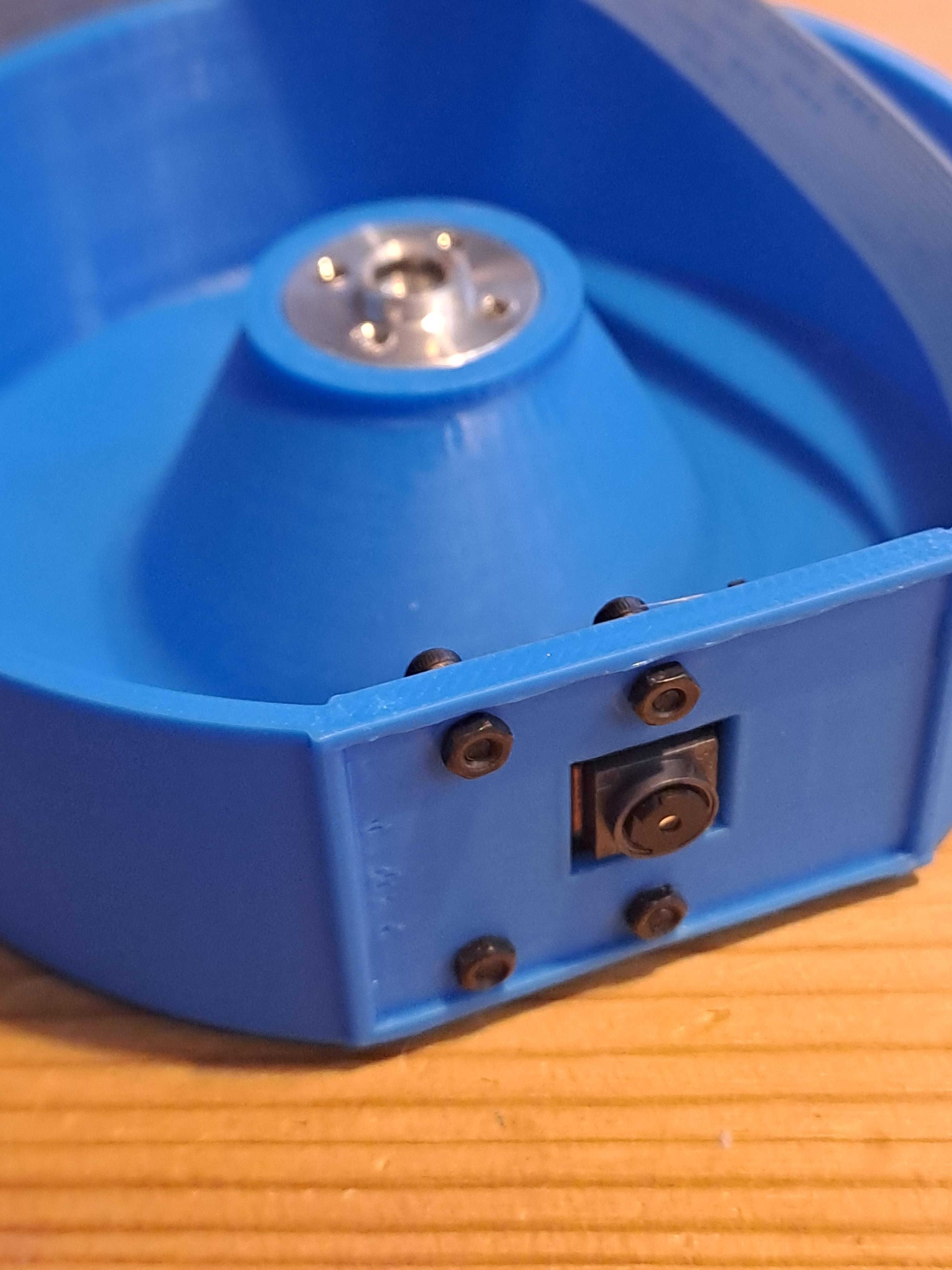
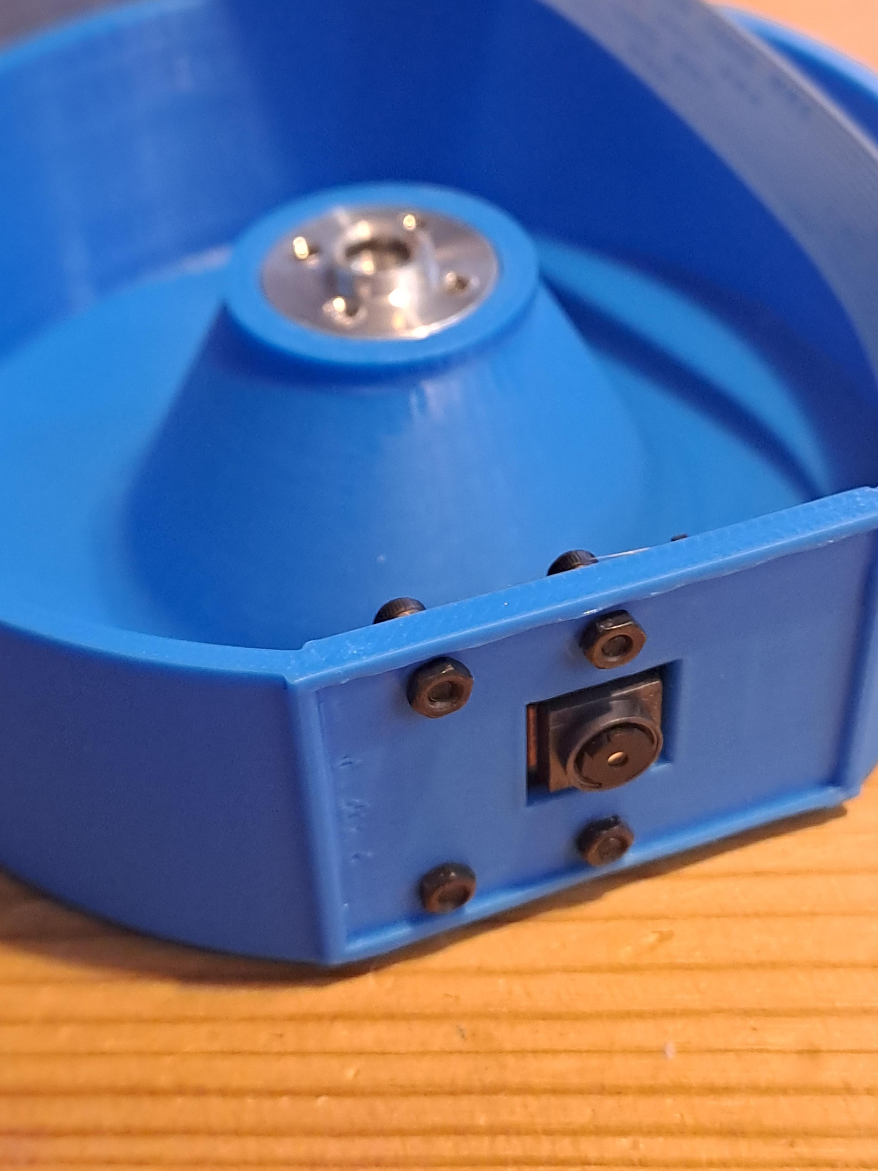
- Attach the ribbon cable to the camera module carefully. The sockets for these ribbon cables break very easily (trust me on that!) be very careful.
- Secure the camera to the aluminum disk.
- Mount it onto the 3D-printed camera wheel.
Install Camera Wheel
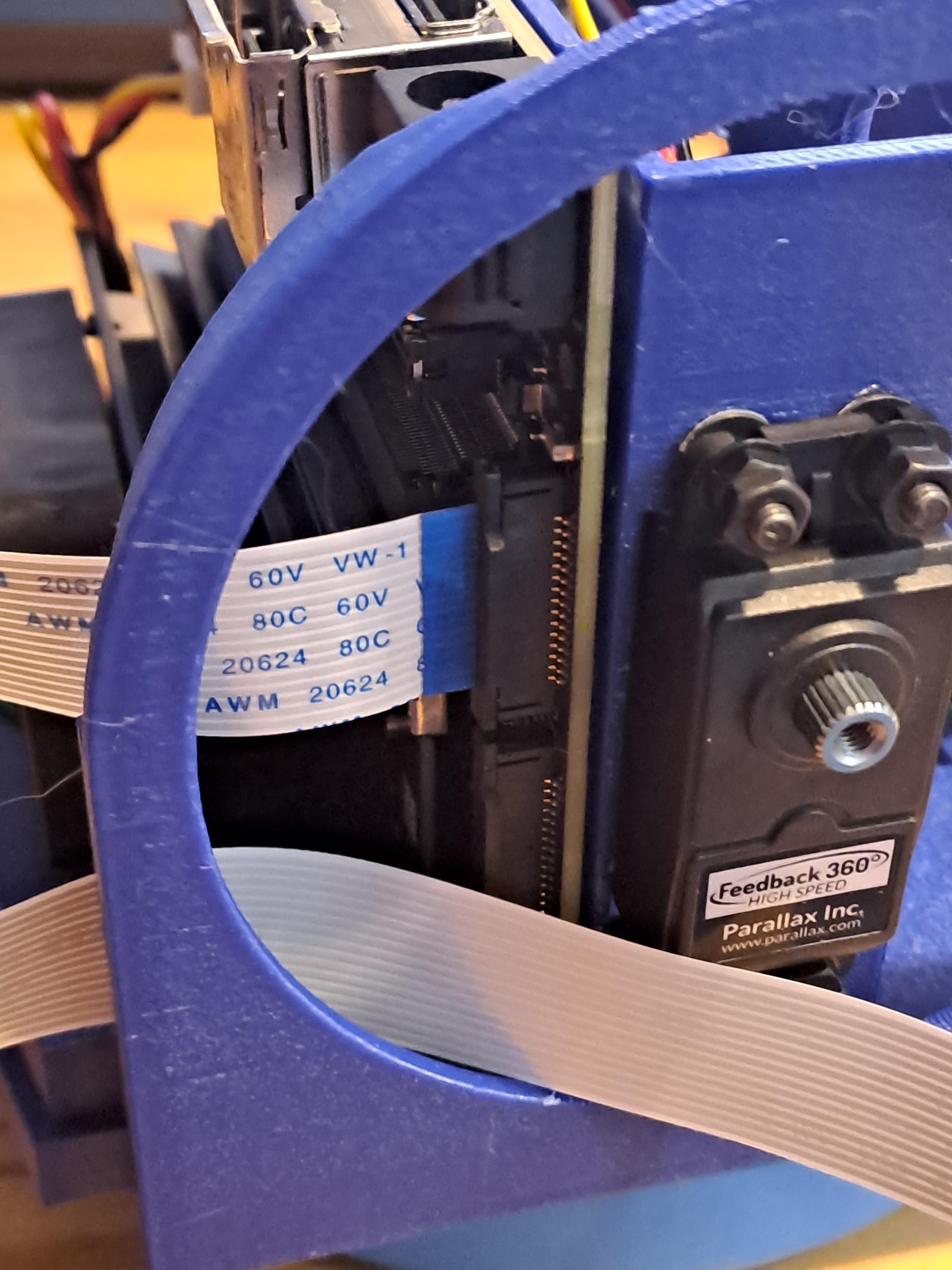
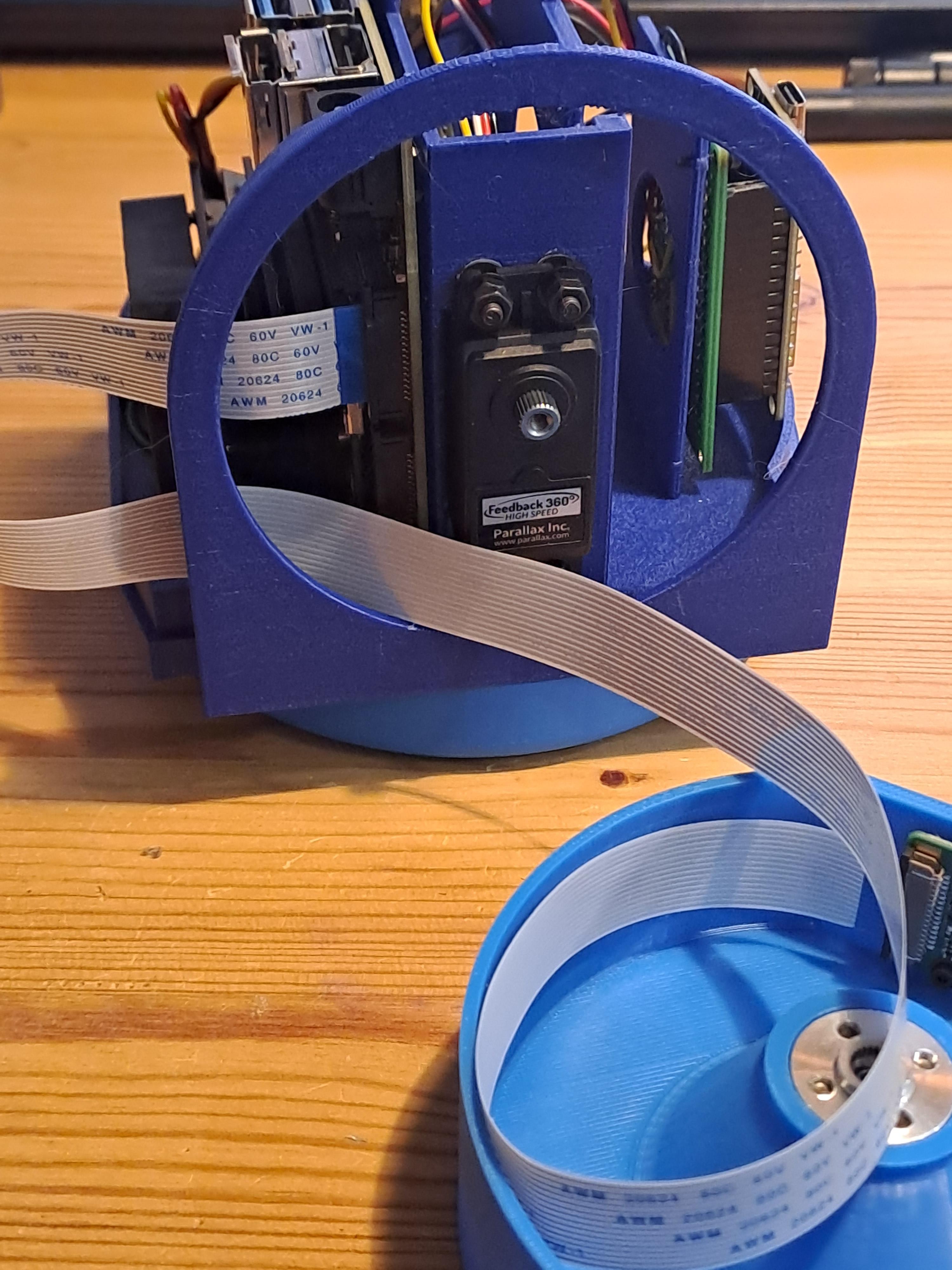
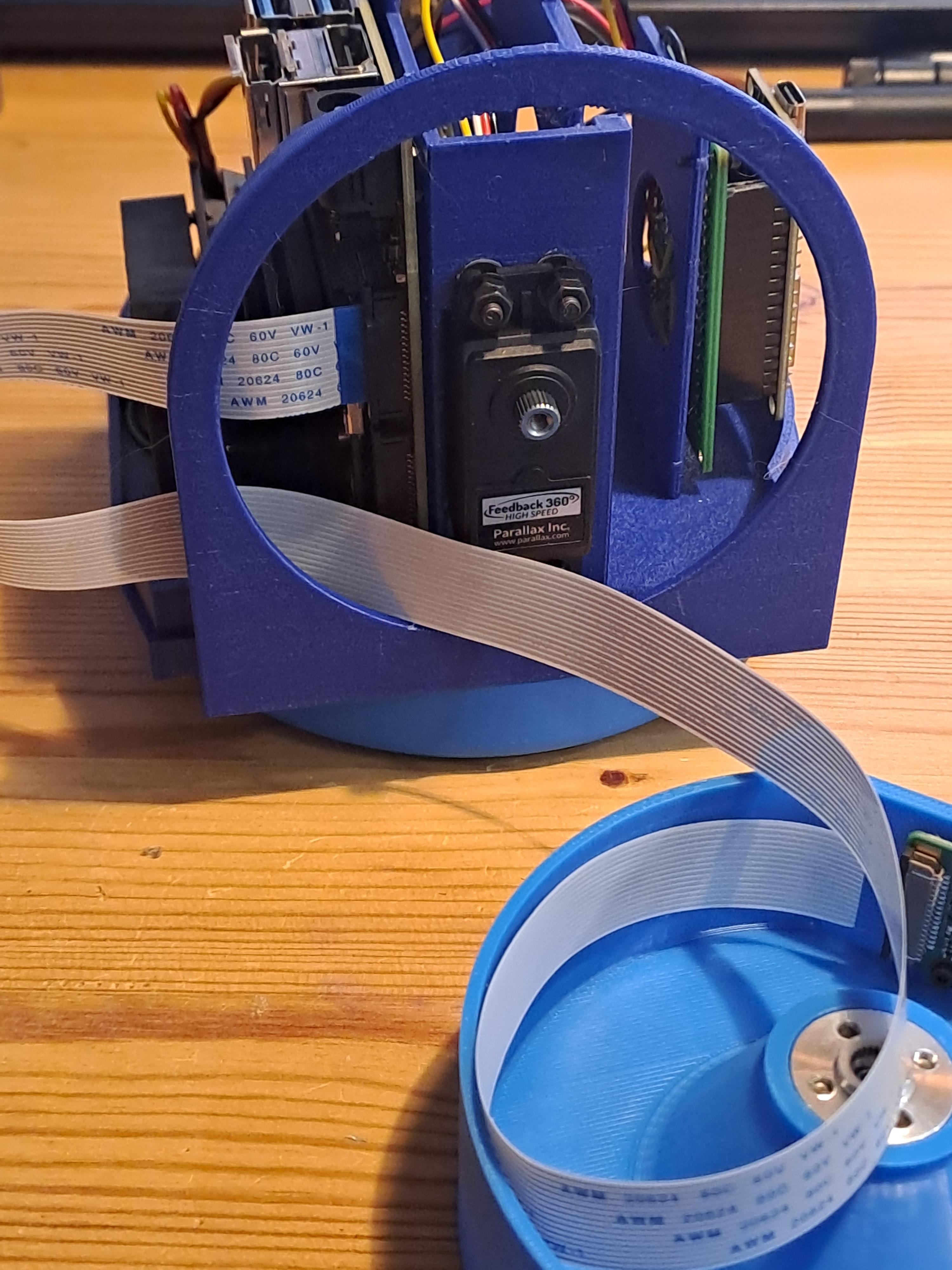
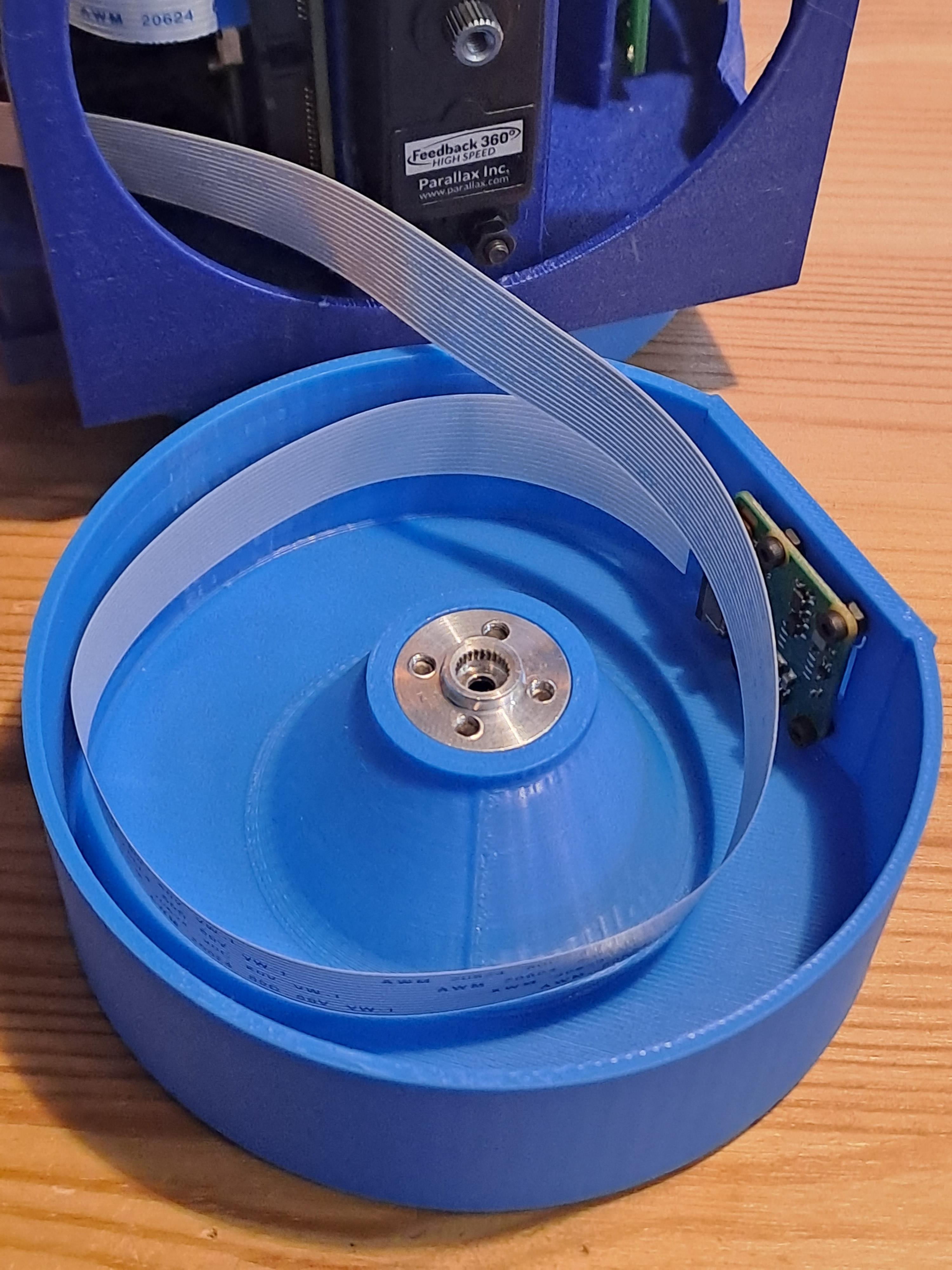
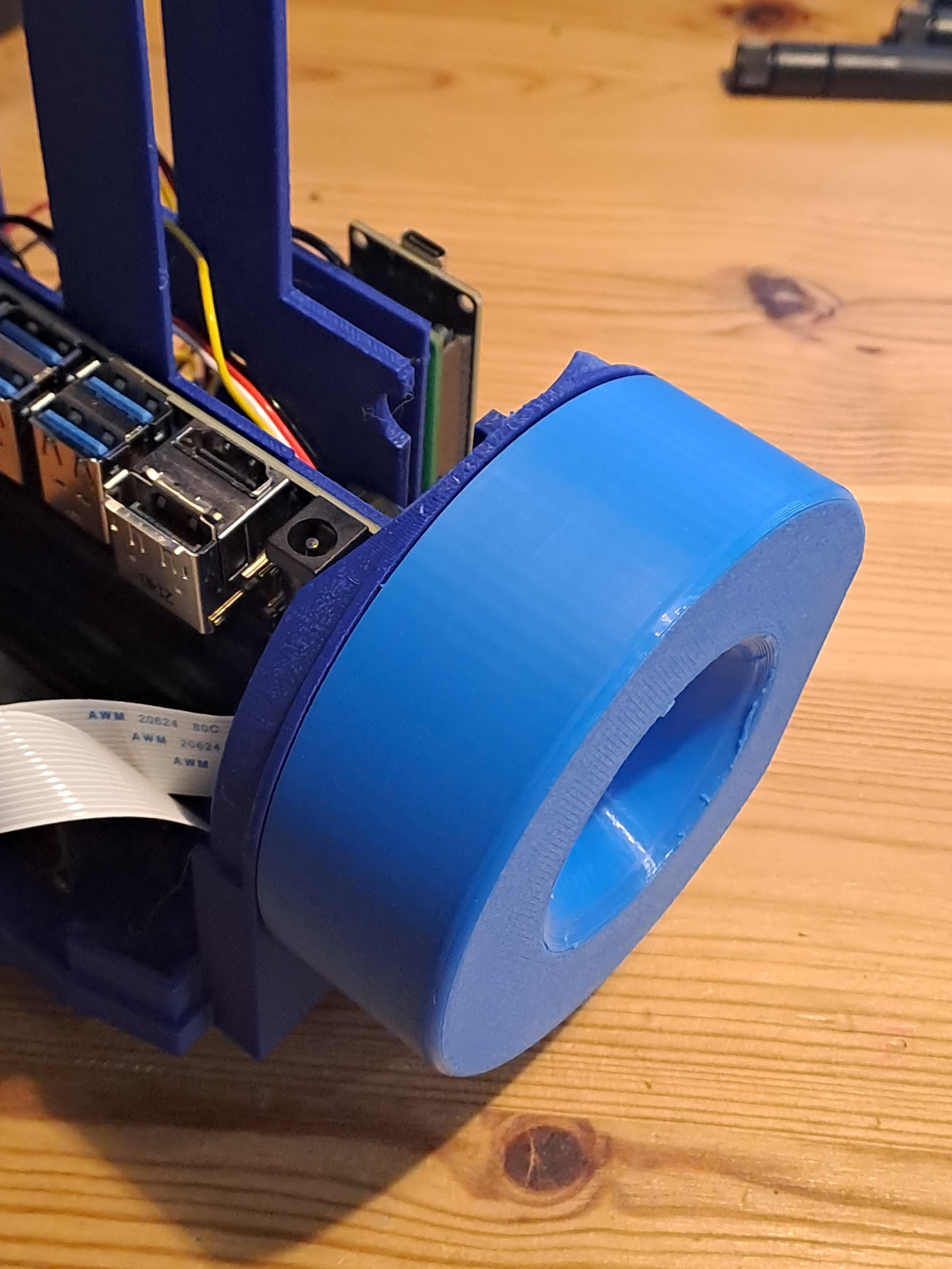
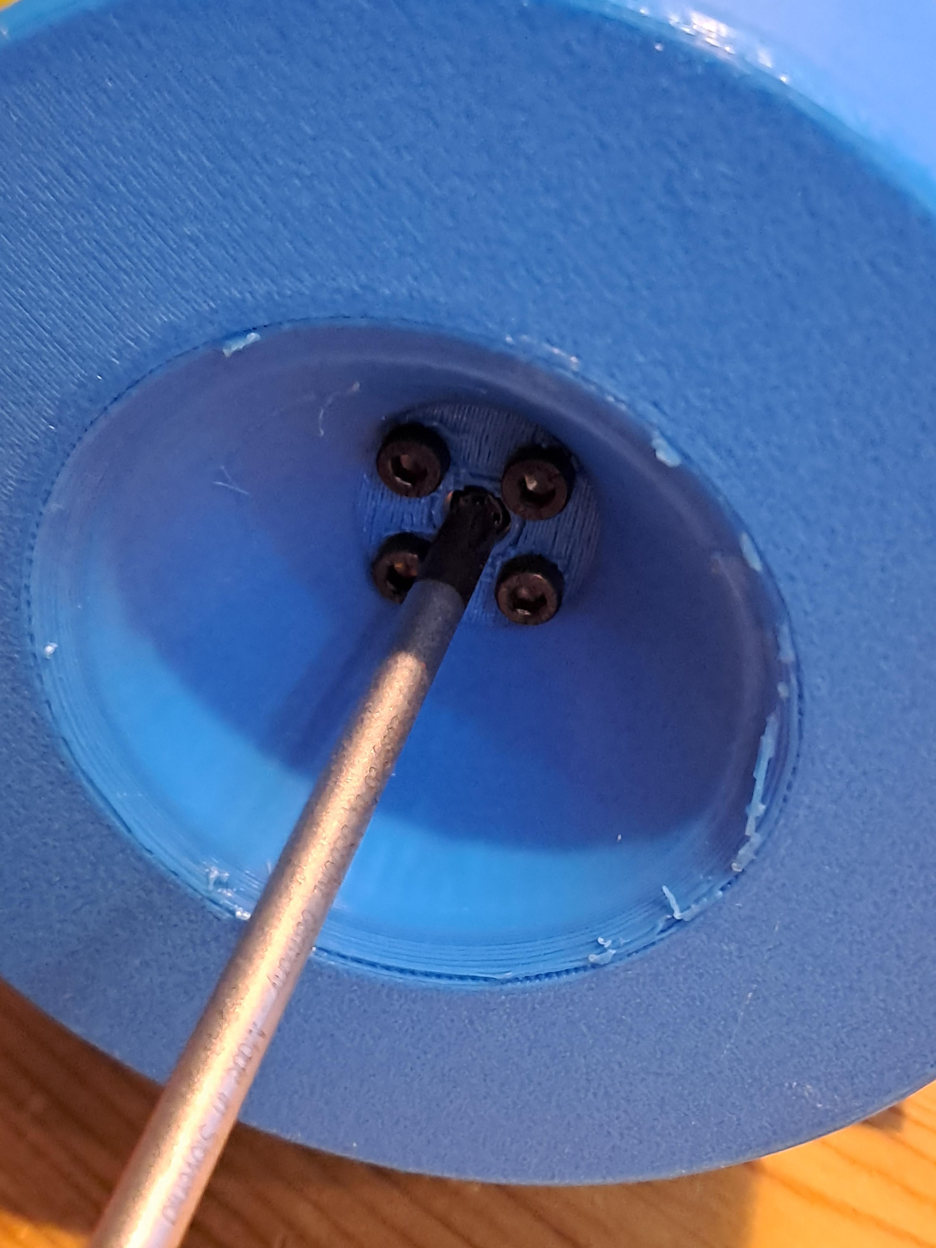
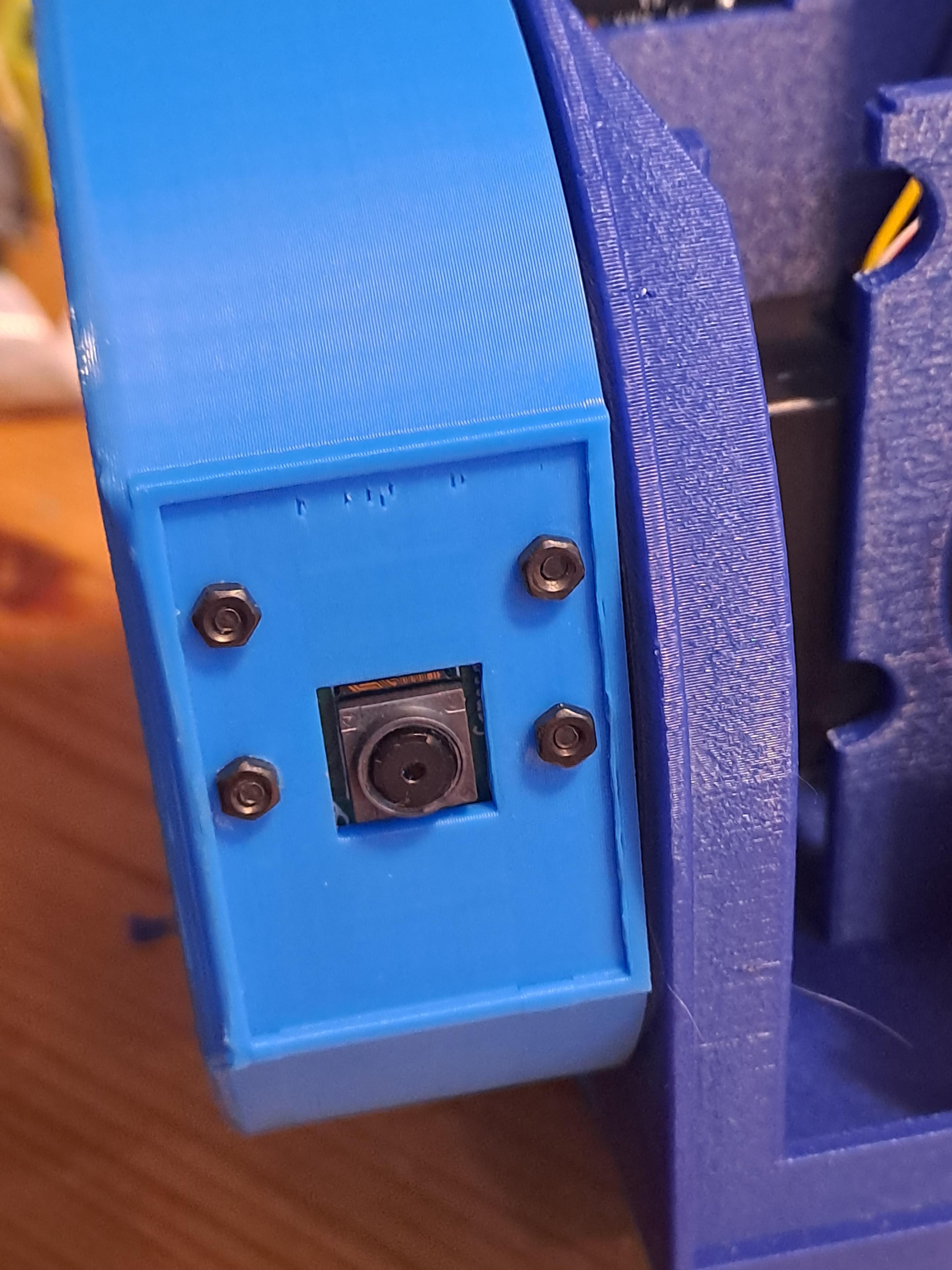
- Connect the ribbon cable to the Jetson Nano board. Again, be careful with the ribbon cables.
- Have a look of how I organize the ribbon calble in the camera wheel.
- Use a screw to attach the camera wheel to the servo. This time it is good to connect the ESP32 shortly so that the servo goes to a default position of 15 degrees. This way you can already place the camera in a 90 degre angle looking forward.
- Test the camera wheel’s rotation manually and carefully, ensuring the ribbon cable does not entangle or stretch.
- Aim for at least three full rotations. Make sure this works well.
Connect to ESP32
Time to interface with external hardware. Connect the USB port of the ESP32 to the USB port of the Jetson Nano for a test. Start up the Jetson Nano and connect remotely:
- 🔍 Detect the ESP32:
2. Enable User Access:
3.🔧 Set Permissions:
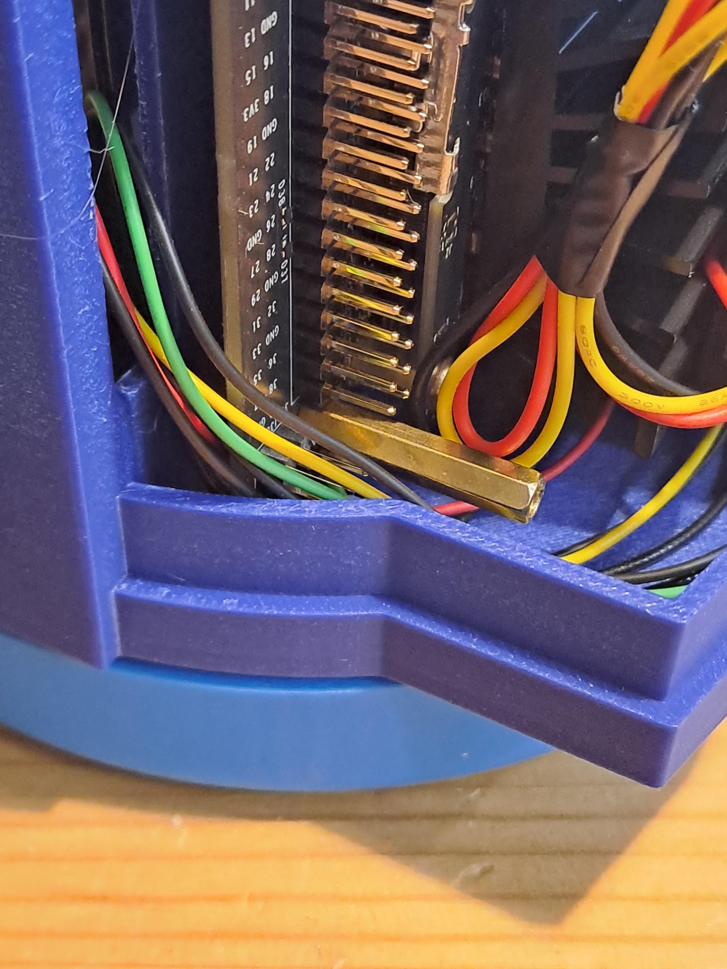
Organize Cables and Install Jetson Nano
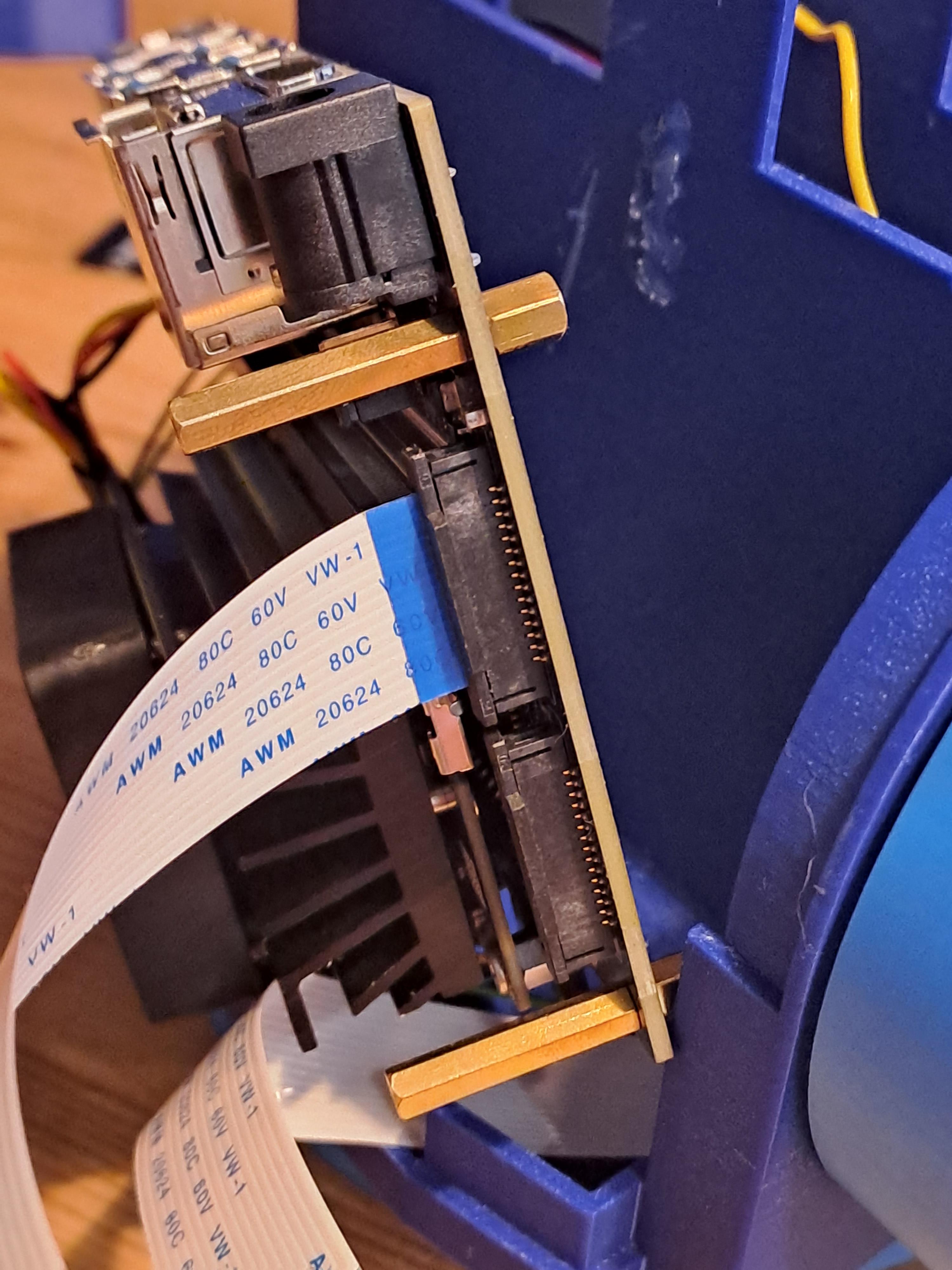
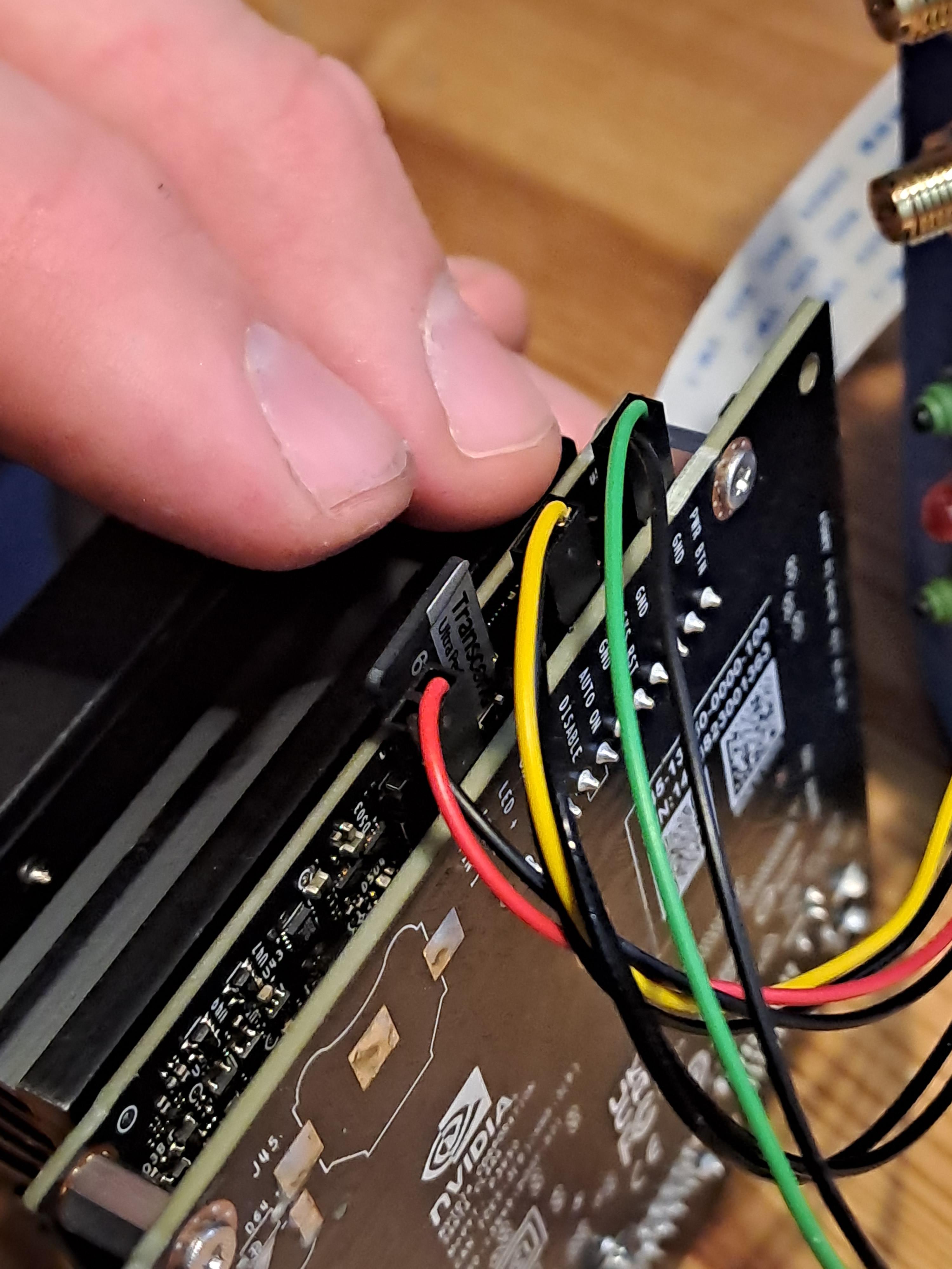
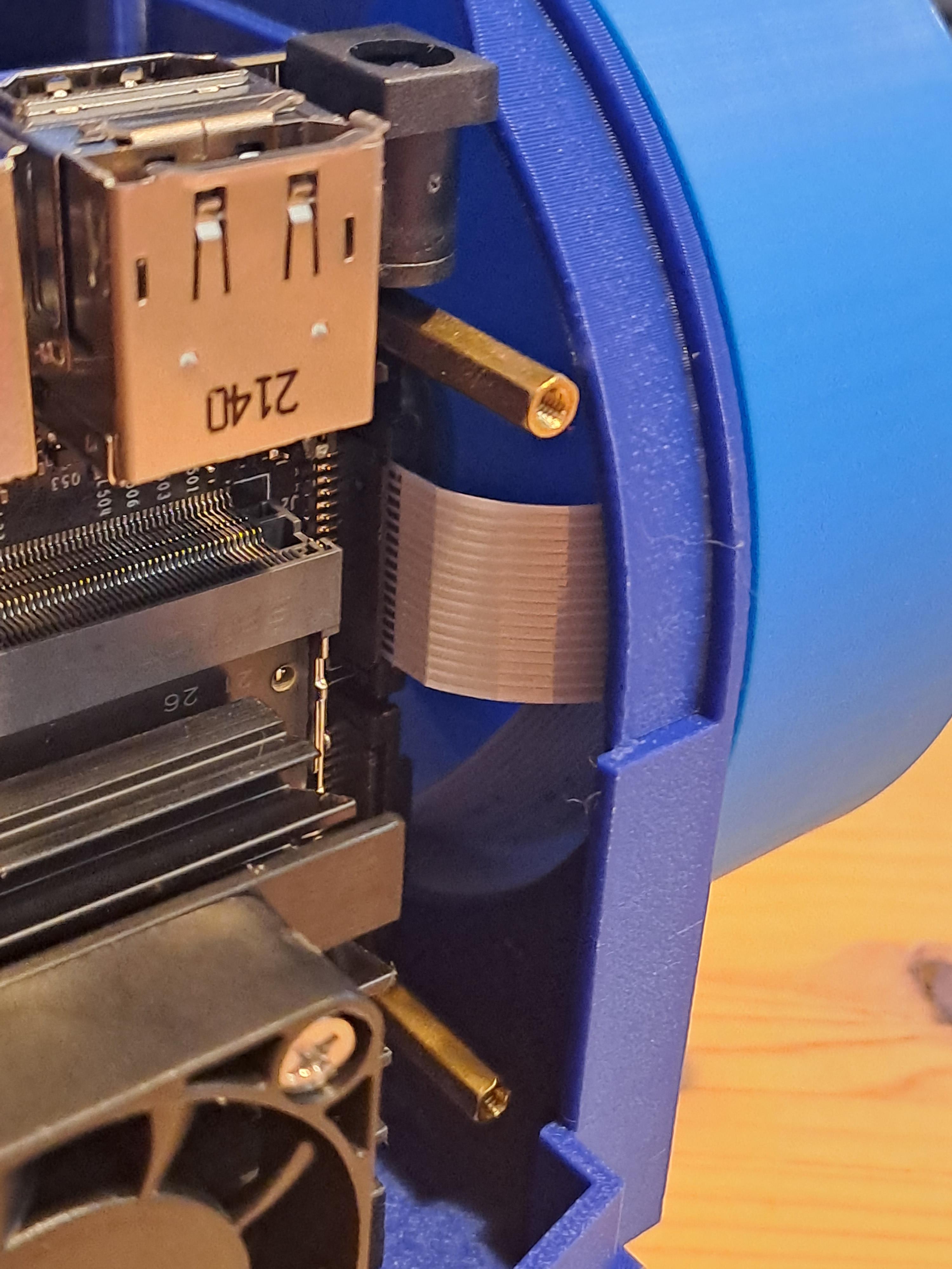
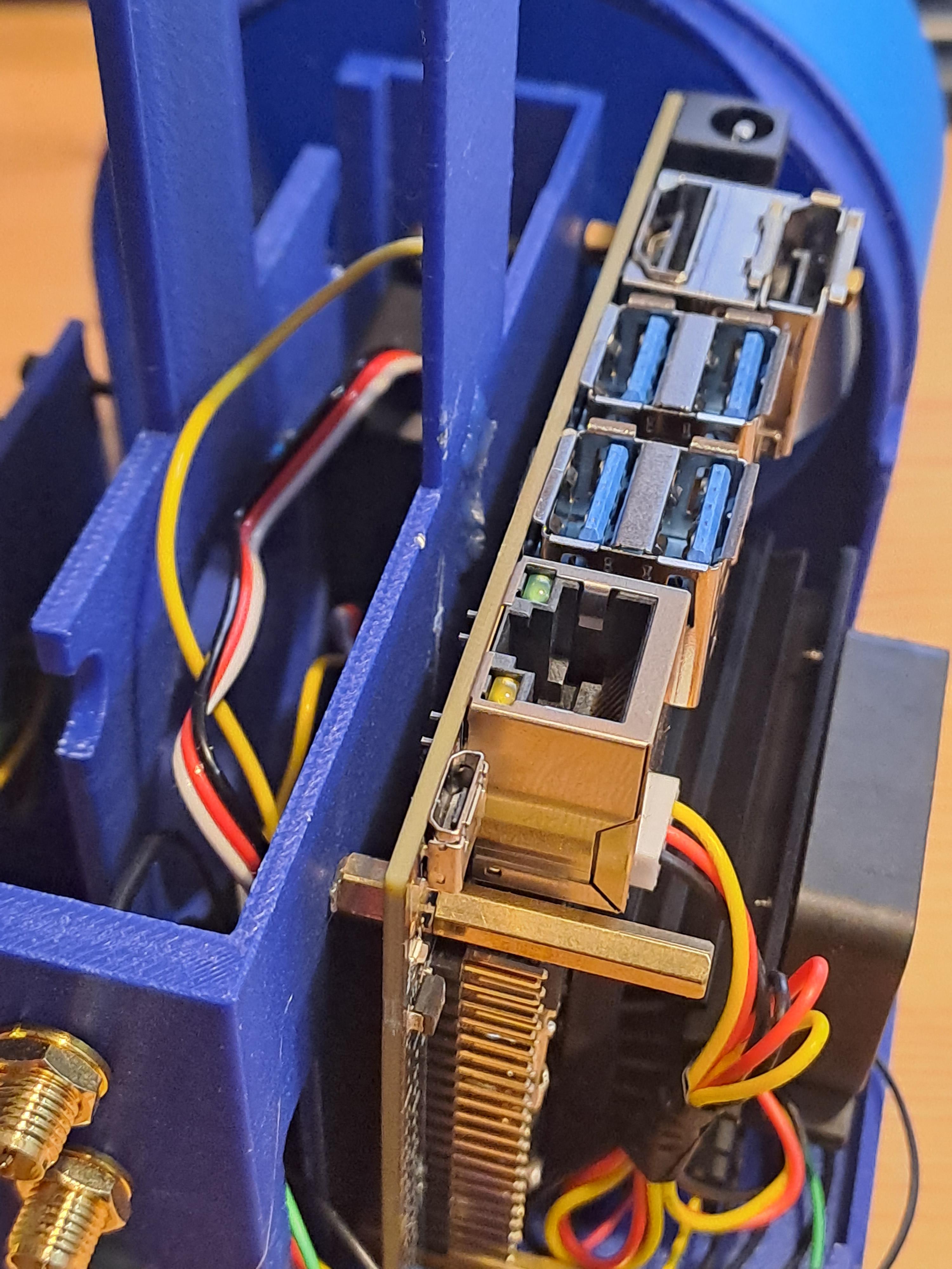
- Neatly organize all cables to avoid tangles.
- Mount the Jetson Nano using spacers, ensuring it fits snugly. If necessary, adjust cable placements underneath the board.
Keep Organizing Cables
Add Powerbank and Connect Power Supply
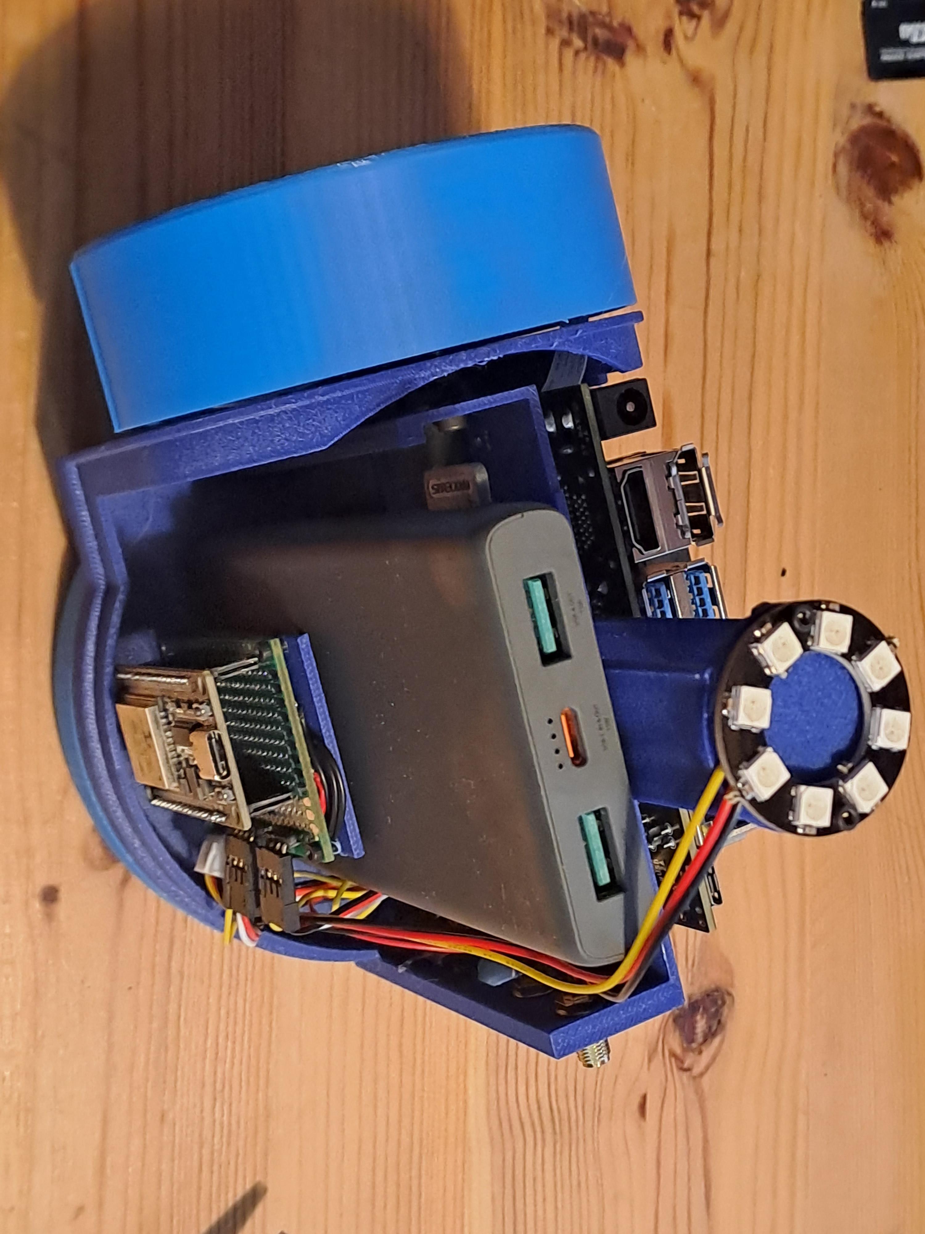
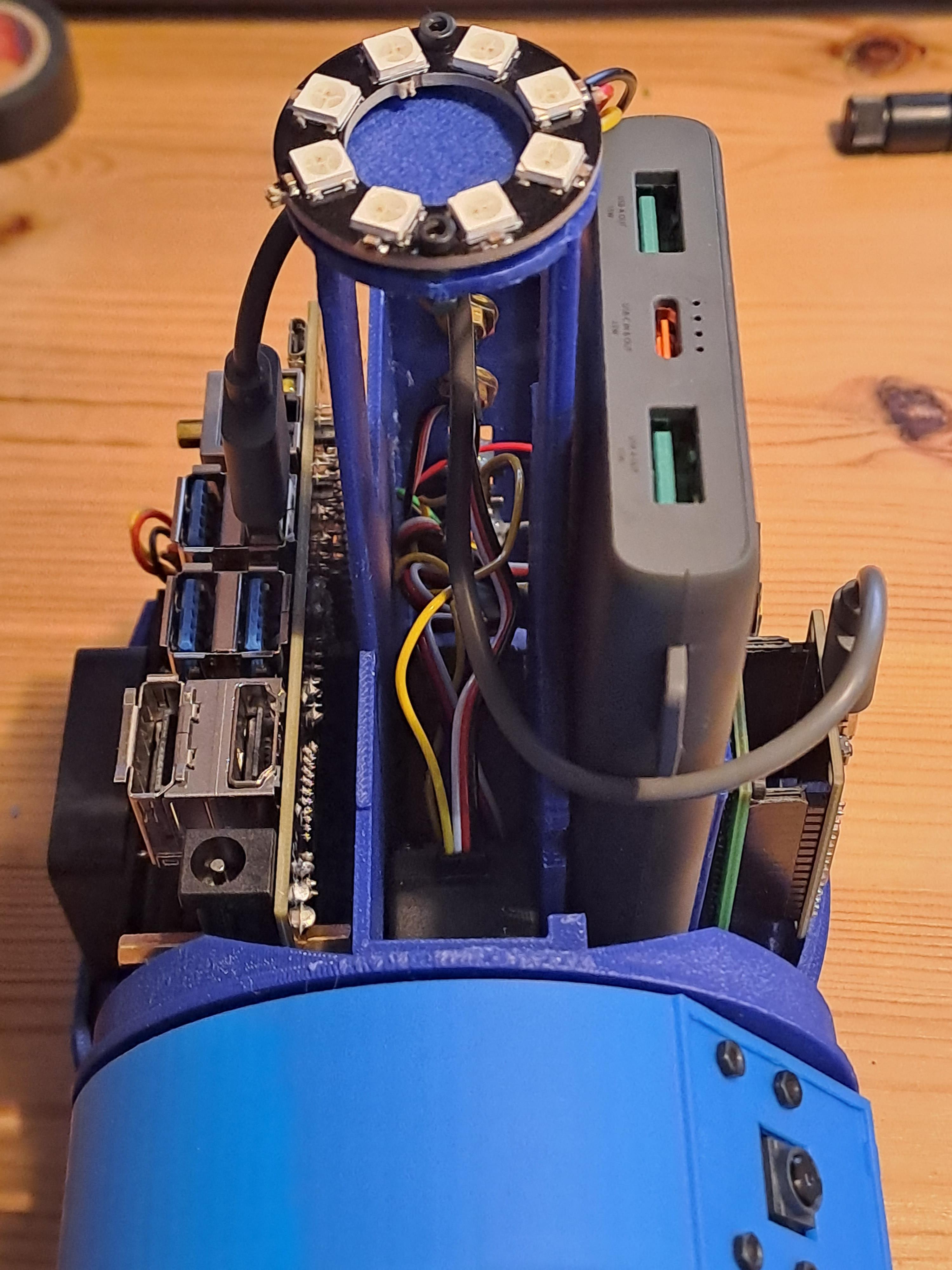
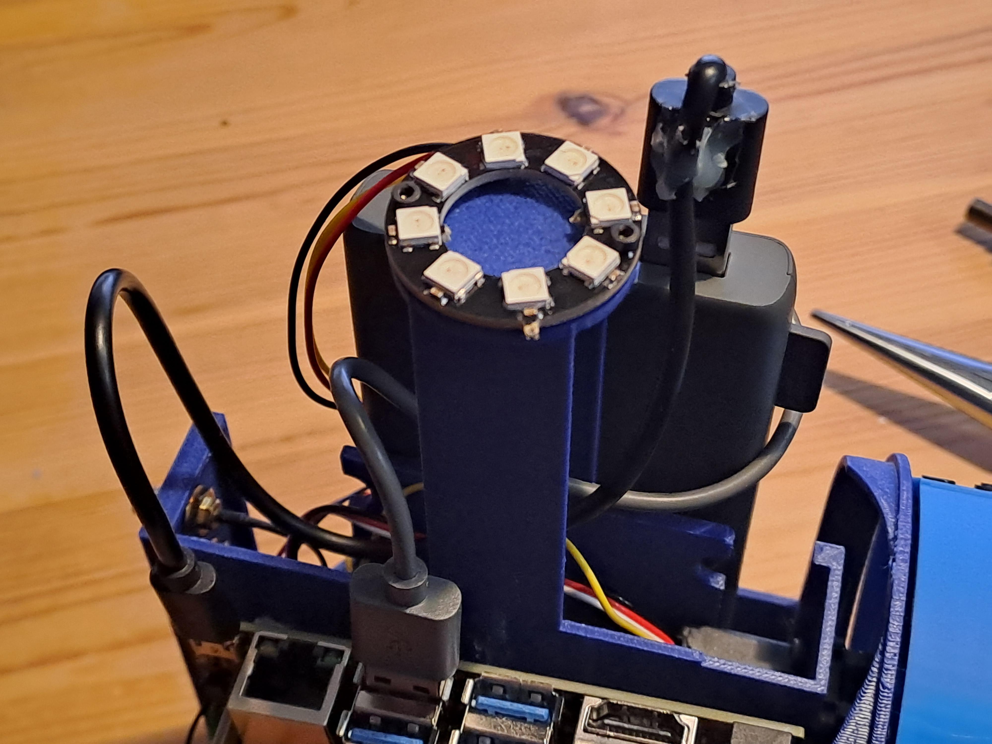
- Place the power bank in its compartment and secure it with rubber bands.
- Connect the power supply to the Jetson Nano.
Add USB Stick for Image Storage
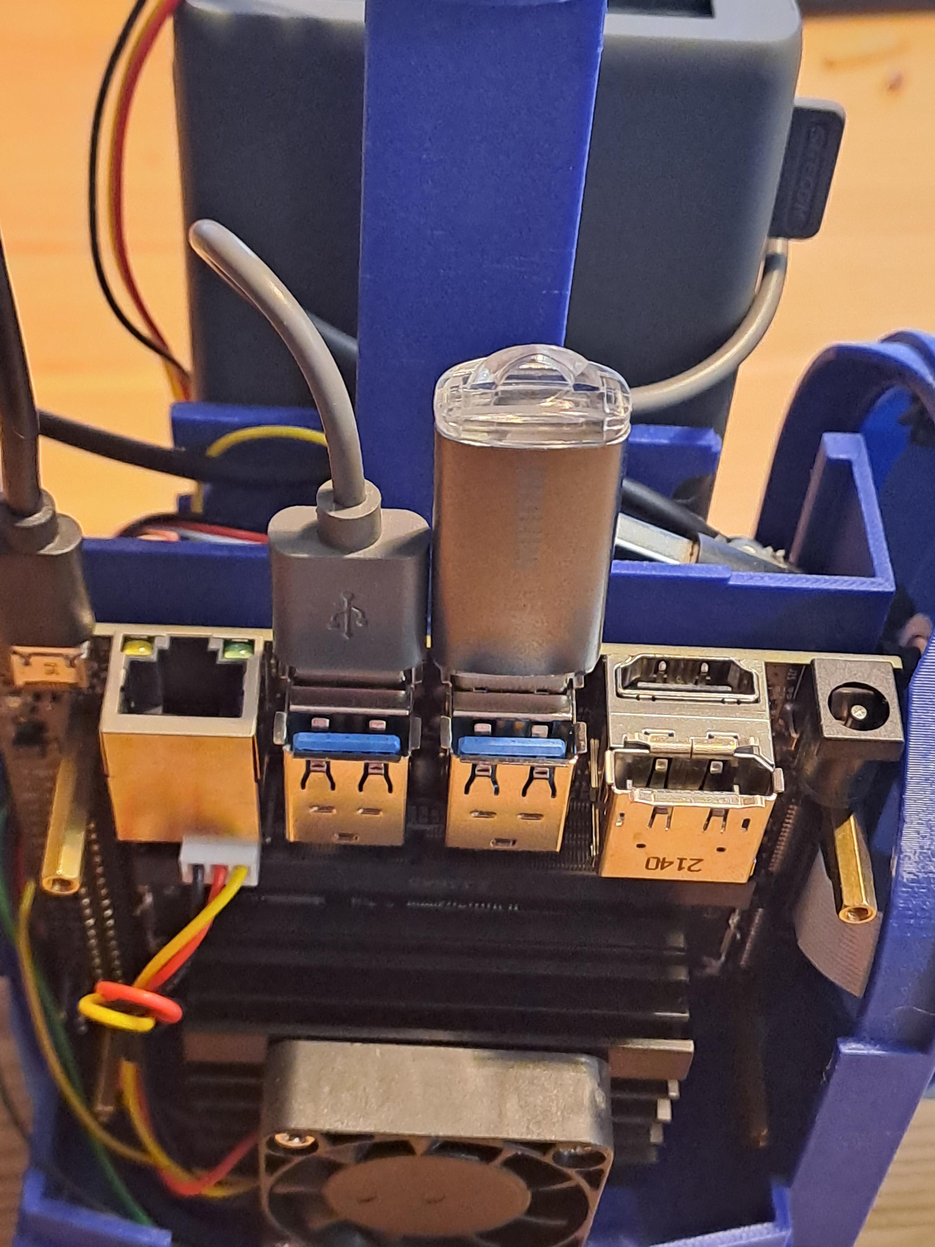
This is optional. Name the USB stick "VT360". The code on the Jetson Nano will later look for a pen drive or USB stick that is attached to the USB ports named "VT360". If none with this name is there, it will just safe the images on the SD card.
Prepare and Install Dome
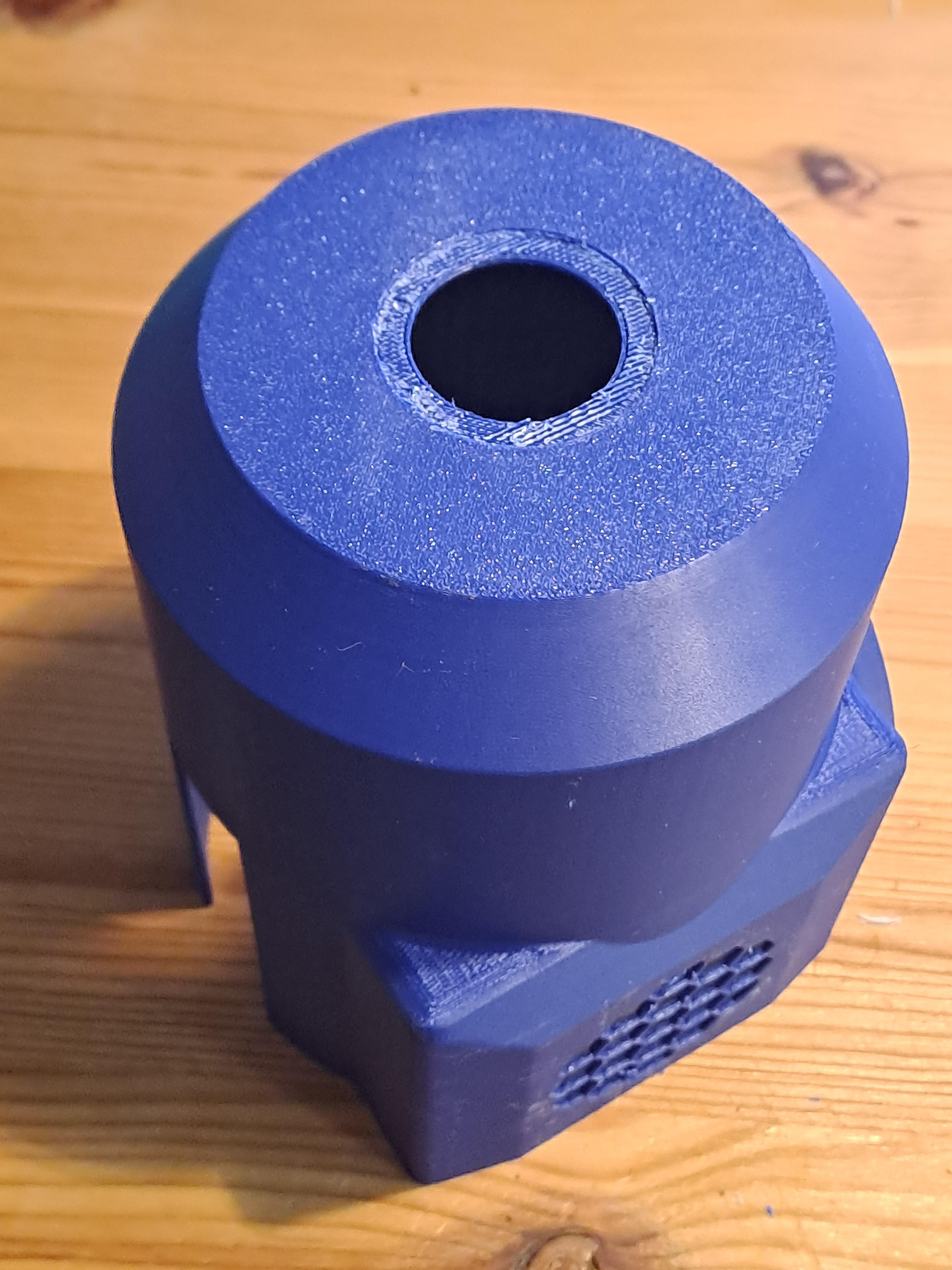
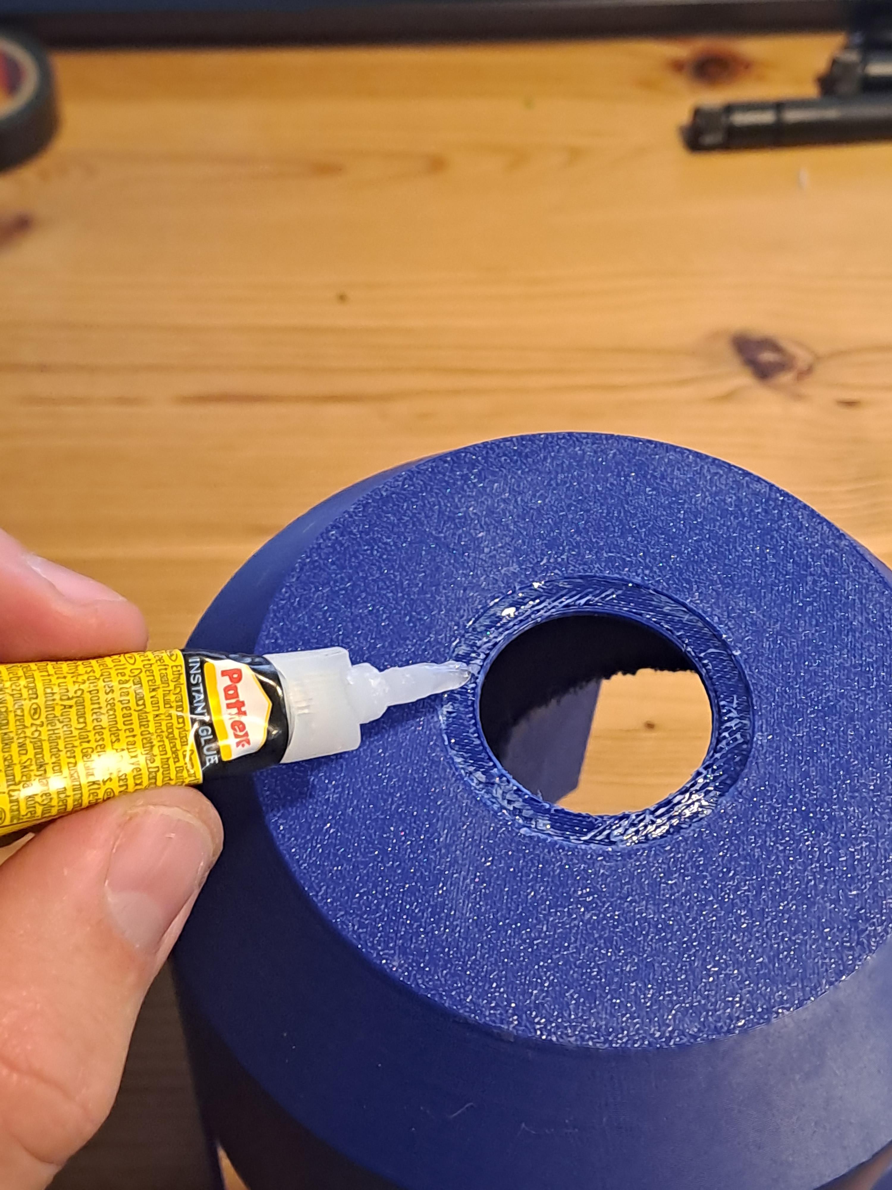
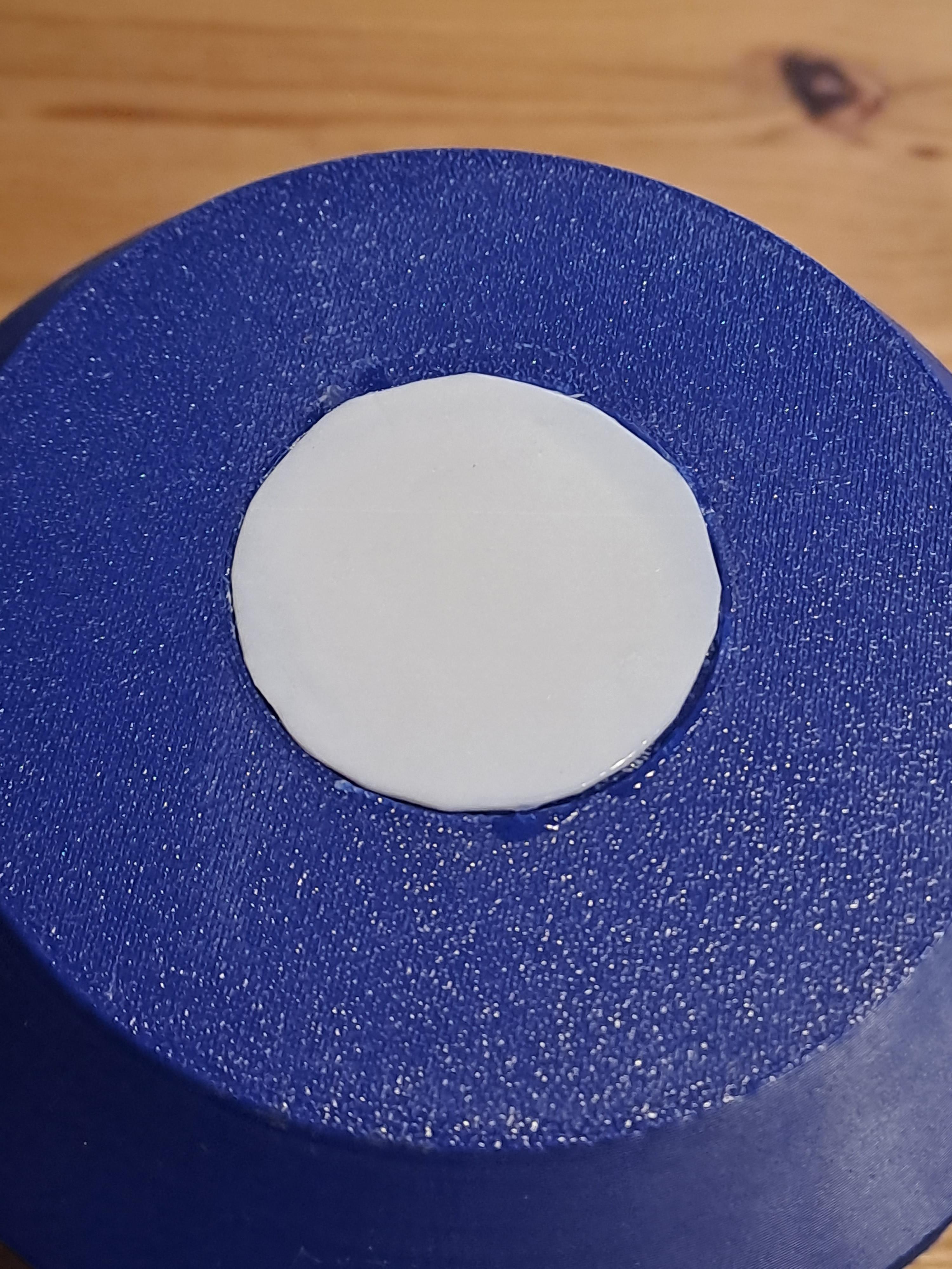
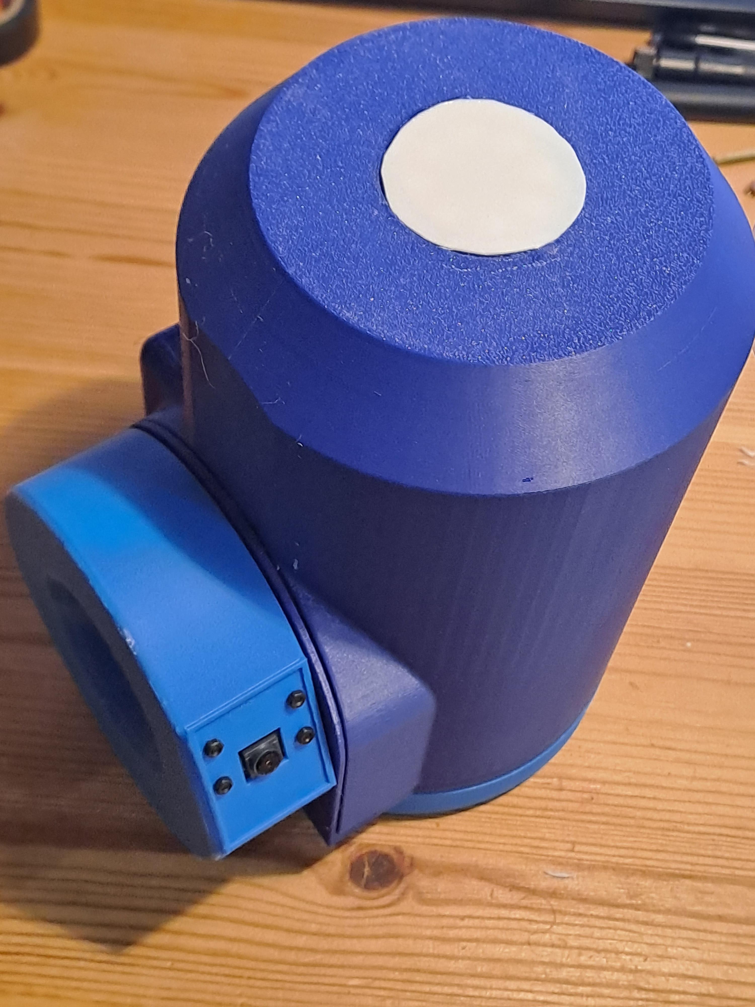
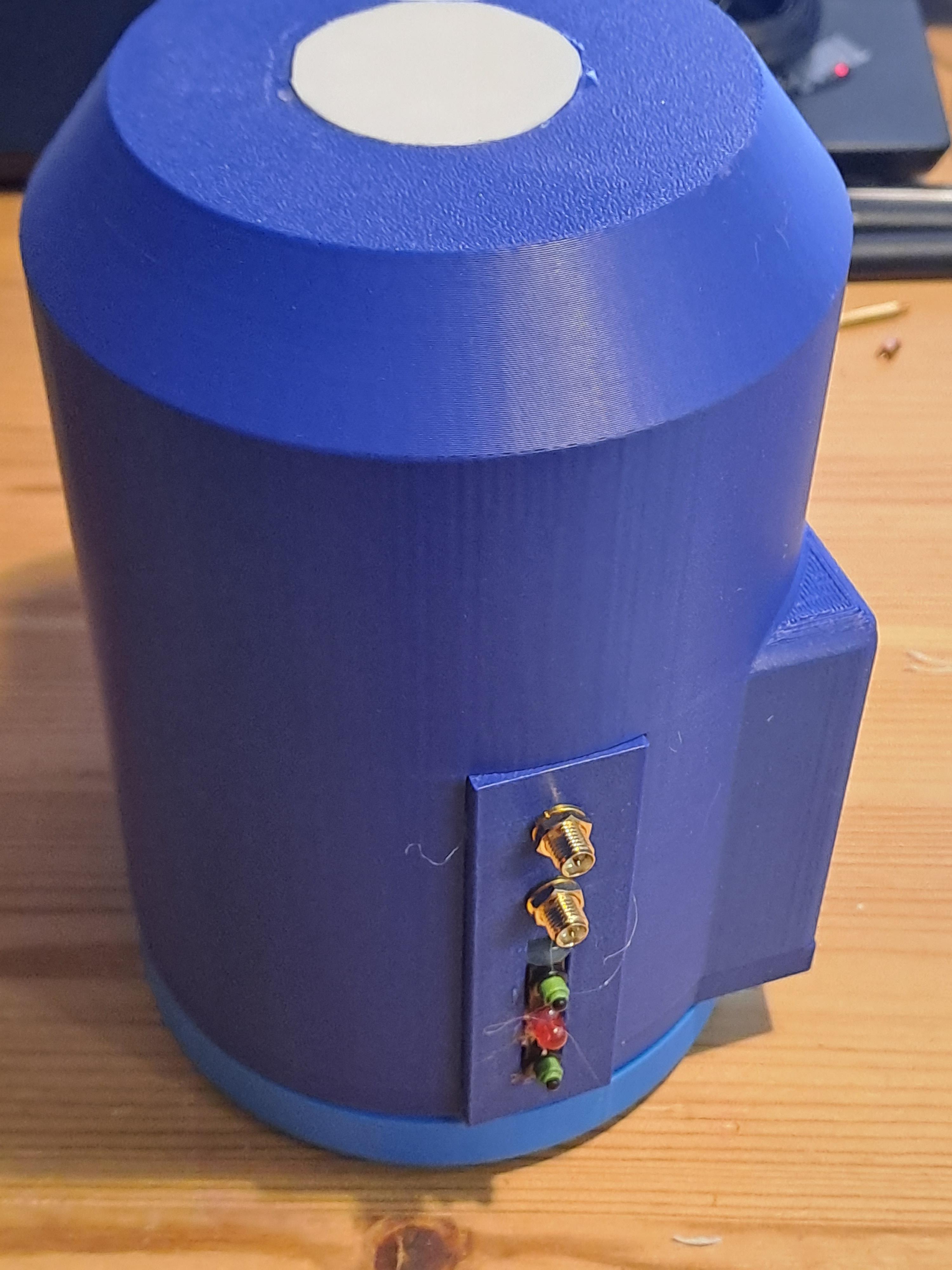
- Glue the Teflon diffuser disk onto the dome.
- Slide the dome onto the main assembly. This should work perfectly if you have a proper cable management.
Add WiFi Antennas
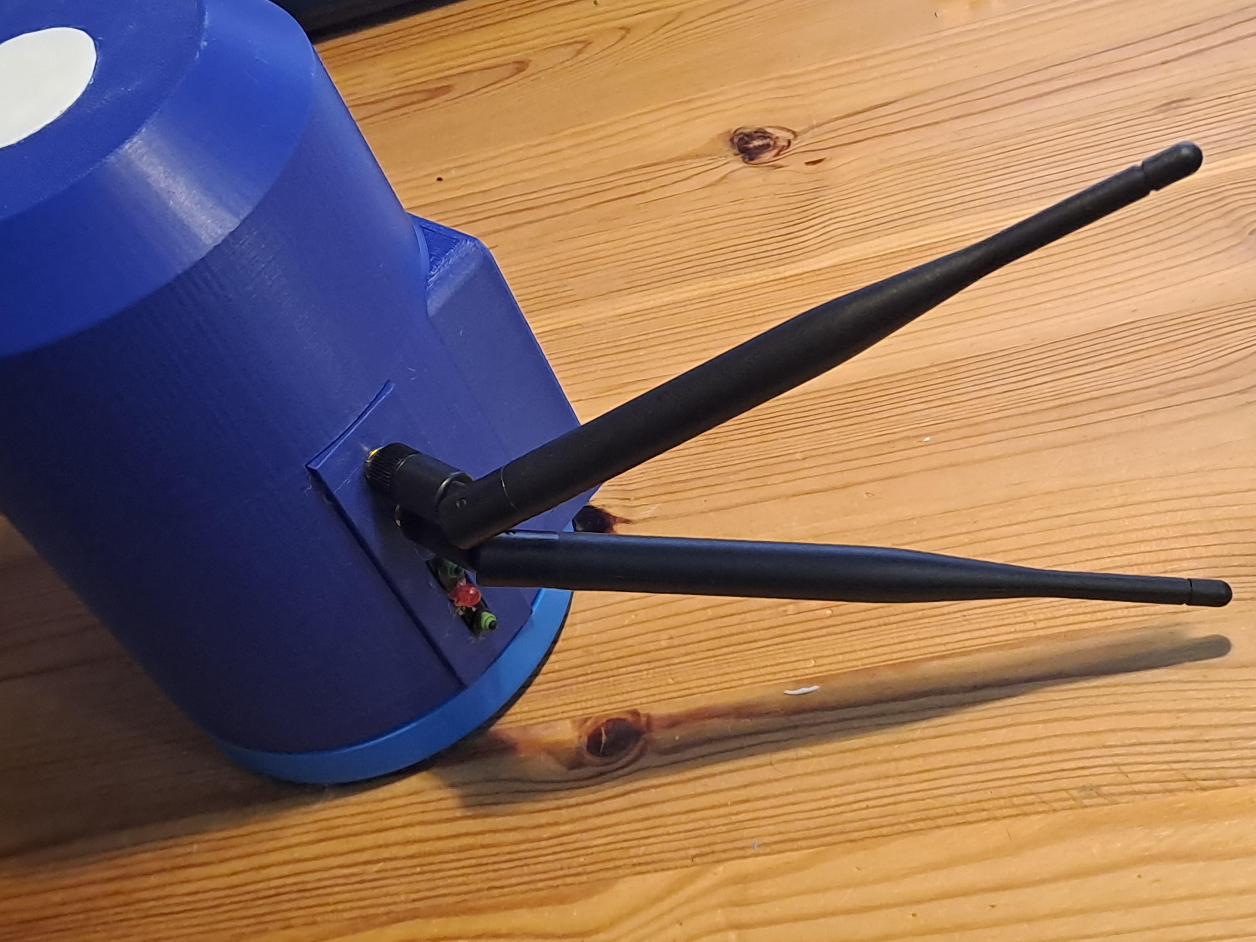
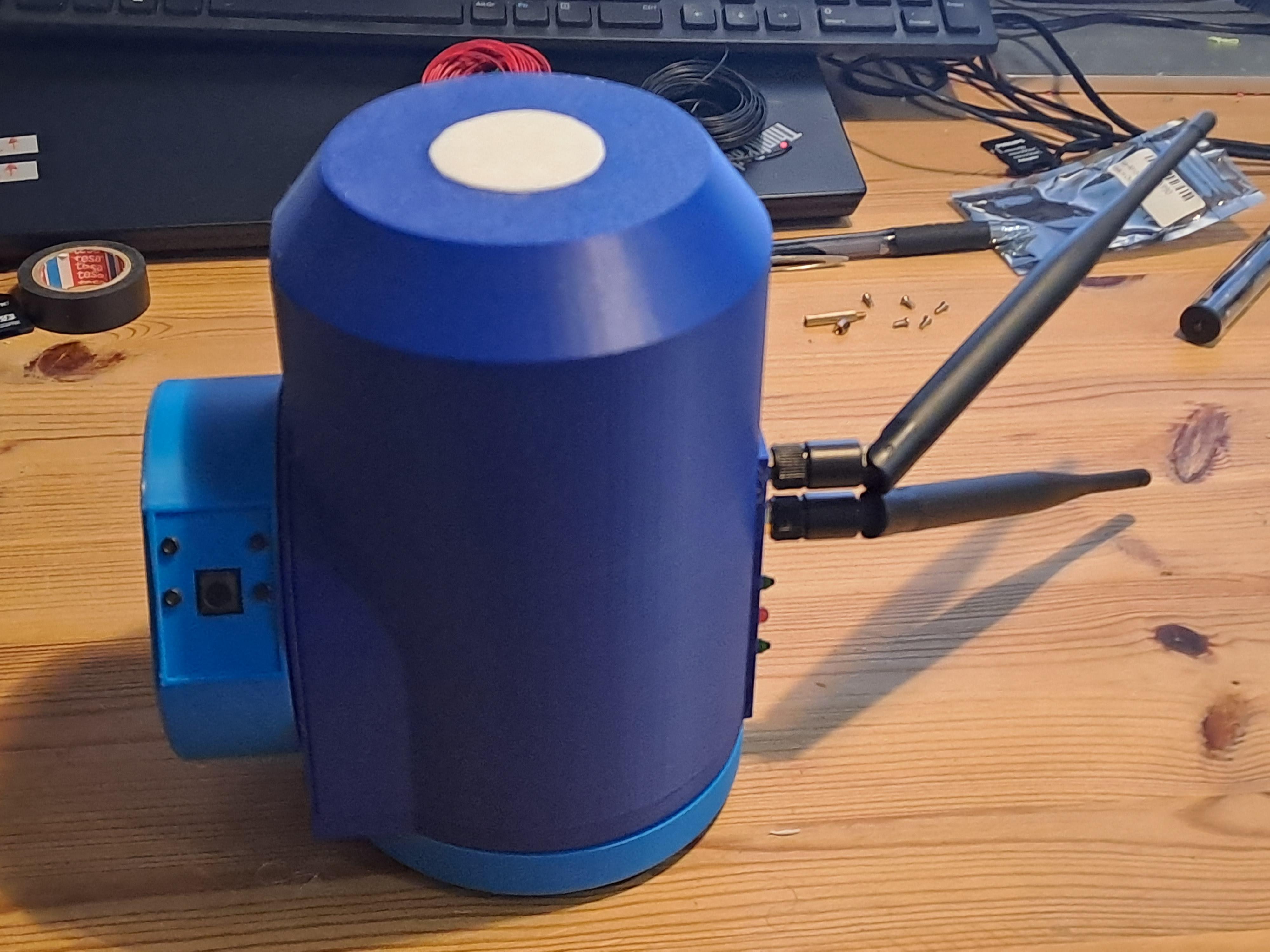
- Screw the WiFi antennas onto the installed sockets.
You Are Almost There!
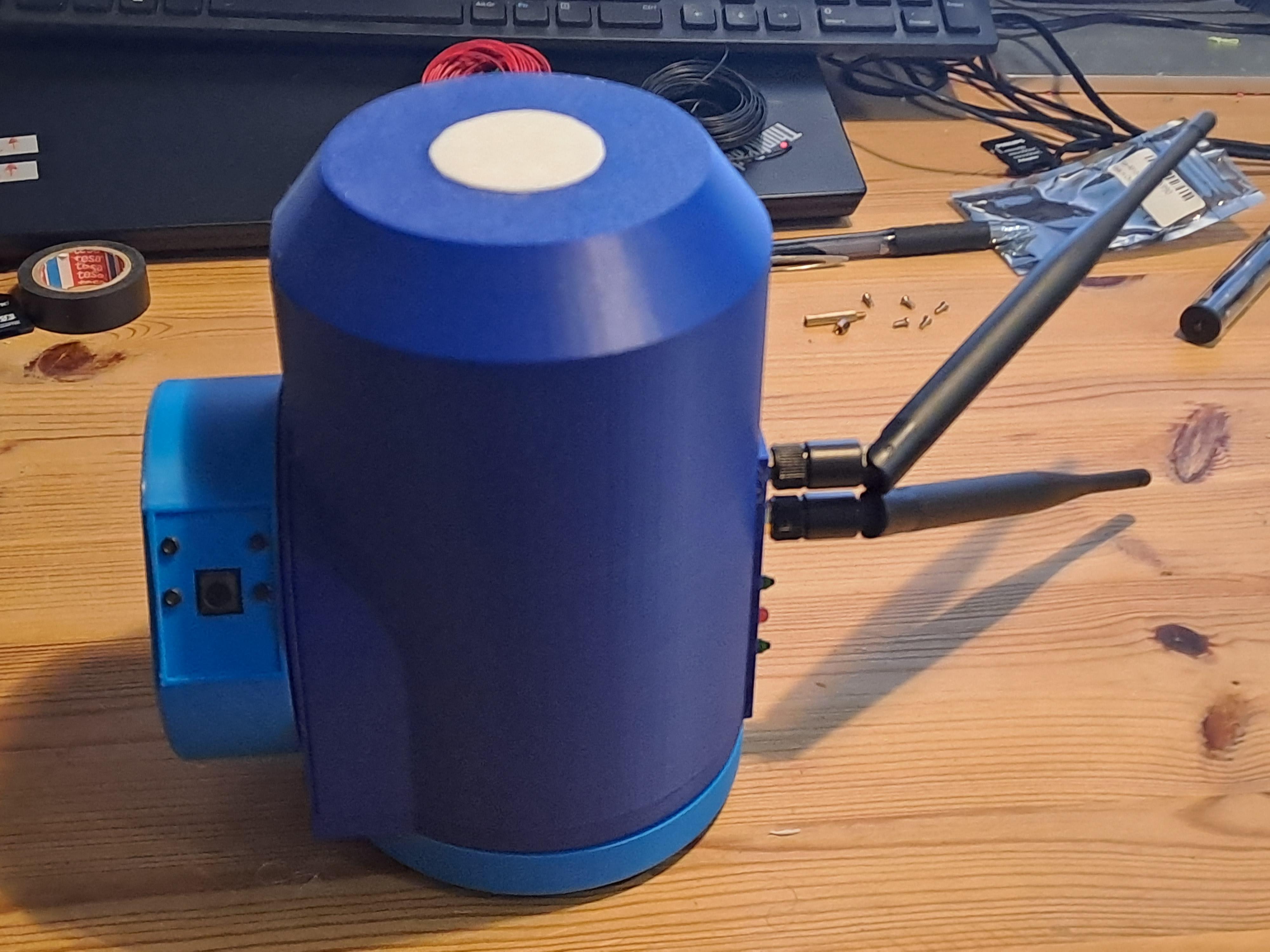
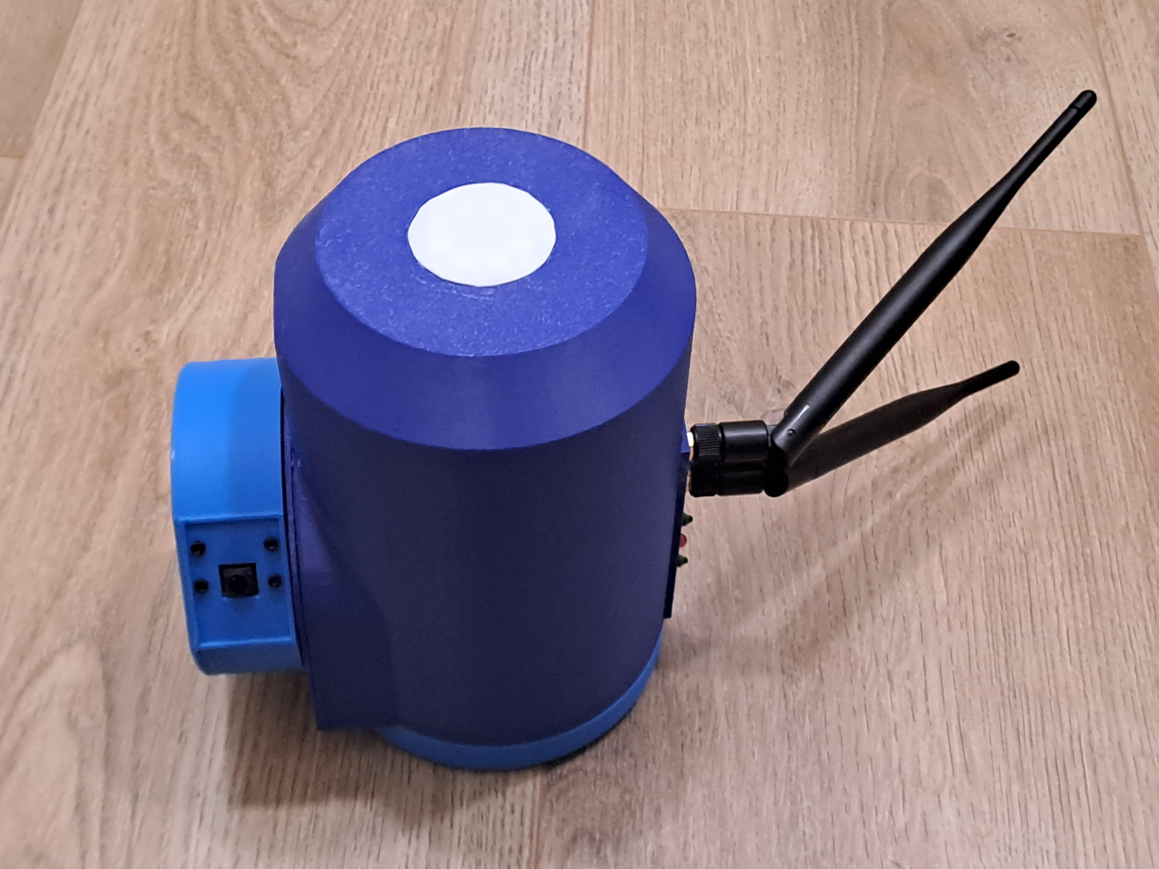
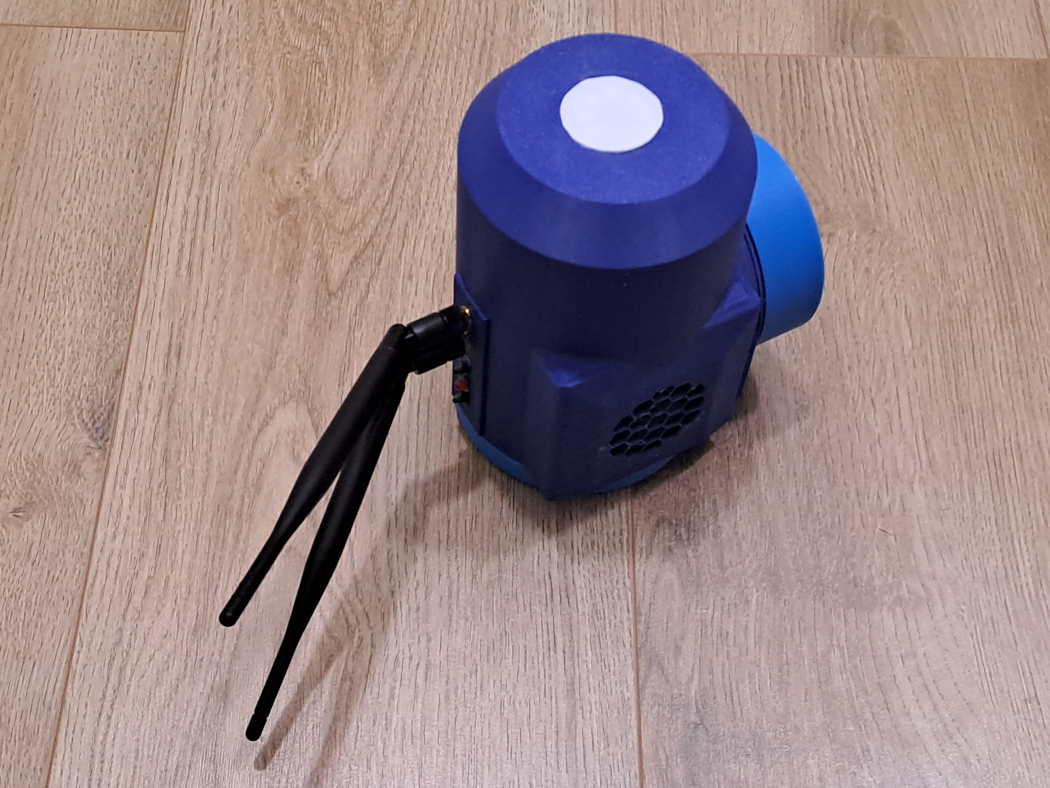
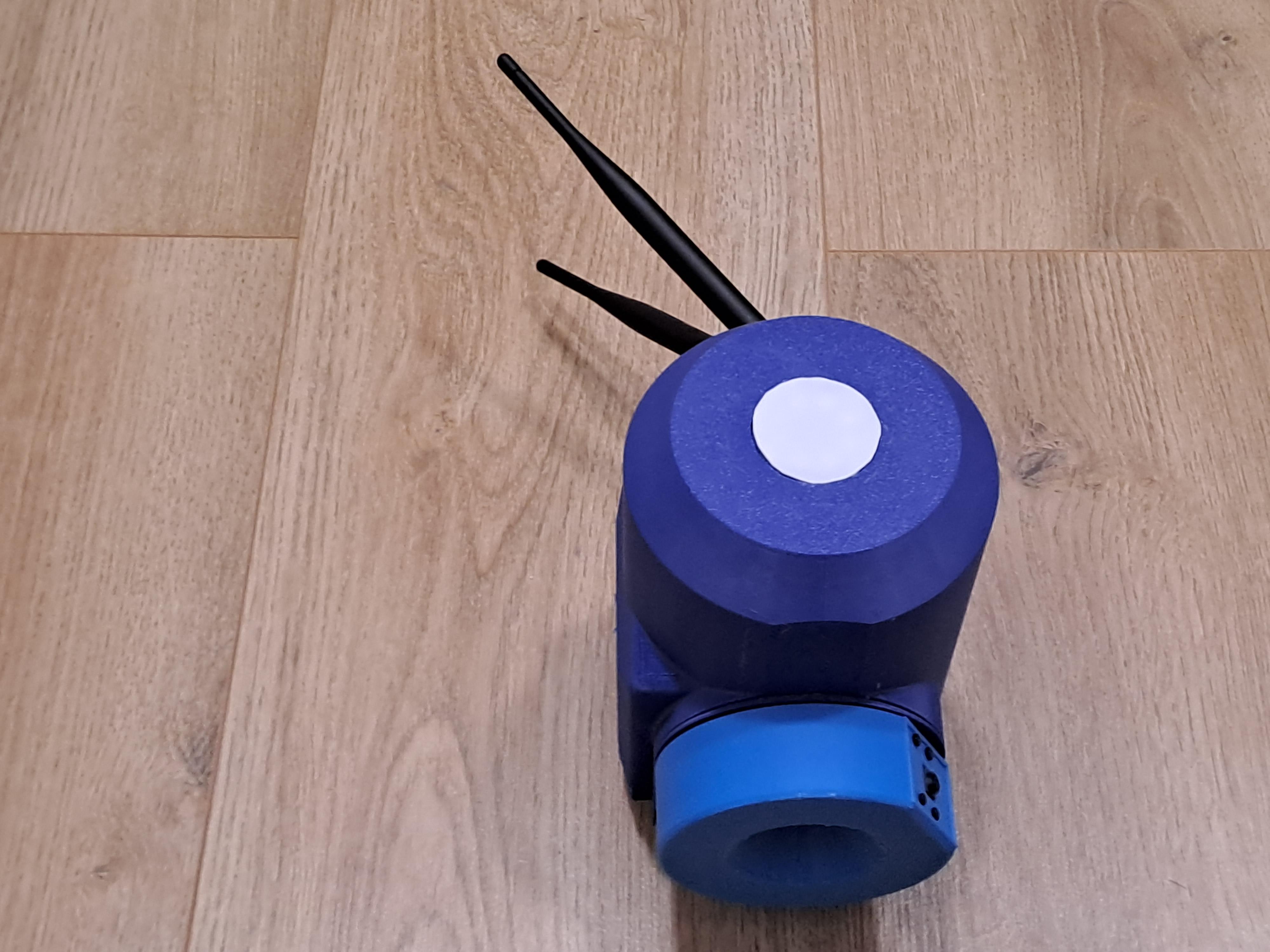
- Test all components for smooth operation.
- Move the camera wheel and servos manually to confirm there are no obstructions.
Add Scripts
Now that your hardware setup is complete, let's add the software to the Jetson Nano Linux system. For this power the camera and connect to a Computer via VNC.
Download the vt360_startup.sh script and the FLASK_APP folder from the github project.
In the FLASK_APP folder navigate to the app.py script and add your own WiFi credentials to the script:
#WIFI_SSID = 'My_WiFi_Name'
#WIFI_PASSWORD = 'My_WiFi_Password'
My recommendation is to create a WiFi hotspot on your phone and use these credentials, this will allow you to use the vt360 also outside the range of your home WiFi.
Copy both the vt360_startup.sh script and the FLASK_APP folder to your Desktop folder on the vt360 system.
Run Scripts on Startup
To automate tasks, we can use CRONTAB in Linux:
- 📋 Add to Crontab. Open a terminal and type:
- This opens the crontab. It is very annoying to navigate in crontab if you were born (like me) after 1985 and think user firendly GUIs are a human right.
If you eventually manage, add this line:
3. Save and exit typing: :wq
Test the Camera
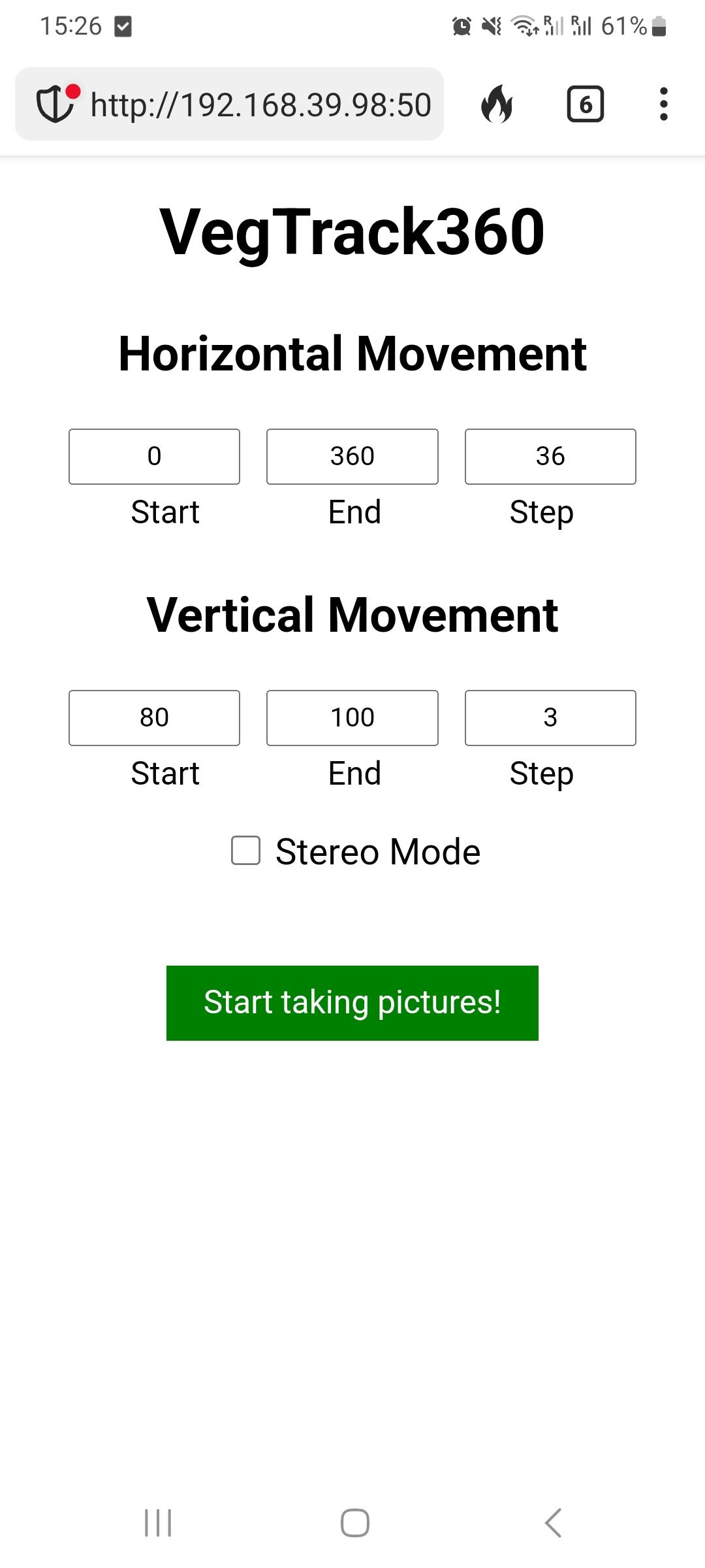
- Power on the camera.
- It should connect to your WiFi network automatically. Remember, it is best using a WiFi hotspot on your phone, but any WiFi will work.
- Use a browser to find the camera’s IP address. If you can't find it use an app like Fing to find its IP address on your network. A typical IP address could look like this: http://192.168.39.98:5000/
- A control panel should load that looks like the picture above.
- Press the green "Start Taking Pictures" button to capture your first set of images.
- Of course you can adjust the covered images per rotation and the start and point of the movements.
Build Stationary Base Plate
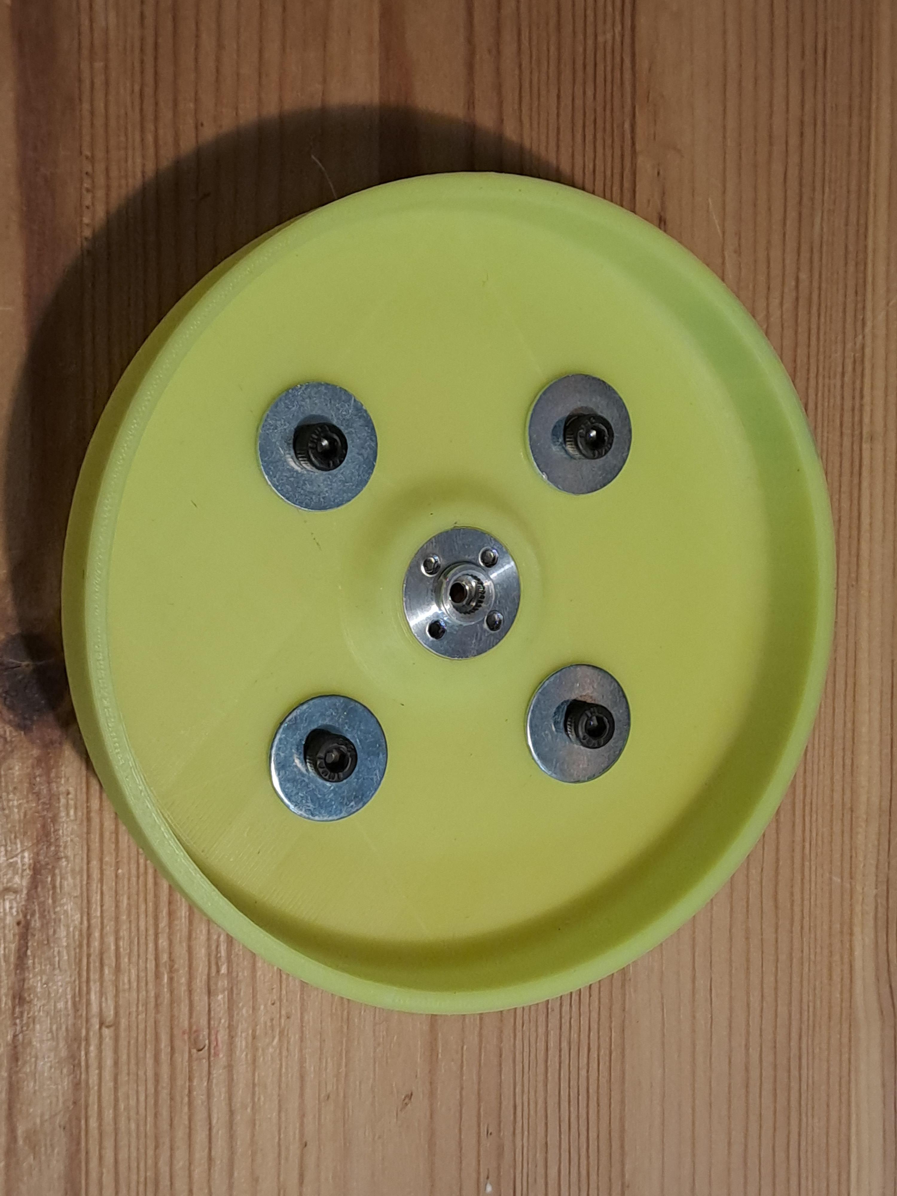
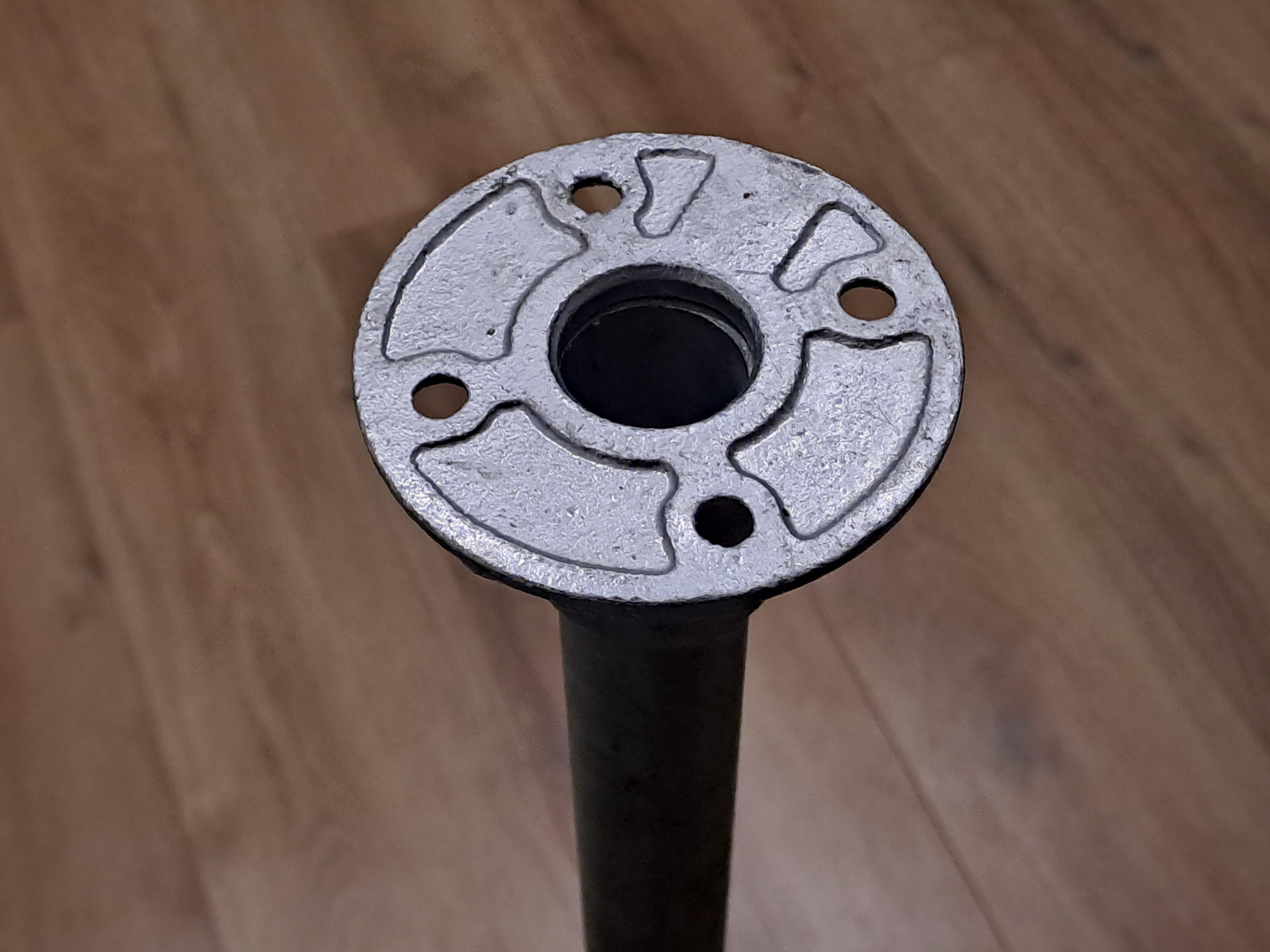
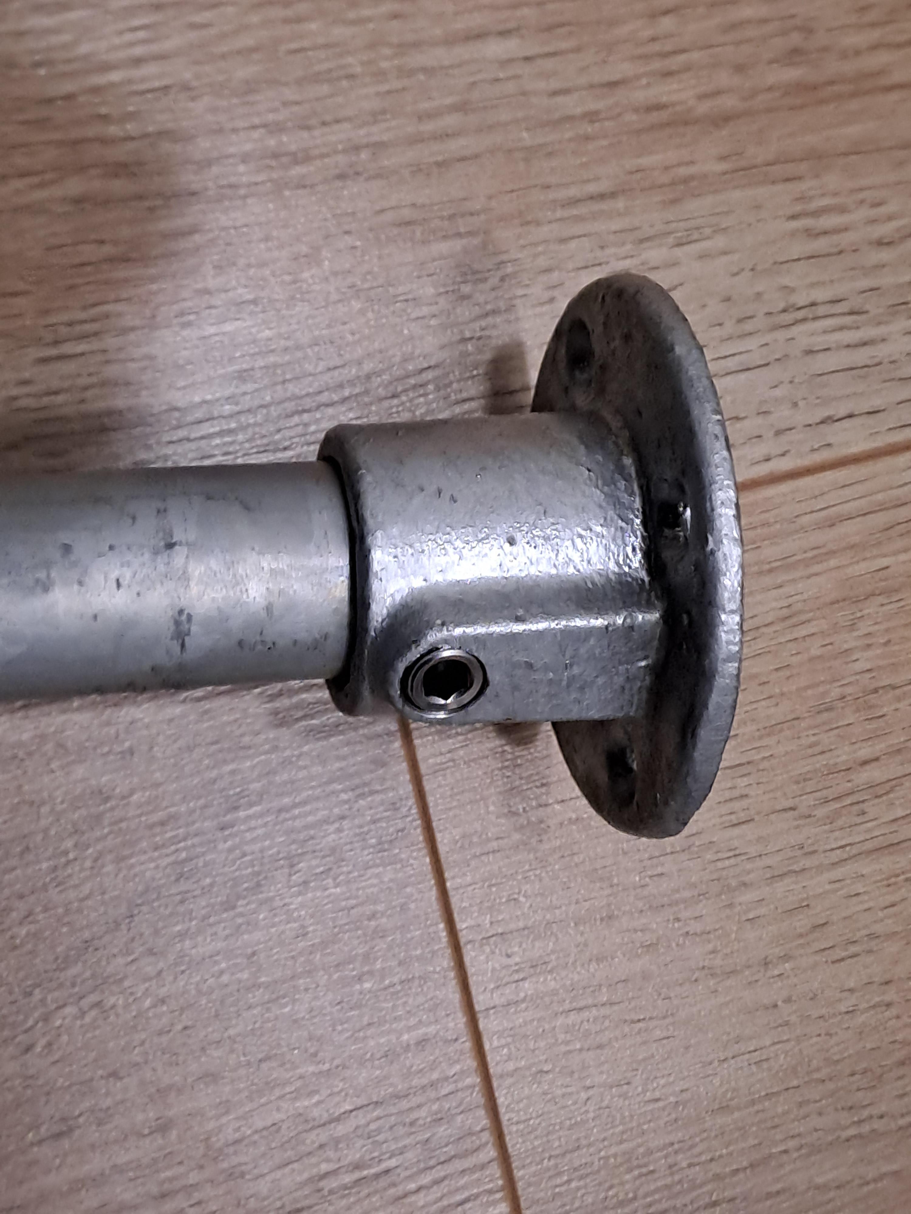
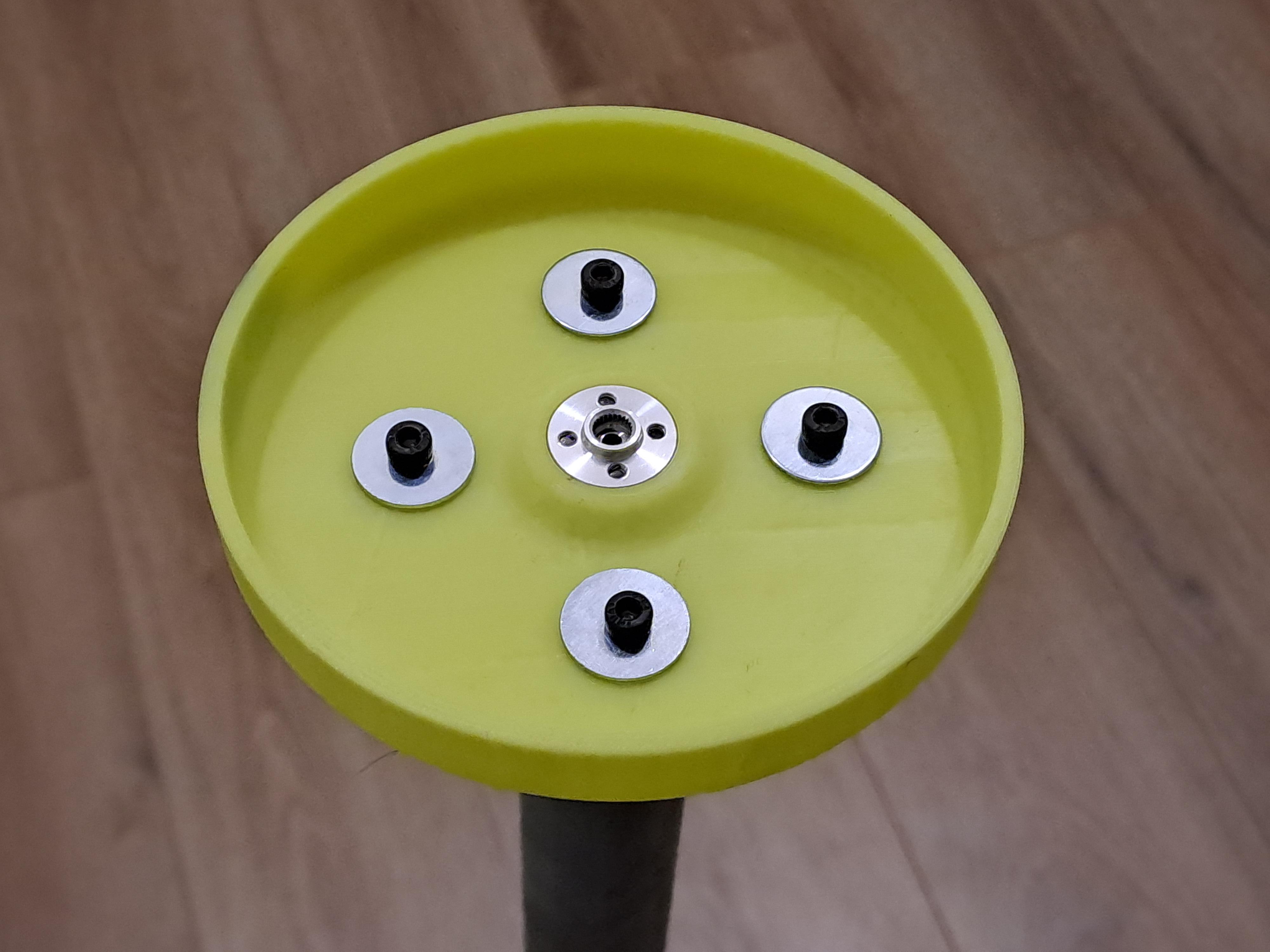
Create a sturdy base plate for stationary applications. Avoid leaving the camera outdoors permanently unless weatherproofed. Optionally you can use the tripod mount in the next step below.
Build Base Plate for Camera Tripod
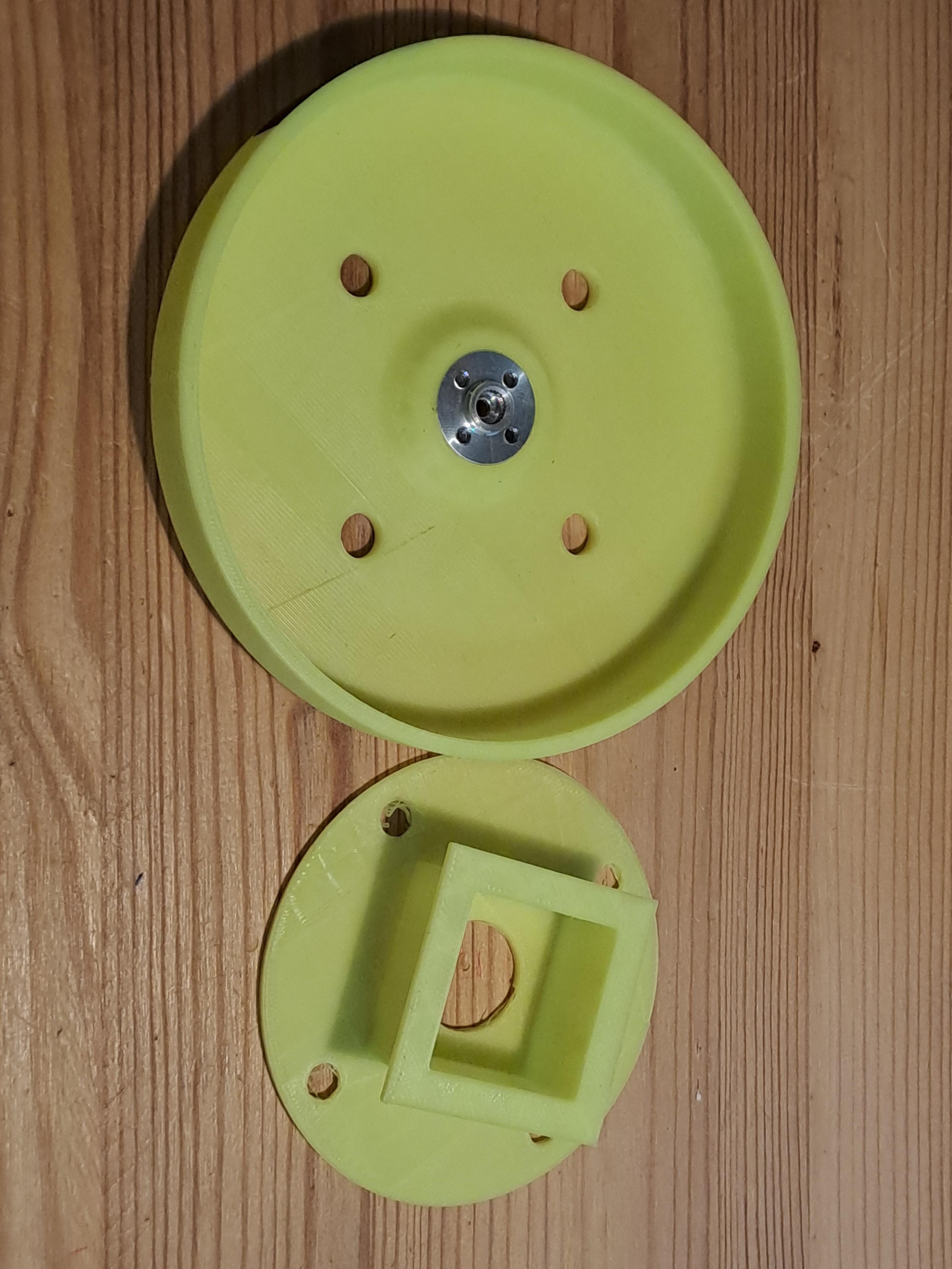
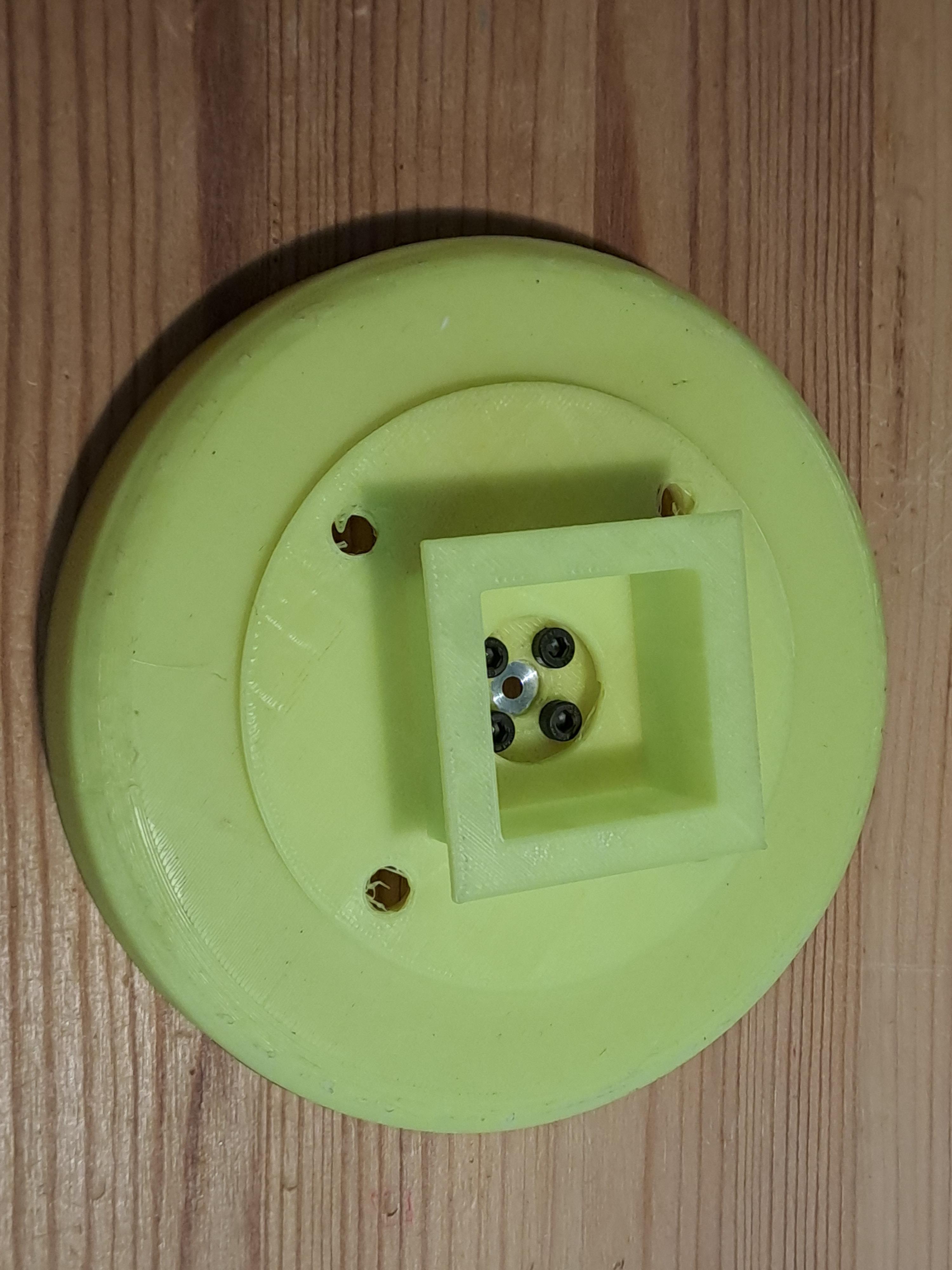
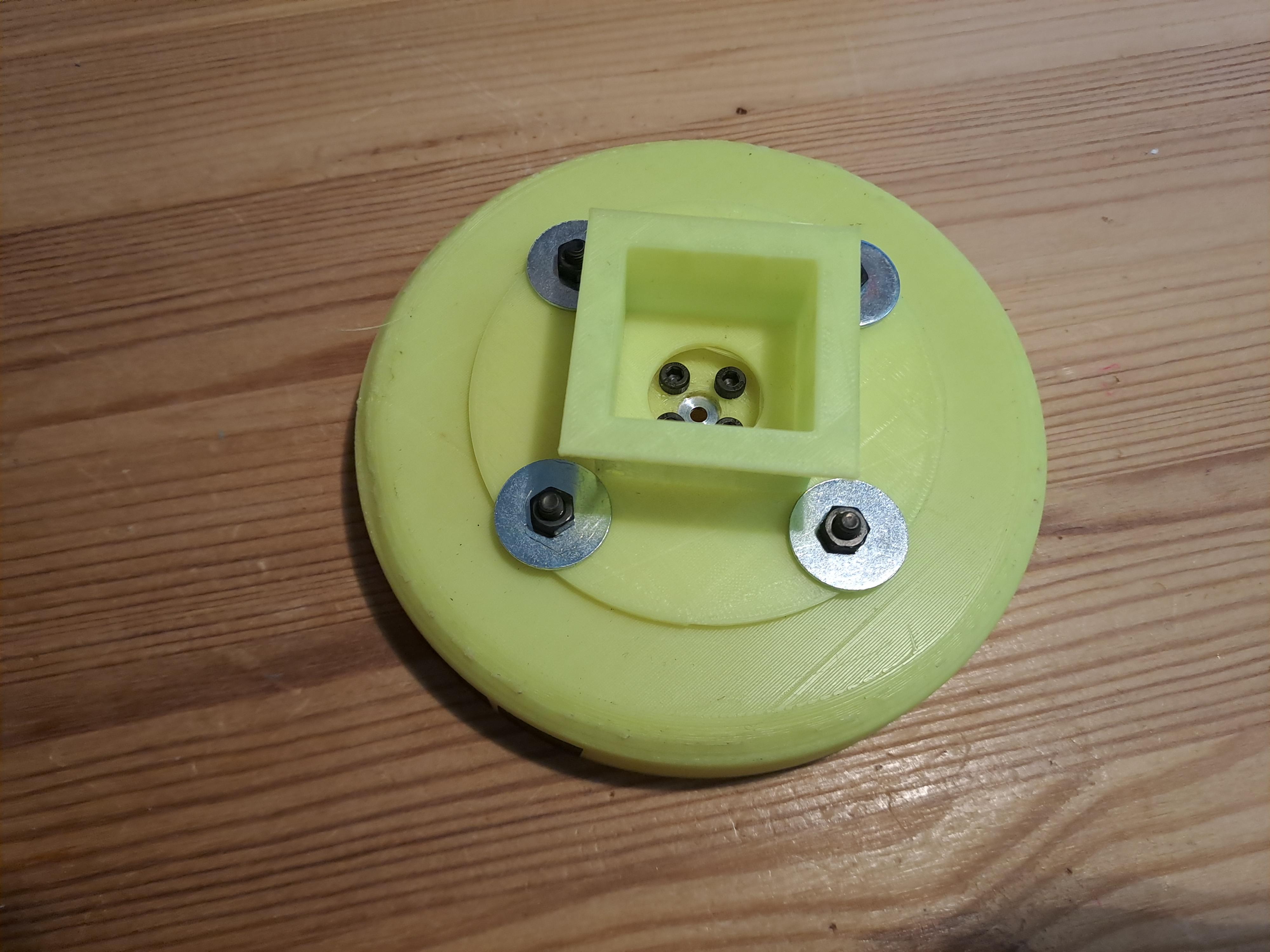
A tripod-compatible base plate is ideal for portable setups.
Thermal and Multispectral Camera Wheels
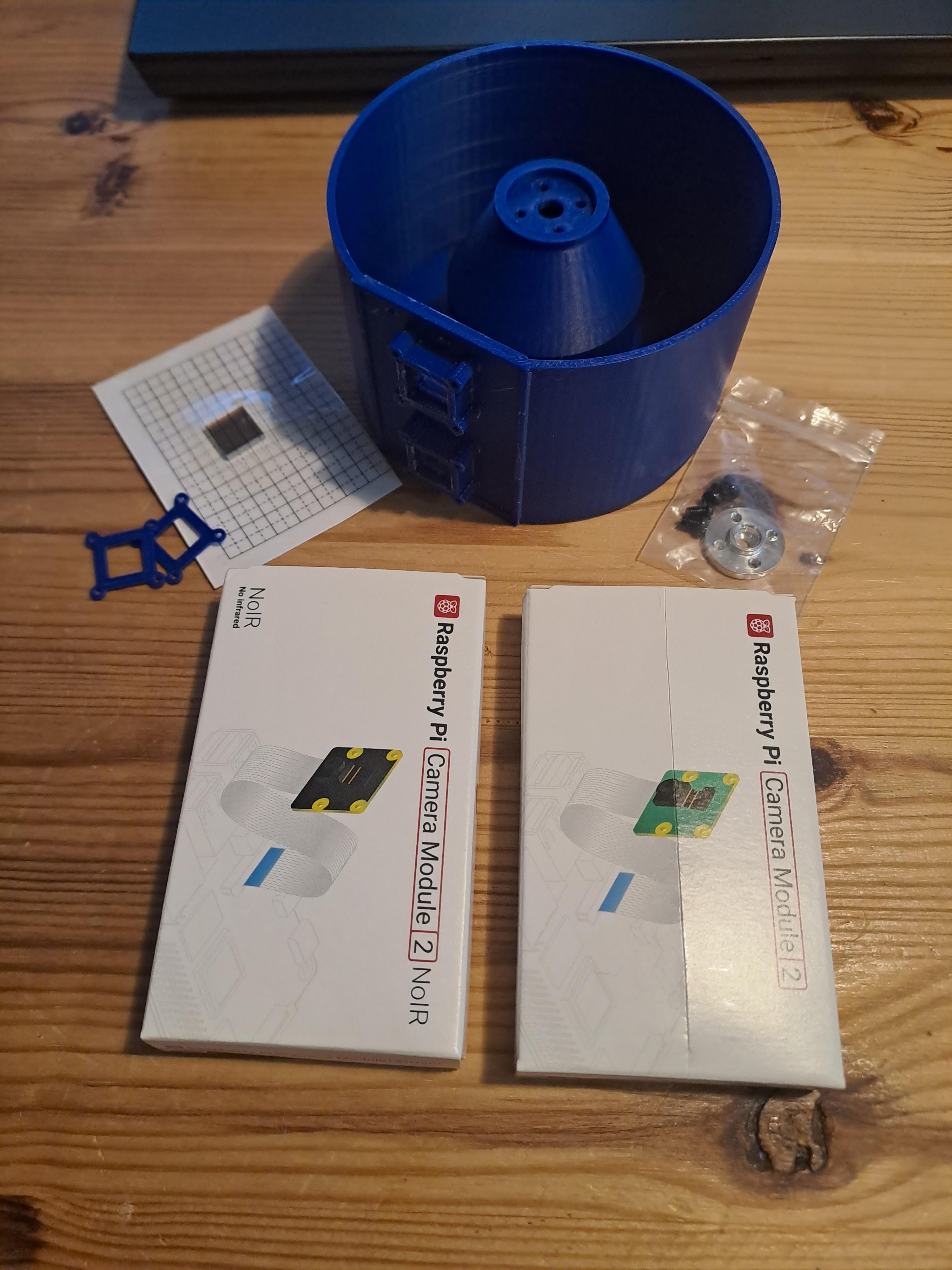
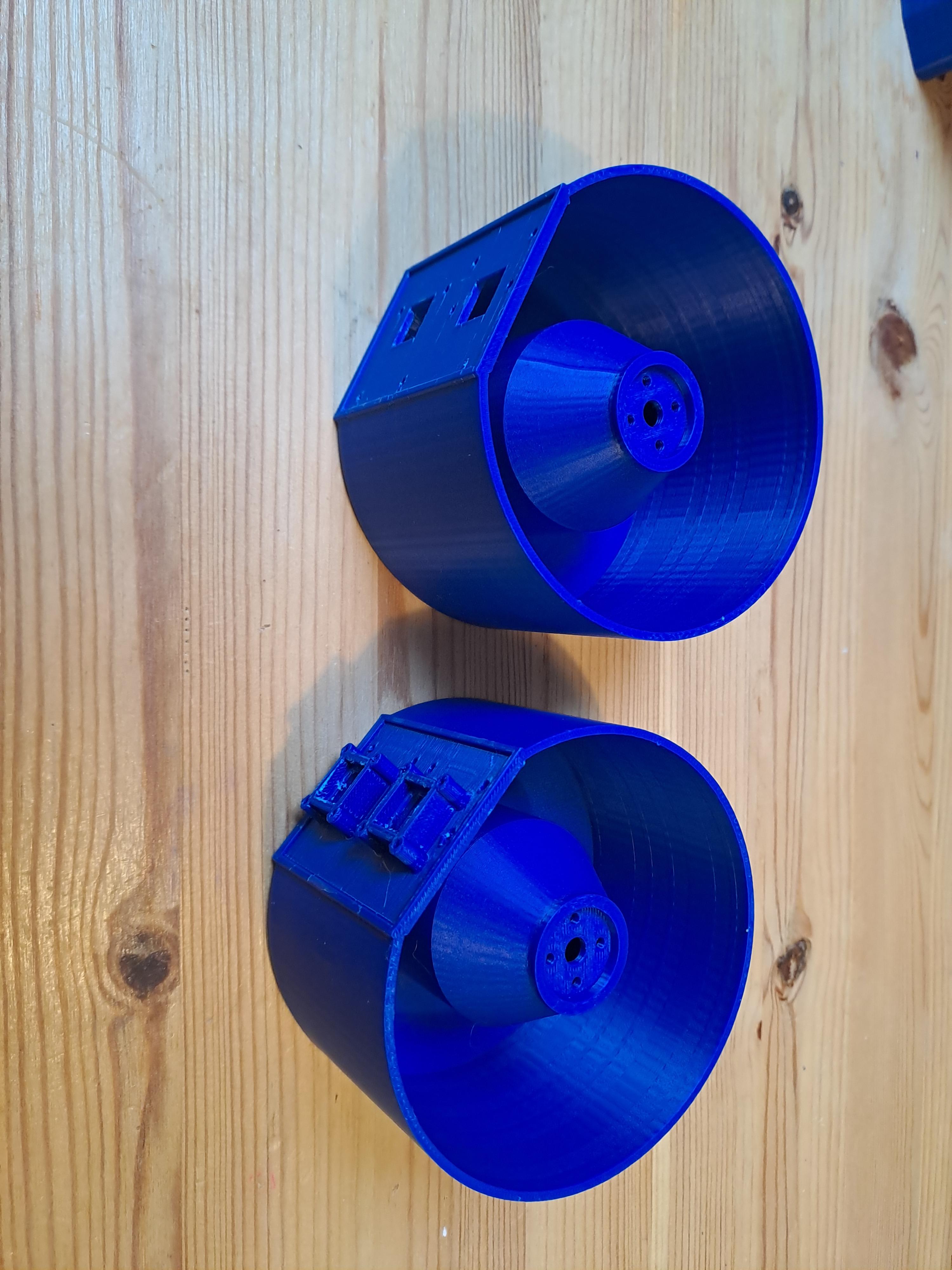
Experiment with other sensors! Add wheels for bandpass-filtered cameras or FLIR Lepton thermal sensors for advanced imaging.
Troubleshooting Tips
If you face port issues:
- Update and install tools:
- Check and kill processes on a port: