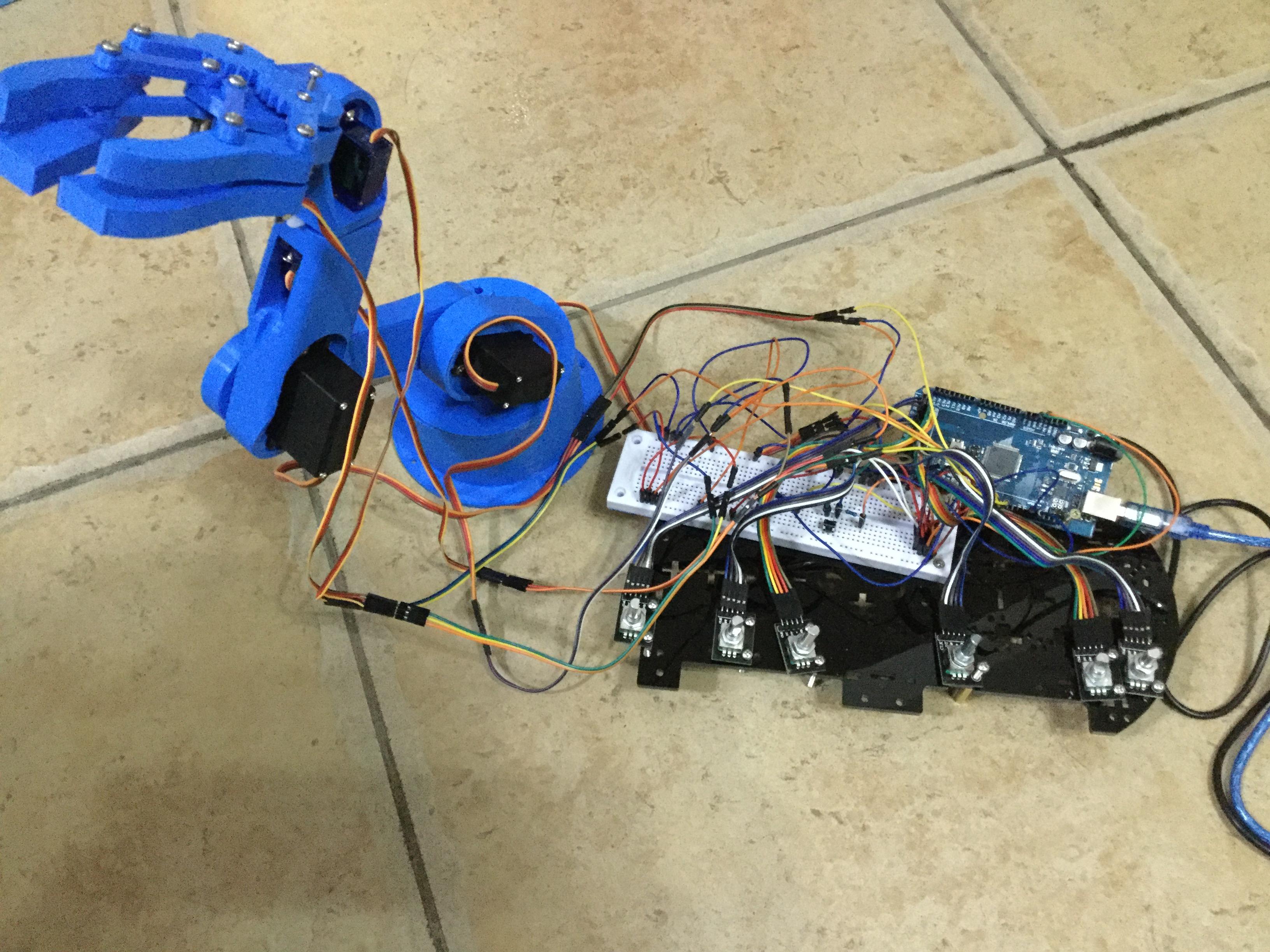
Rotary Encoder Controlled Robot Arm
by GeniusKevins in Circuits > Arduino
3455 Views, 7 Favorites, 0 Comments
Rotary Encoder Controlled Robot Arm
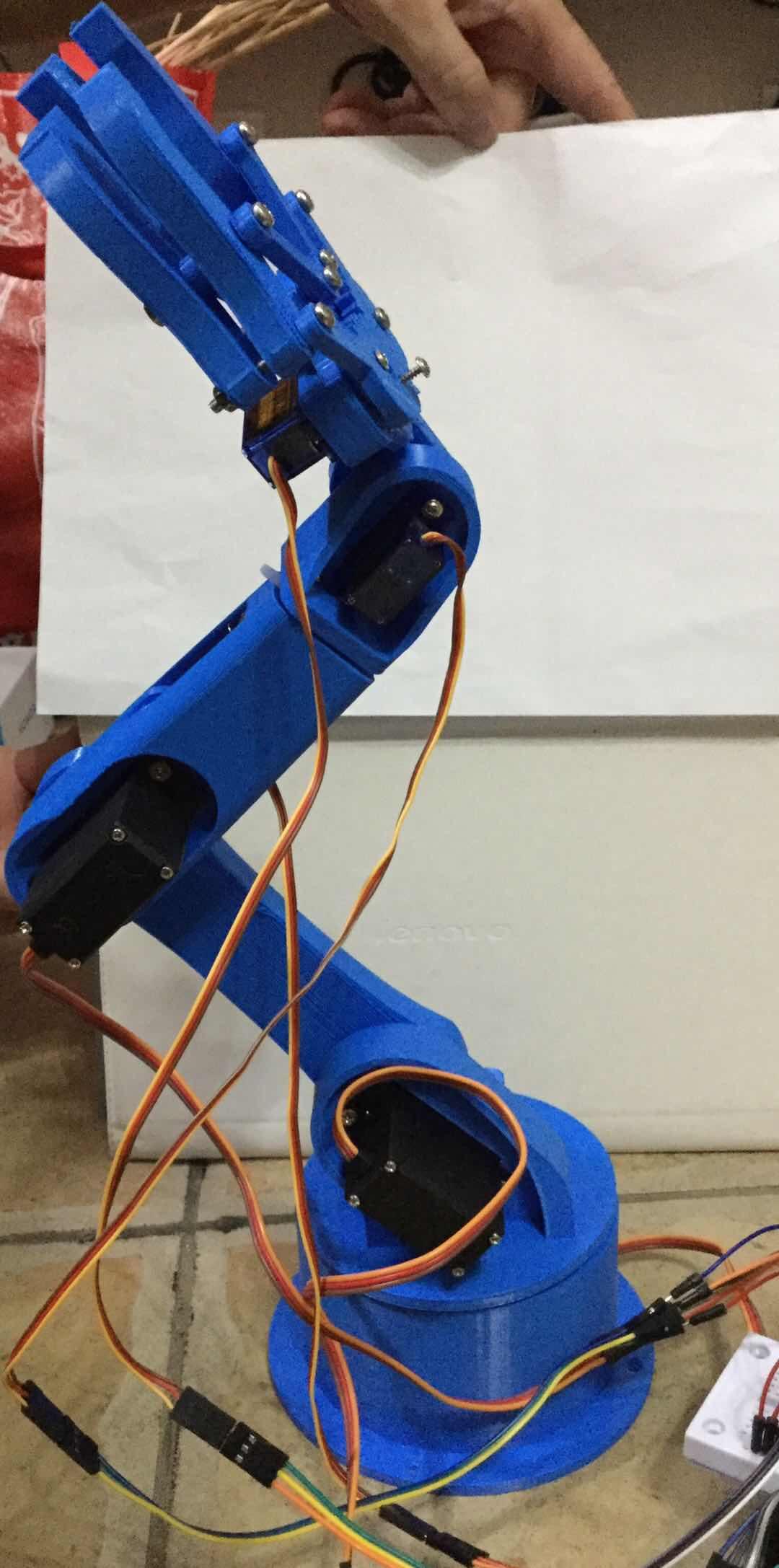
It would be nice to make a rotary encoder controlled robot arm using my 3D printing machine.
I don't like to use bluetooth, plus I saw we can control servo with rotary encoder, so I redesign it that I can control the robot arm use rotary encoder and record it
Supplies
SG90*3
MG996*3
rotary encoder*6
Arduino mega *1
2 pin push button*2
560 ohm resistor*2
M3 screws and nuts
3D printer
Connect the Servos
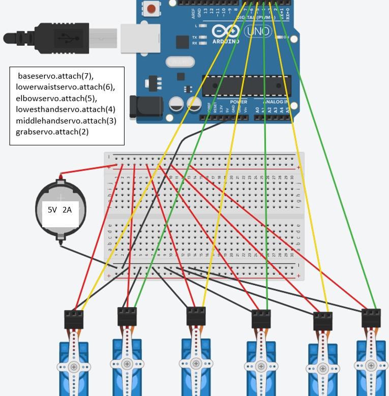
From left to right: base servo (MG996), lower waist servo (MG996), elbow servo (MG996), lowest hand servo (SG90), middle hand servo (SG90), grab servo (SG90)
We must not wire the Arduino’s 5V to external 5V (that is resistor in parallel and they will try to charge each other) But we need connect ground together as a reference so they will work If you don't have the ground connected to the Arduino, there is no return path for current from your signal wire (yellow wire), so the external power's ground should wire to both the servo ground pin and Arduino’s ground pin. (While black and red wire are independent power supply)
Note here I separated the connection diagram to servo, push button and rotary encoder because it is easier to read separately (they all connect to a single Arduino Mega using pin on each diagram)
Connect the Push Button
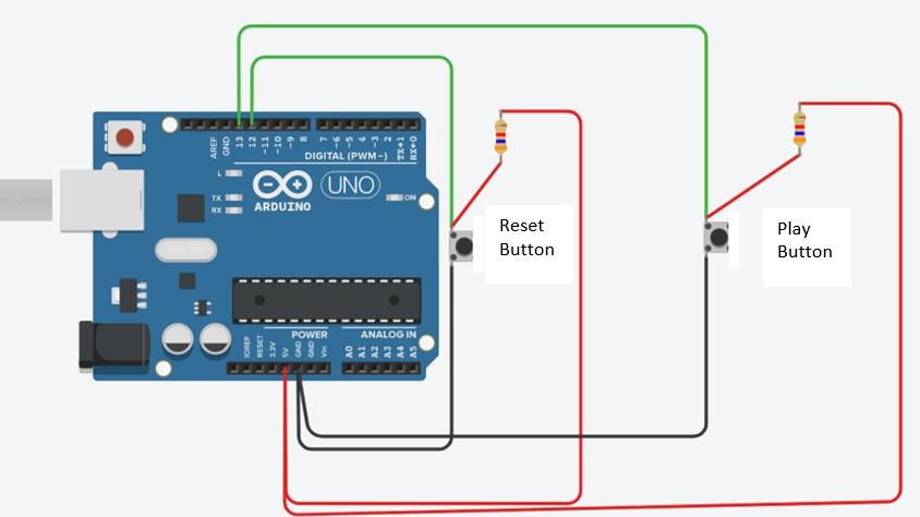
The left one is reset button
The play button is the right one
The play button will play the recorded movements
The resistor I used is two 560 ohm
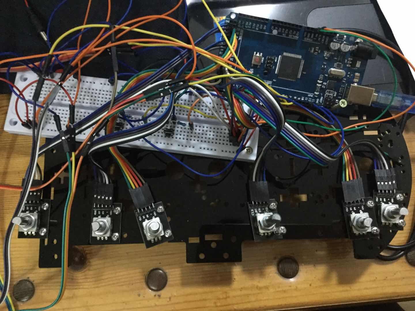
Connect the Rotary Encoders
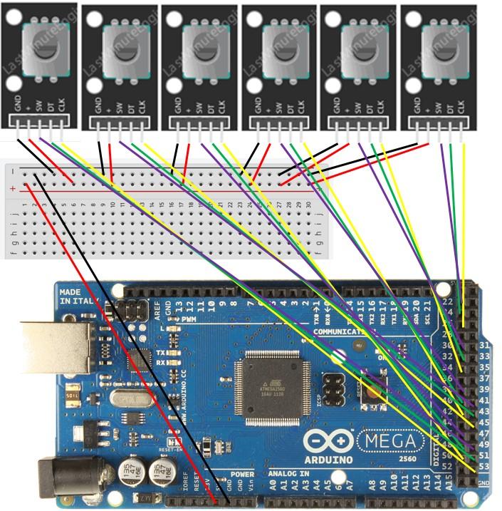
Connection pins:
// Rotary Encoder 1 Inputs
#define CLK1 53 #define DT1 51 #define SW1 49
// Rotary Encoder 2 Inputs
#define CLK2 45 #define DT2 43 #define SW2 41
// Rotary Encoder 3 Inputs
#define CLK3 50 #define DT3 48 #define SW3 46
// Rotary Encoder 4 Inputs
#define CLK4 42 #define DT4 40 #define SW4 38
// Rotary Encoder 5 Inputs
#define CLK5 34 #define DT5 32 #define SW5 30
// Rotary Encoder 6 Inputs right most
#define CLK6 26 //26 #define DT6 24 //24 #define SW6 22 //22
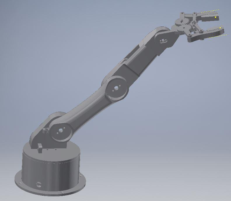
The the STL Files
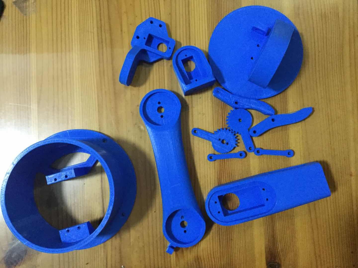
The STL files I got from online and did a bit editing.
The Code
Steps:
Press reset (reset the play)
For servo except grab servo: rotate rotary encoder of each servo--press down the encoder (record start position) for each servo like rotate encoder 1--press rotate encoder 1--rotate encoder 2--press rotate encoder 2
After we record the start positions, we can do the same to record the end position
For grab servo: (with the other servo) press down the encoder (record grab open) (after we record the start position of the other servo and they are at that position) rotate--press again (record grab close to catch something) (after we record the end position of the other servo and they are at that position) rotate-- press down the encoder (record grab open to release object)
press start button (the servos will rotate begin at start position, to end position) //if want repeat the process, need press start button multiple times
the play button is the right one
Downloads
Assembly
