Roof Tile Texture Roller (Works for Any Texture)
by ShrimpHeavenNow in Workshop > 3D Printing
1401 Views, 16 Favorites, 0 Comments
Roof Tile Texture Roller (Works for Any Texture)
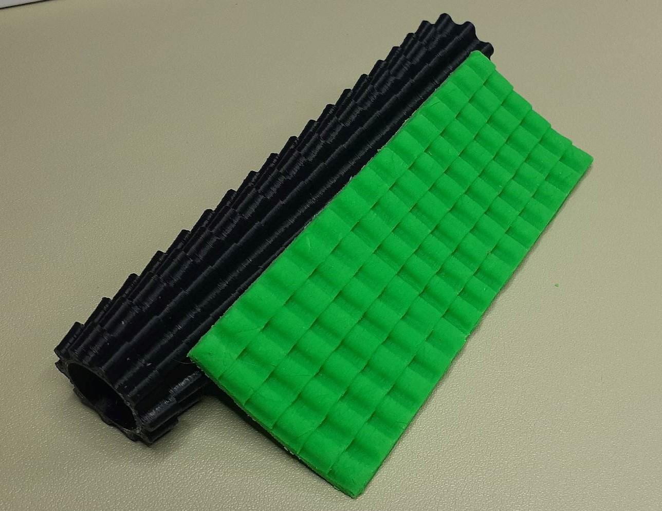
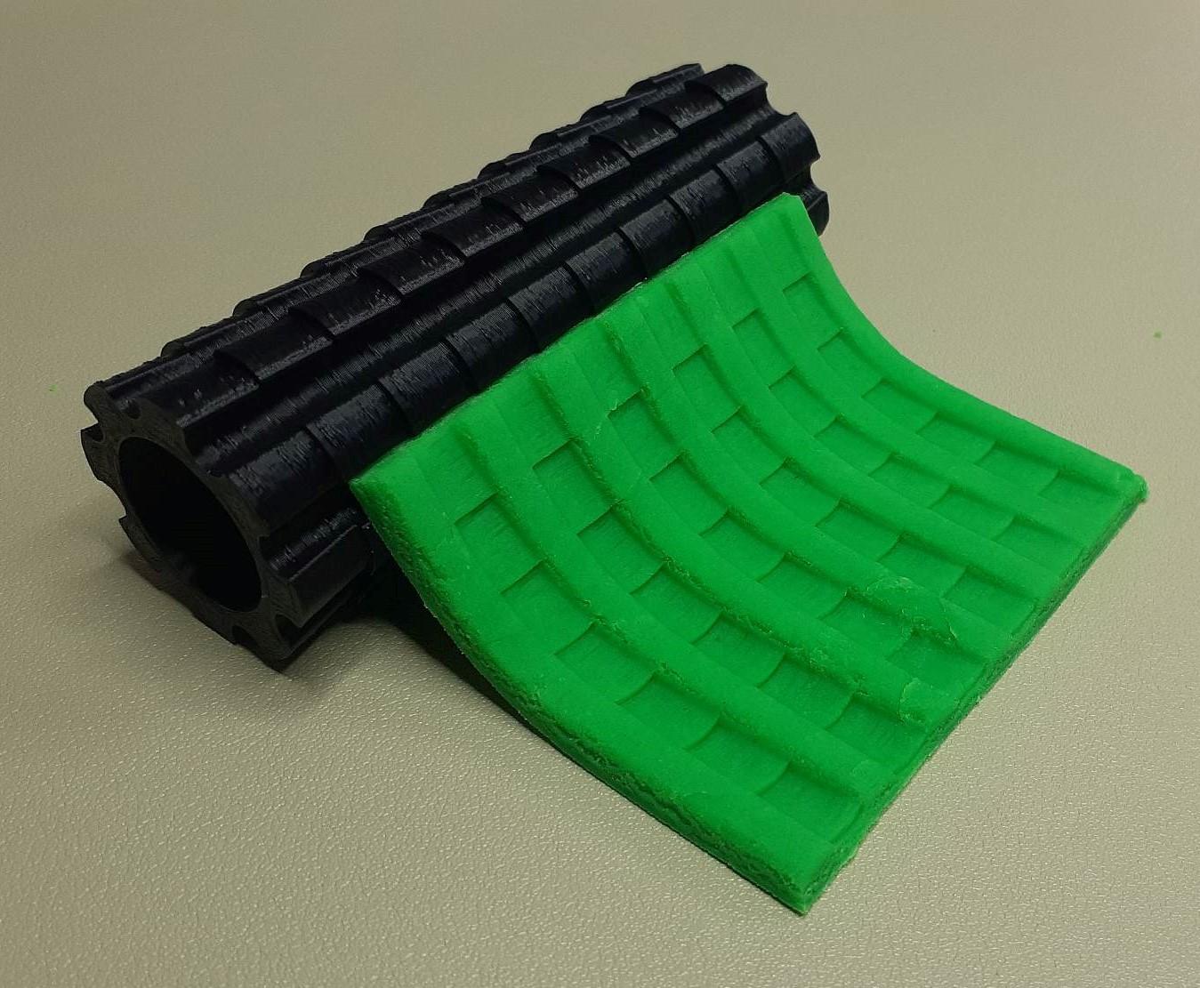
Recently I decided I wanted to make a model house of a Spanish colonial style building I saw on a trip but didn't want to make each shingle/roof tile individually so I came up with this technique to make texture rollers! Using this technique I was able to make one for a Japanese Hongawara Buki Style roof as well.
While these instructions are tailored to making roof tile texture rollers, you can follow essentially the same procedure to make any kind of texture roller!
The finished product STLs ready for printing can be found here:
Spanish Colonial: https://www.thingiverse.com/thing:5890793
Japanese HongawaraBuki: https://www.thingiverse.com/thing:5890803
Supplies
For this project, you'll need:
Fusion360
Reference text/images of the roof
A 3D printer, or access to one of many 3D printing services, even check with your local library!
Clay, foam or other medium
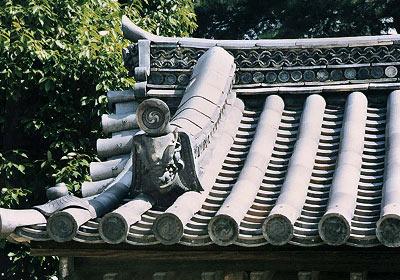
Find a Good Reference
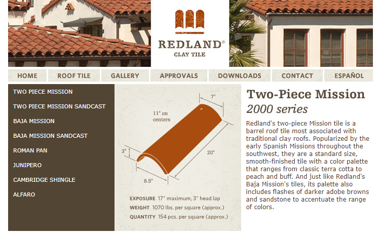
The first step is to find information. Granted our replica roller doesn't have to be exact, finding a good reference will save you a lot of time later on in Fusion360 when it comes to dimensioning and placement. If you get lucky/smart with the search terms, you might even find specifications for the exact kind of tiles you're looking for, or at least similar.
I found a website for what appears to be a roof tile supplier (www.redlandclaytile.com) specializing in tiles similar to what I was looking for with the Spanish Colonial style, which was a huge help.
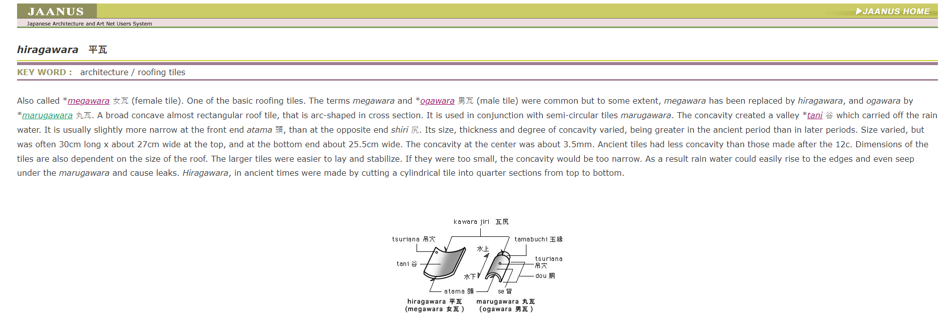
You might not be lucky as to find exact dimensions, but you might find a diagram showing how the tiles are laid on top of each other, like I found for the Japanese tiles. (https://www.aisf.or.jp/~jaanus/deta/h/hiragawara.htm)
Design a Single Top and Bottom Tile From Your Reference Into Fusion360
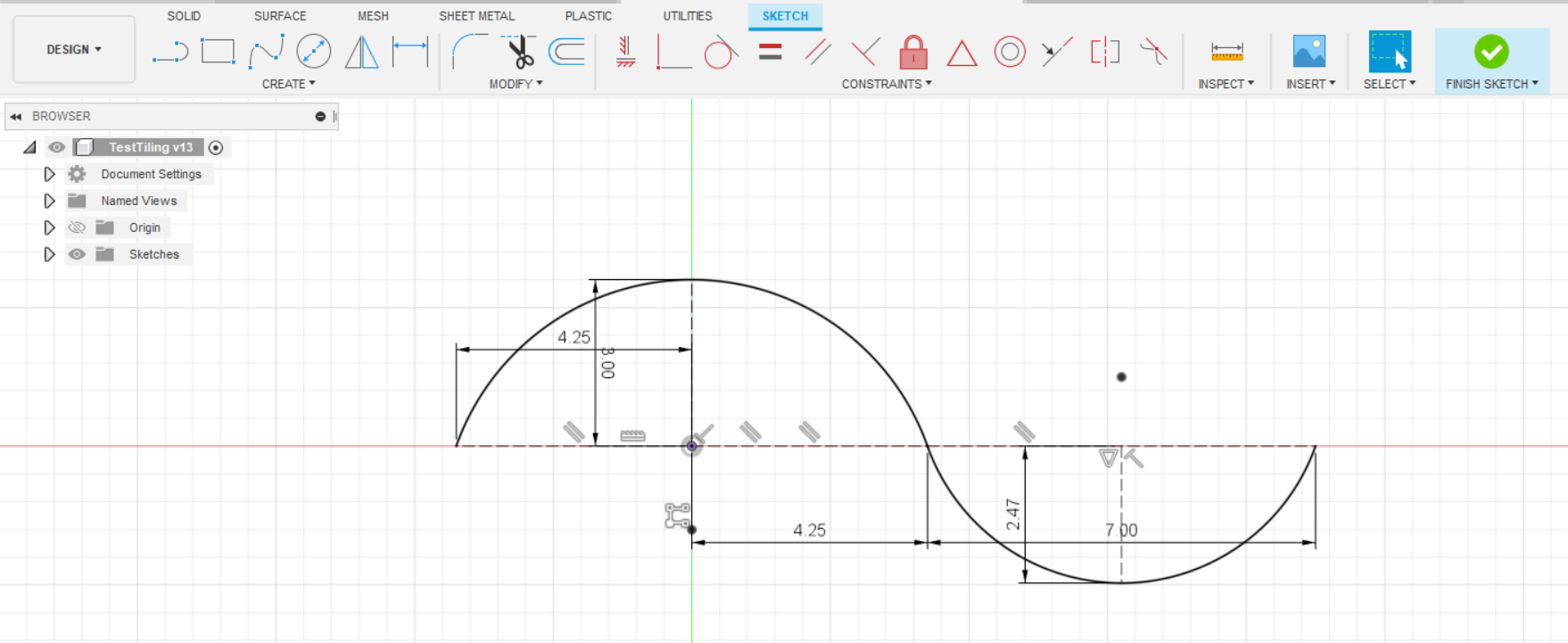
With the Spanish Colonial style, I found a couple sources saying that the top and bottom tiles are the same, just flipped over and rotated. So I took my dimensions from the reference and made an S-curve, giving us the profile of one top tile and one bottom tile.
If you do find exact dimensions, don't feel like you need to follow them exactly. We're building a little model, not a structure people will live in, So feel free to mess around until you get what looks good to you.
Keen eyes will have noticed that the reference image of the Japanese tiles, in the previous step, has two shapes, we'll come back to this in a bit. For now, let's say we only have one tile shape.
Duplicate the Sketch to Create Your First Row
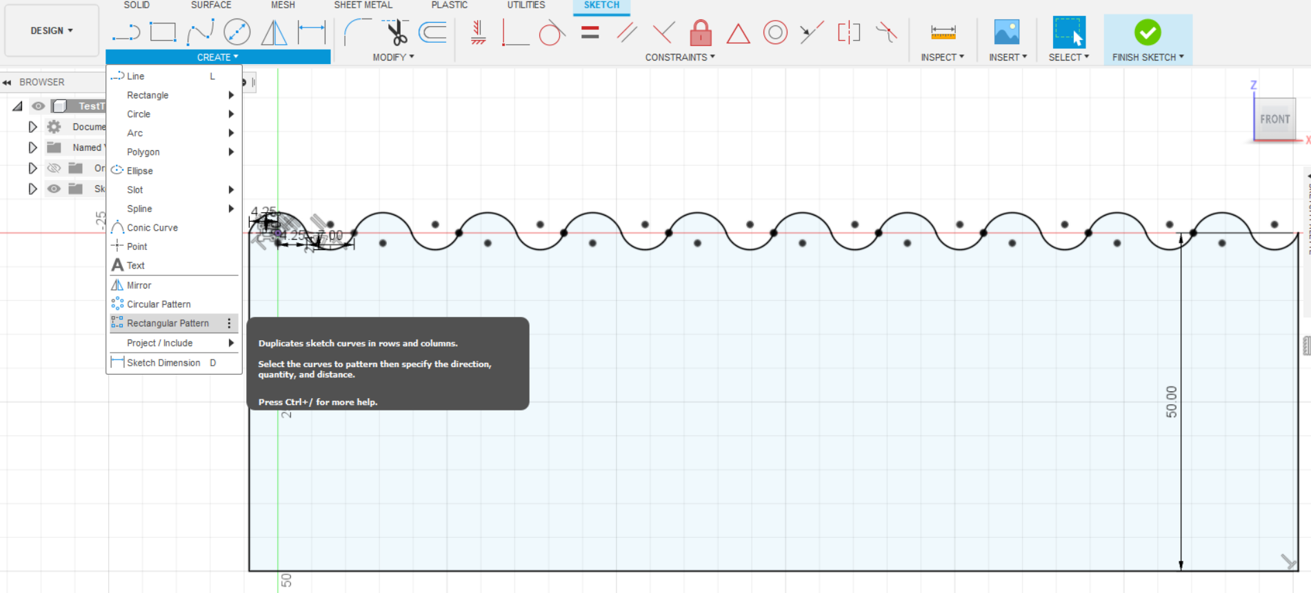
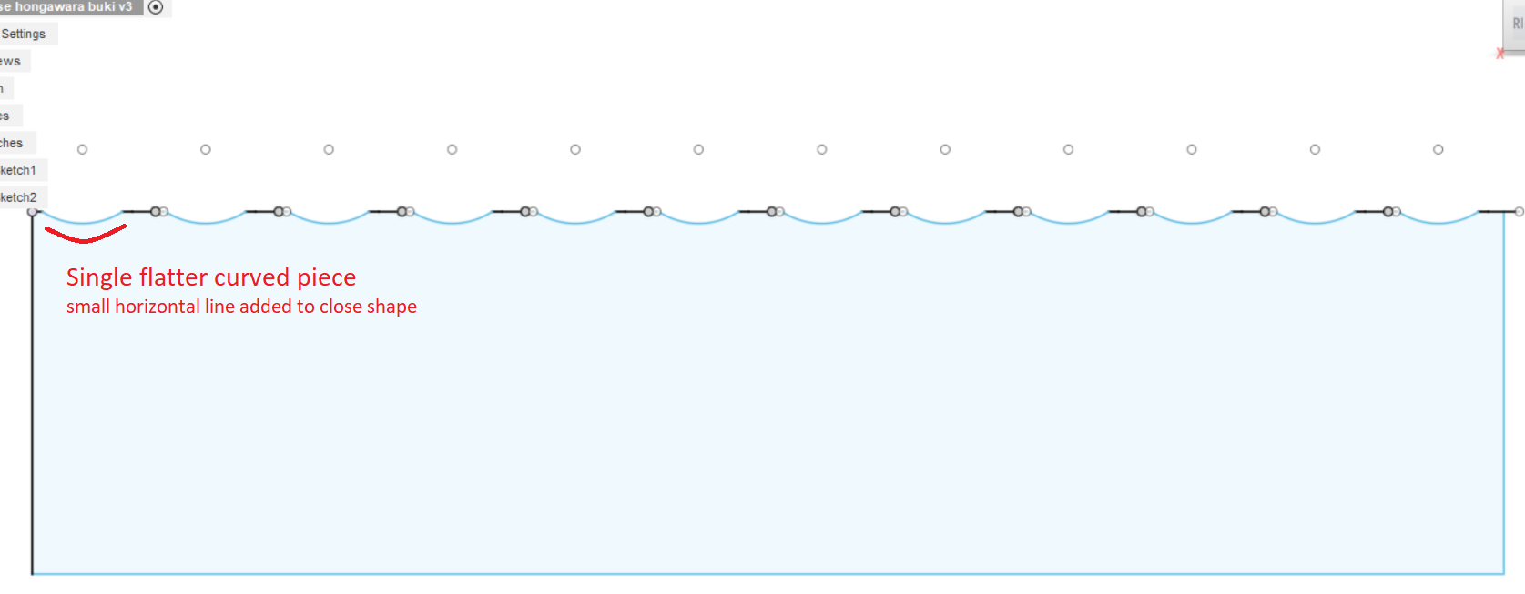
Now that we have a top and bottom tile, we'll use the Rectangular Pattern tool to make a whole bunch more to create our first row of tiles. I repeated the pattern 10 times, playing with the spacing so that all of the start and stop points connected.
After that, we draw a line straight down on each end of our squiggly line and connected them to create a sort of rectangle with a wavy top. If the created shape is closed and ready for extruding, the interior of our funny rectangle will turn a light blue.
Extrude and Angle Our First Row of Tiles
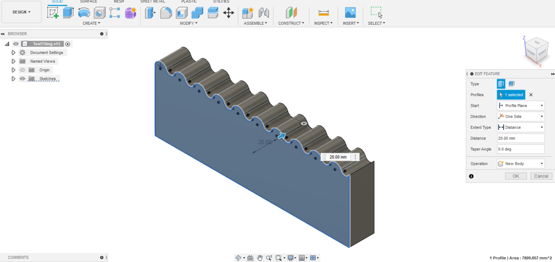
We'll now use the Extrude tool to turn our funny rectangle into a wavy brick. I extruded my shape 20mm because I liked the way it looked, but you should play around to find what looks best to you. The good thing about Fusion360 is that we can keep working and come back to any step and make changes that will automatically update.
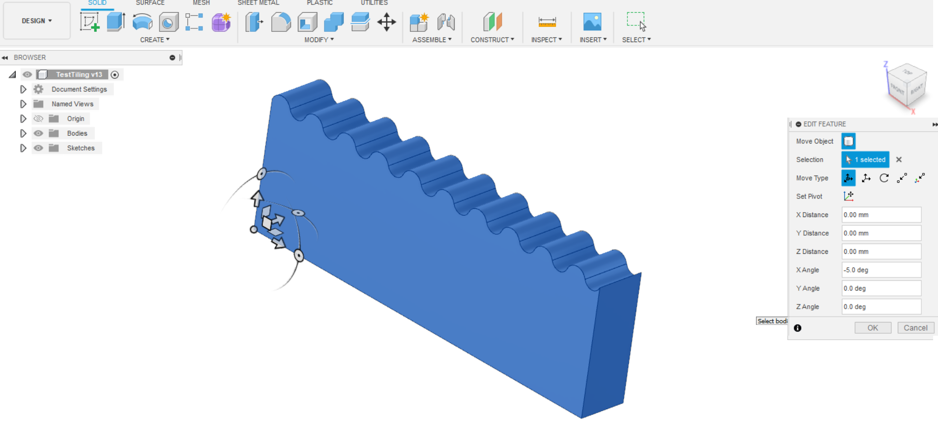
We'll also go ahead and use the Move/Copy tool and add a little angle on the bricks, so when we add the next row, it looks like the tiles are stacked on top of each other. I angled my brick 5°, again because I thought it looked about right.
If your tiles only come in a single shape, like the Spanish tiles, skip ahead to Step 7. For the Japanese tiles, our tiles come in two shapes, a semi-circle and a flatter curved piece so we'll need an extra few steps.
If Your Tiles Come in More Than 1 Shape (Sketch)
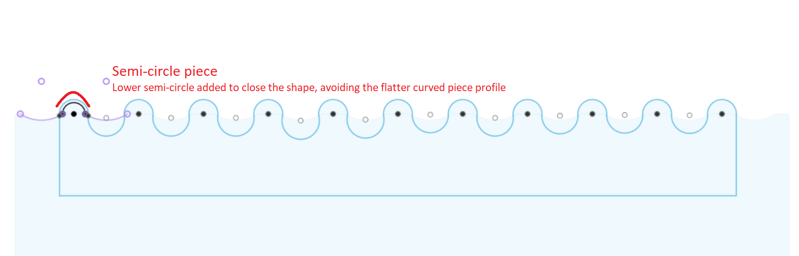
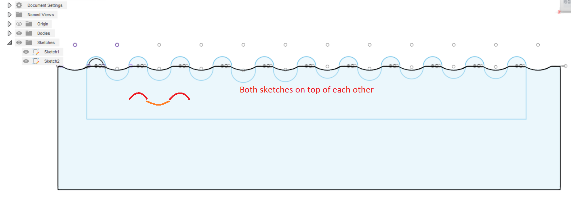
As mentioned, the Japanese tiles come in two shapes, so we'll just do everything from steps 2-4 twice! Once for each shape. First the flatter curved piece was sketched and patterned, playing with the spacing and then making our rectangle. Next the semi-circles were drawn in their own sketch following the same principles.
Once you have both sketches, it should look something like the attached photos.
If Your Tiles Come in More Than 1 Shape (Extrude and Angle)
Once again, we'll use the Extrude tool to turn our two funny rectangles into two wavy bricks (keep them as separate bodies for now). I extruded these shapes 15mm this time.
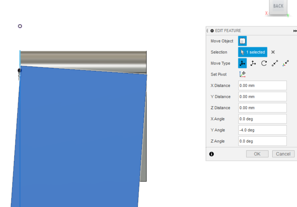
Looking at a picture of Japanese Hongawara Buki, the semi-circle part looks smooth/continuous down the roof and the flatter curve is the one that looks stepped, so we'll only angle the flatter curved piece, by about 4° and move it around so the edges still line up with the semi-circle piece.
After all of that work, we can go ahead and use the Combine tool under the MODIFY menu to turn our two pieces into a single piece!
Move/Copy Our First Row to Create Additional Rows
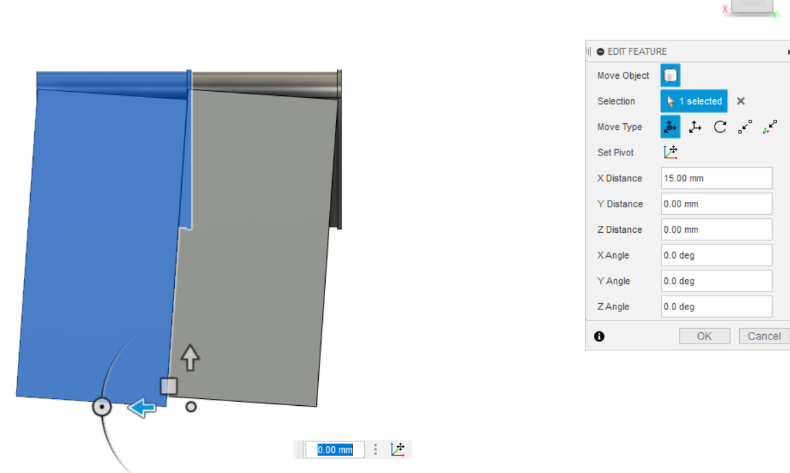
With our first row created, it's relatively smooth sailing from here. We'll use the Move/Copy tool to move and copy our first row to make a second row.
Note: You should only have to move the shape backwards or forwards, not up and down. Only moving in the X-Axis in my case. Because we angled our parts previously, we don't need to worry about any offsets.
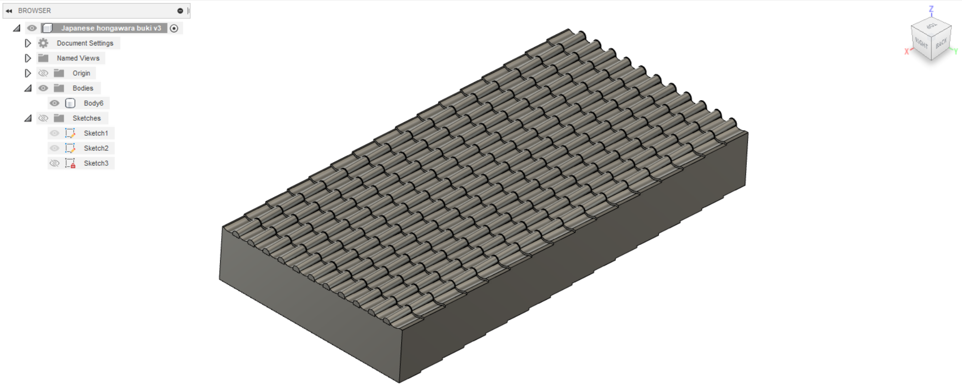
We'll repeat this to get as many rows as we think is necessary. It's better to do more rather than less to make the future steps easier.
Note 2: The pictures in this and the following steps will be of the Japanese Roof Tile Rollers but the steps would be the same for any texture
Make sure to save your work!
Using the Sheet Metal Tool Menu in Fusion360
I had never used this tool and outside of this limited application, it still seems daunting but we'll only need a few things from here.
First we need to open a new sketch (Fusion360 sometimes throws a fit when dealing with solids and sheet metal components in the same file, so I just opened a new blank file for this part)
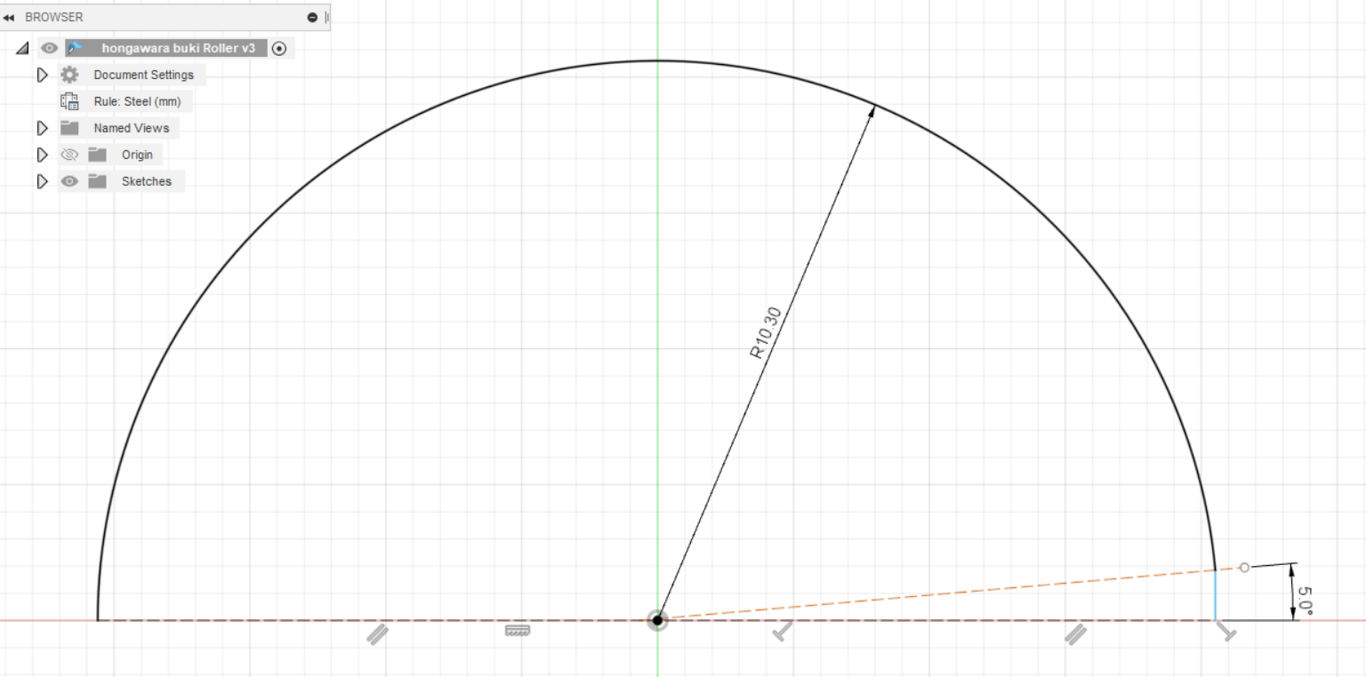
On this sketch, we need to draw a semi-circle, this will determine the internal size of our texture roller.
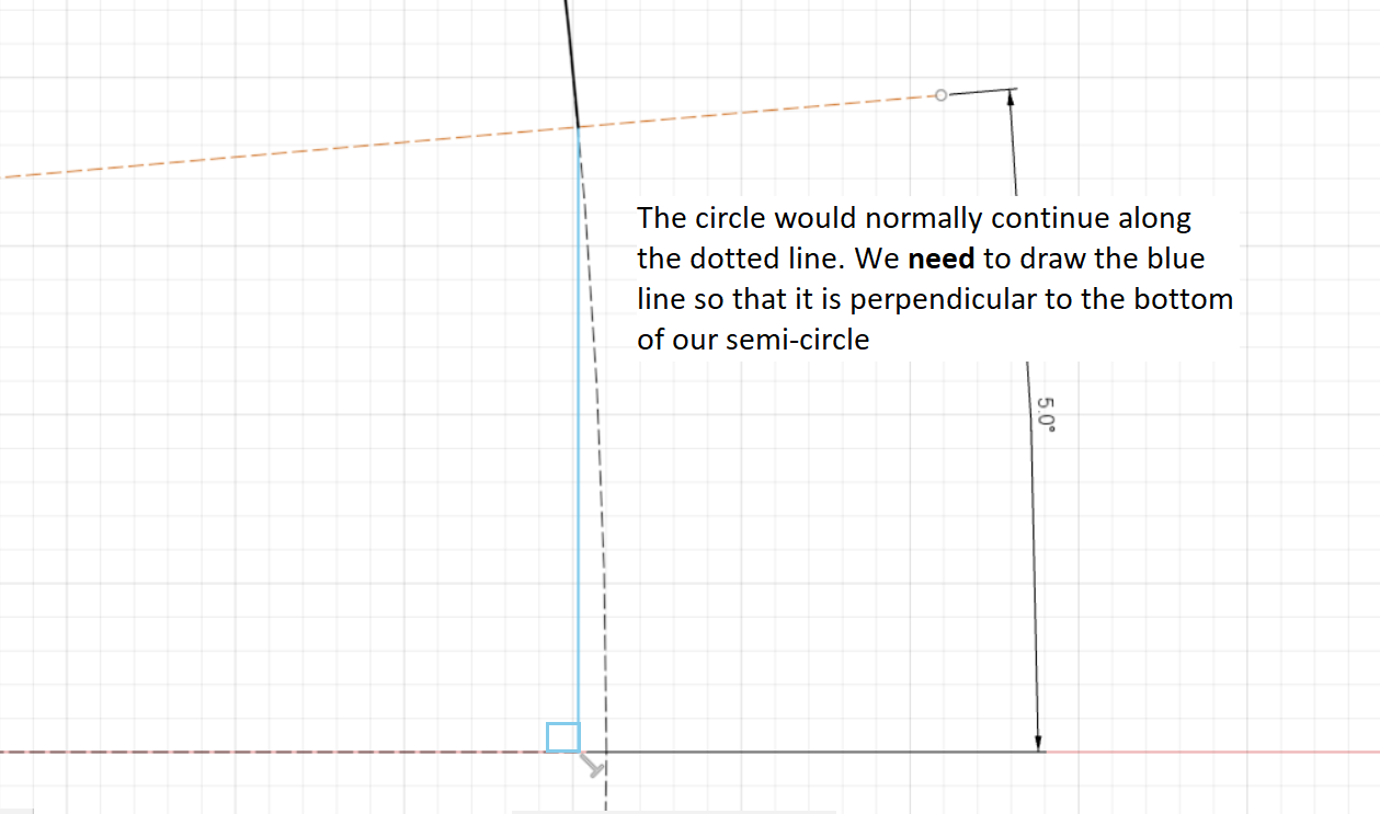
Note: This part is super important, you'll want to draw a construction line from the center of the circle to just past the circle on one of the ends of the semi-circle, about 5° is usually enough. From this construction line, we'll draw a line straight down to the flat of the semi-circle. It's crucial that this line is perpendicular to the flat.
Then we trim the excess.
Using the Flange Tool
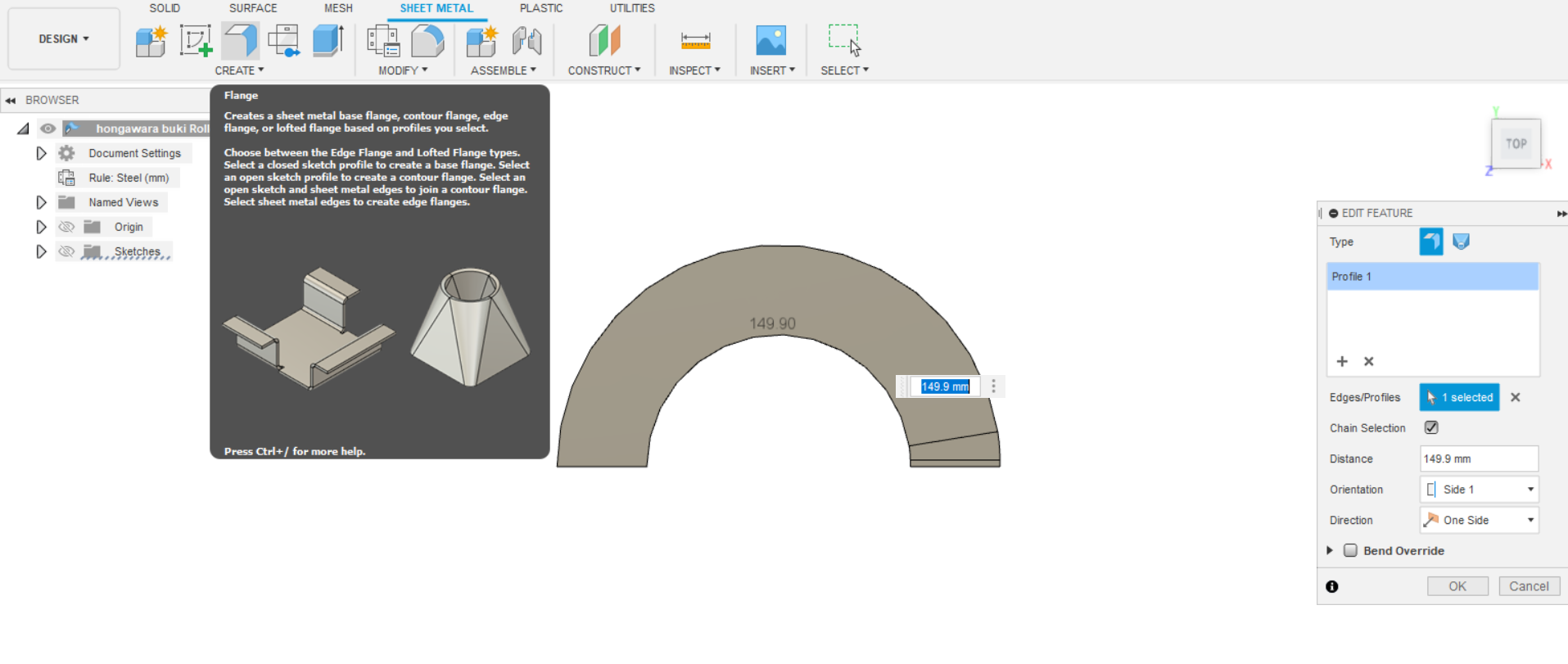
In the Sheet Metal menu, look for the Flange Tool. We'll use this tool to extrude our imperfect semi-circle. Using this tool, we only have select our semi-circle and say how tall we want our part to be. The thickness will be changed later.
Once the Flange operation is complete, we should have a semi-circle with a flat part on the end where we messed around in the previous step.
Changing the Part Thickness
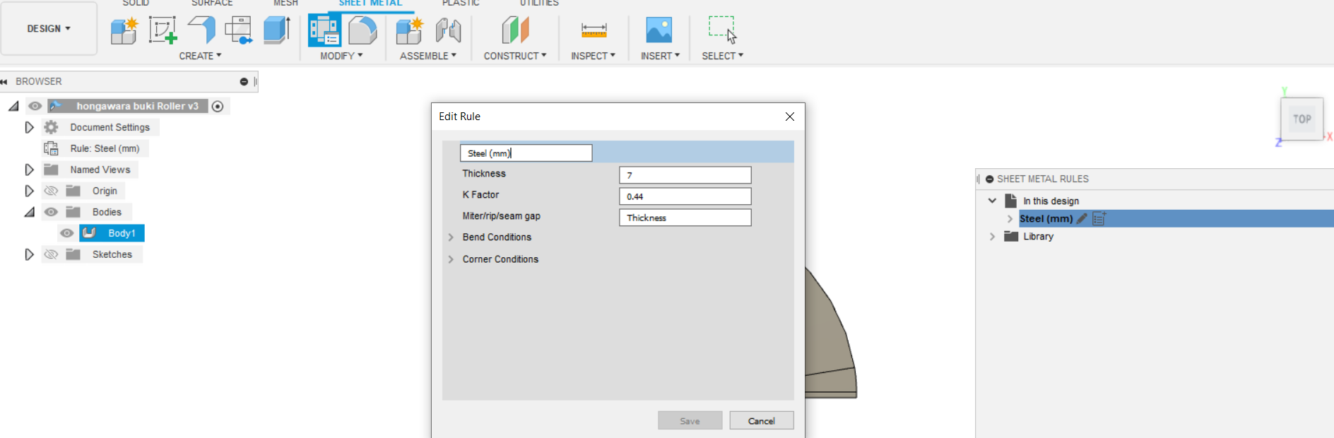
Now we'll change the thickness of our material. Because we're working in the Sheet Metal workspace, things are a little different. To change the thickness of our part, we need to tell Fusion360 what thickness of sheet metal we are supposedly working with.
To do this, click on the Sheet Metal Rules function in the MODIFY menu. On the right, a little dialogue should open which lists the materials used in the current design. It should default to Steel(mm). Hover over it and click the pencil icon which will open yet another dialogue where we can change the thickness.
The thickness can be changed in this manner at any time moving forward.
Quick Little Extrusion
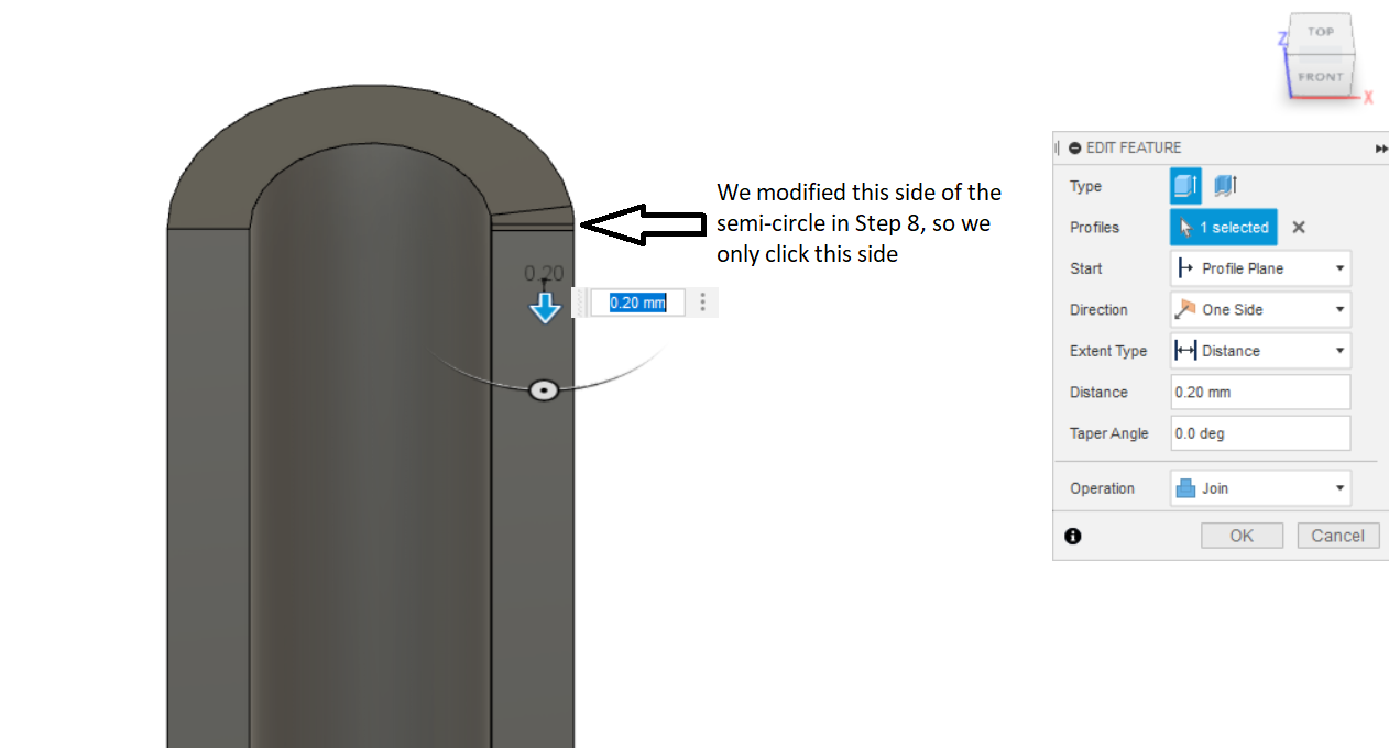
In addition to the modifications to the semi-circle we made in Step 8, we will make a quick little extrusion to help us out in the next steps. Click on the Extrude tool in the CREATE menu and then click on the surface which belongs to the modified semi-circle. We want to extrude this a tiny amount, somewhere around 0.1-0.2 mm.
Import the Tile Rows From Earlier
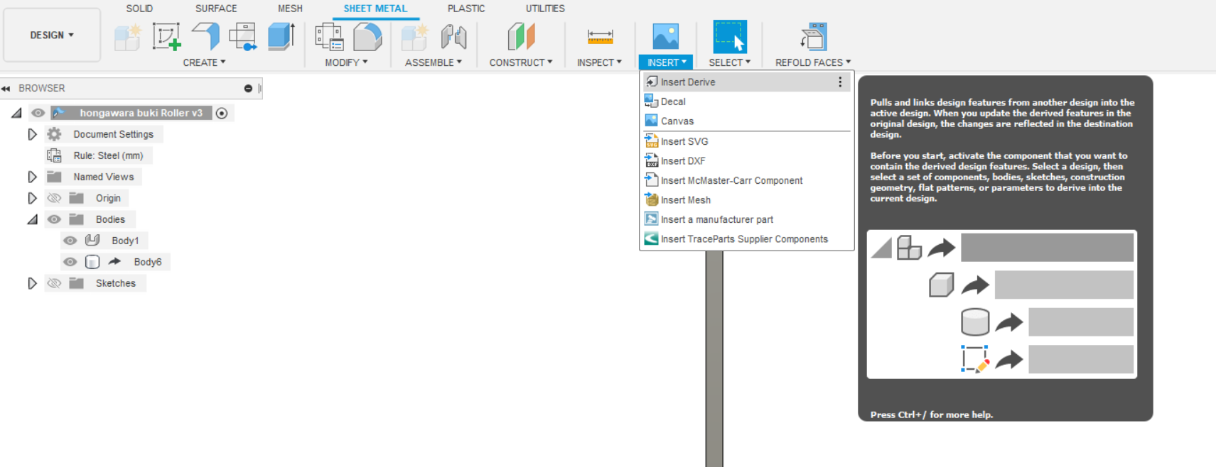
If you made a new file as I did before starting the sheet metal steps, now would be the time to import the tile rows we made earlier. To do so, Click INSERT then click Insert Derive then open the tile rows file to import it. When it does import, it will look transparent.
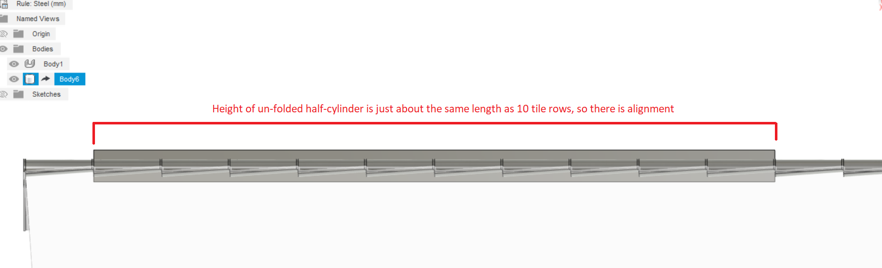
Unfolding Our Semi-Circle/half-cylinder
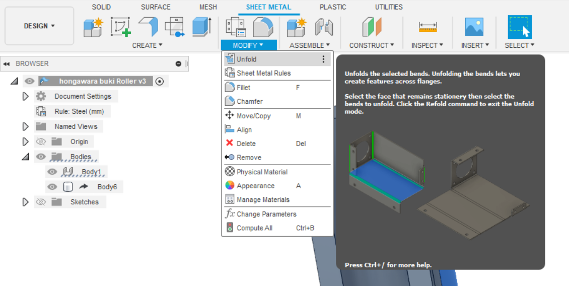
Now the magic of the Sheet Metal workspace is revealed! We're going to flatten out our half-cylinder so that we can take our flat tiles and then make them round again.
Click MODIFY then click on the Unfold tool.
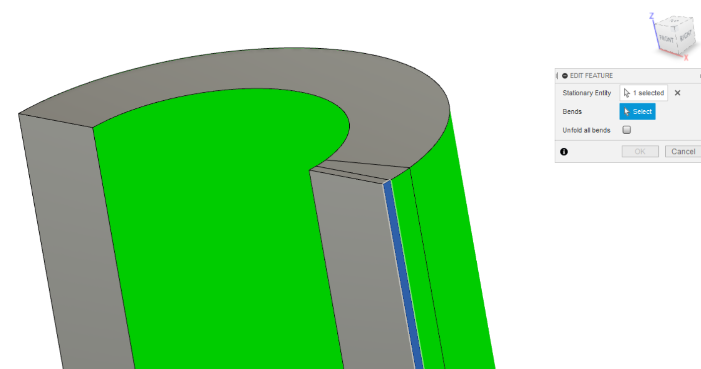
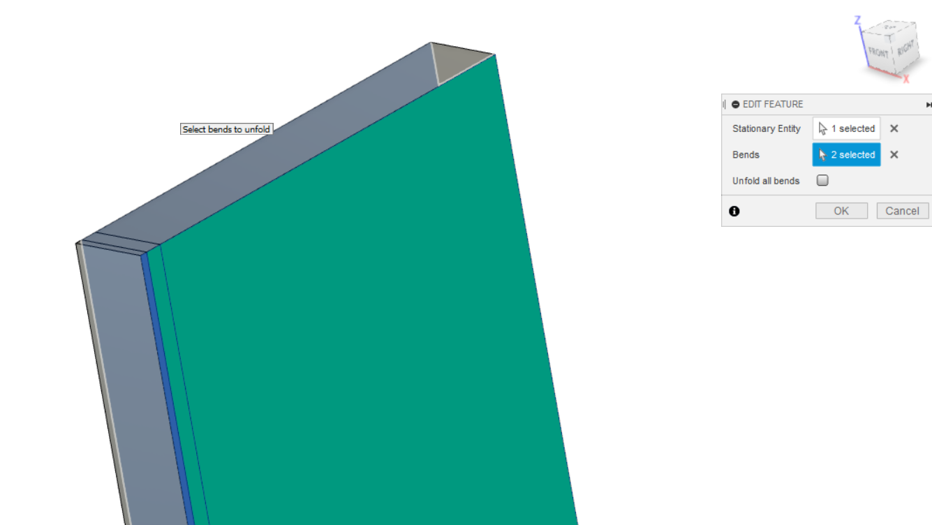
Remember that quick little extrusion we made? Now it comes into play. For the Stationary Entity we want to select the thin rectangle created by that extrusion. If we do it right, then the curved surfaces will turn a bright green. We will select these as Bends. When we do this, our half-cylinder should straighten out into a rectangle. Make sure you select all of the green areas, otherwise your rectangle will have a slight bend in it.
Positioning the Tile Rows

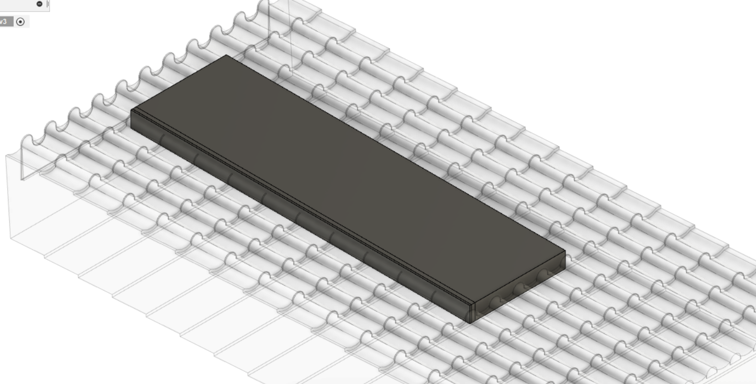
We're on the final stretch now.
Using the Move/Copy tool, we are going to position our tile rows that we imported in Step 12 such that it intersects with our un-folded half-cylinder. What we're going to do in the next step is cut away the tile rows from the un-folded half-cylinder.
You want to position it so that the pattern fits nicely in the un-folded half-cylinder, keeping in mind that we are only making one half of our cylinder, so the pattern would need to wrap around and continue. Looking at the photo should provide a bit more clarity.
If your tile rows do not fit well, go back in the Fusion360 timeline at the bottom of your screen and play around with the diameter of your semi-circle we sketched in Step 8 or by changing the thickness we changed in Step 10.
Cutting Out Our Shape
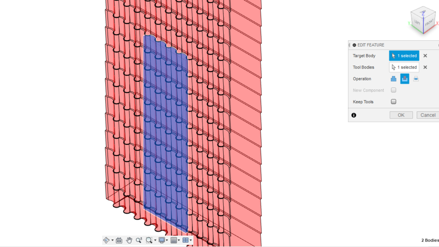
With our un-folded half-cylinder aligned with our tile rows, we want to move back over to the SOLID workspace and select the Combine tool. The Target Body will be our half-cylinder and the Tool Body will be the tile rows. Make sure to select the Cut operation.
Re-Folding Our Half-Cylinder
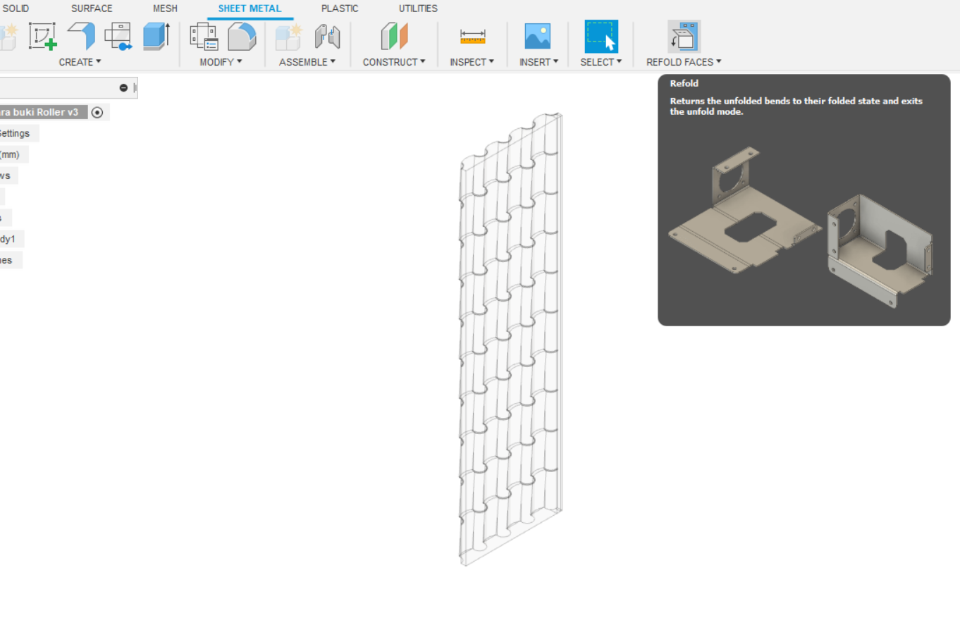
Not much left to do now!
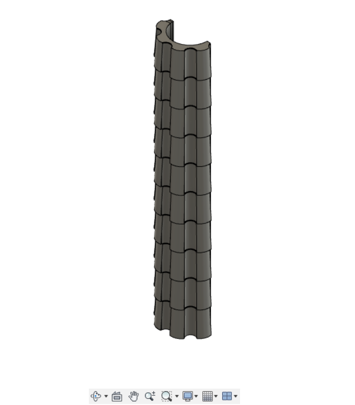
Moving back to the SHEET METAL workspace, we'll click on the Refold Faces tool and boom! A half-cylinder with our pattern cut into it!
Turning Our Patterned Half-cylinder Into a Real Cylinder
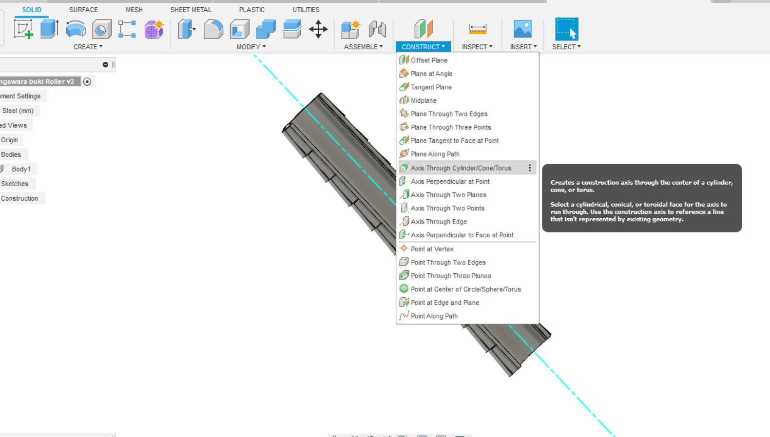
Jumping back to the SOLID workspace, we'll Construct an Axis Through A Cylinder. then click the inside of our half-cylinder.
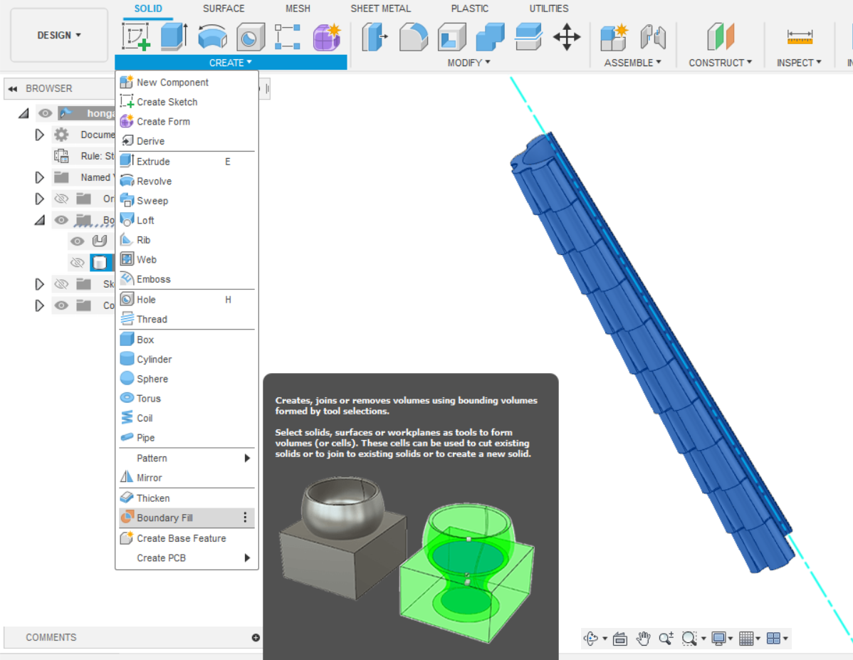
Next, we'll open the CREATE menu and find the Boundary Fill tool. This will turn our sheet metal component into a solid which will allow Fusion360 to manipulate our model easier.
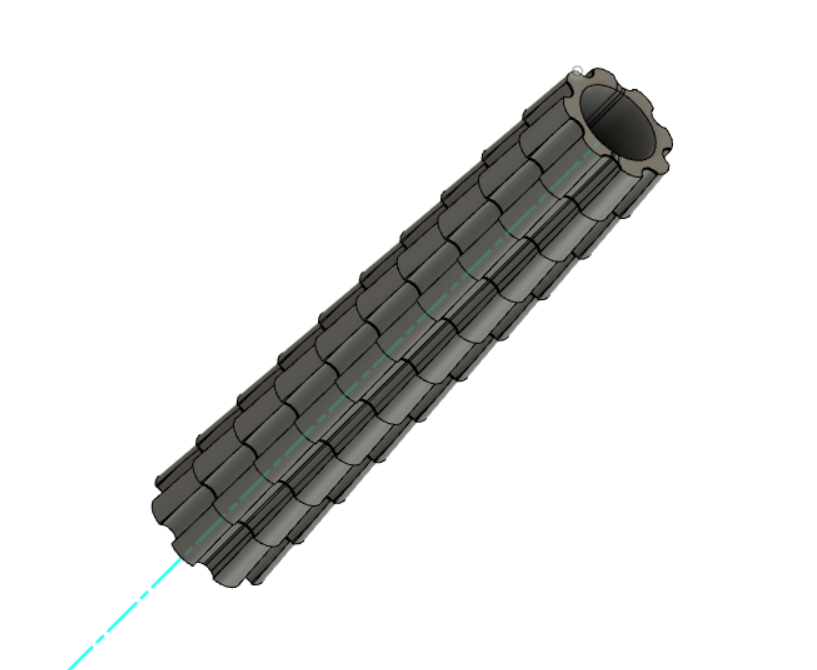
After this, we'll use the Move/Copy tool to create a copy of our half-cylinder and rotate it 180°.
Finally, we will use the Combine tool to join our two halves together to make a full cylinder.
Finishing Touches

At this point, we're good to go!
I recommend that you save your work and then export your part to a .STL and put in it your slicer of choice. Here you should be able to get a better idea of the size and orientation of your completed part.
If it's too big, use the Scale tool in Fusion360, if it's too tall but everything else is good, use the Scale tool but with Non-Uniform scaling in the Z axis.
Play around and modify your roller to your heart's content!
All that's left is to print it and try it out! Have fun!