Robotics on a Budget
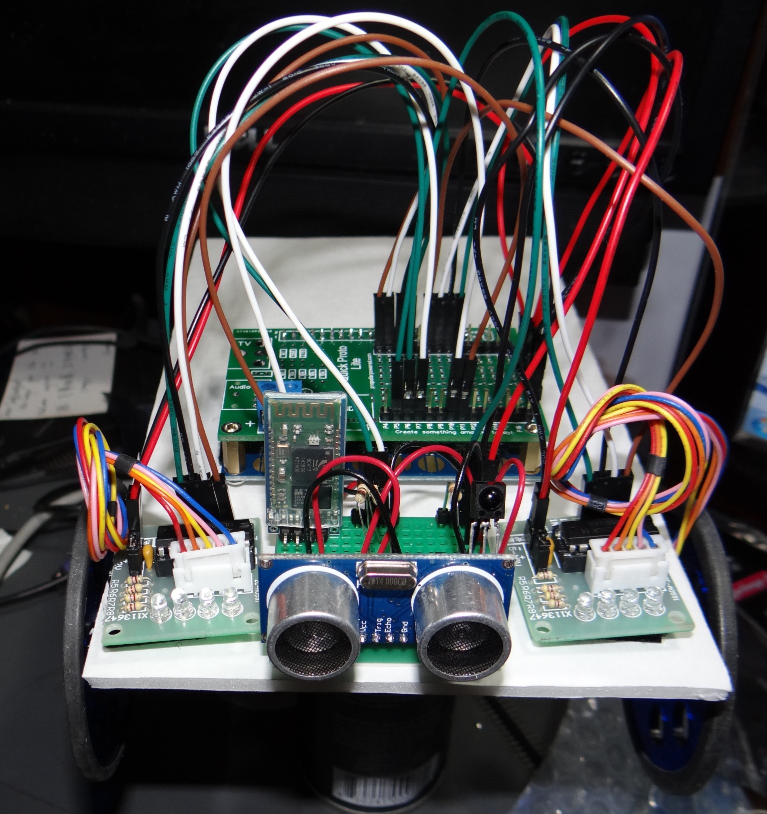
This Instructable will teach you how to create a fun, yet easy to build robot using materials which cost less than fifty dollars.
This is a great project for 4H, Boyscouts or as a classroom introduction to robotics.
I'll teach you how to build and program the robot you see in this picture.
Don't be alarmed by the number of wires you see in the photo!
This Instructable will take you step-by-step to building your robot that has the following features:
While this robot uses a Parallax Propeller as it's brain, you don't have to know anything about programming to get started. I've already blazed the trail ahead of you with programs you can load which will allow you to control it with a simple universal remote control, or in simple BASIC using Bluetooth.
I promise you'll have a great time with this project, perhaps so much so that you'll become hooked on robotics by the end of this project.
This is a great project for 4H, Boyscouts or as a classroom introduction to robotics.
I'll teach you how to build and program the robot you see in this picture.
Don't be alarmed by the number of wires you see in the photo!
This Instructable will take you step-by-step to building your robot that has the following features:
- IR remote control using a Sony compatible remote or universal remote
- Ultrasonic detection using an inexpensive HC-SR04 module
- Bluetooth communication in BASIC to your Bluetooth enabled PC or Android terminal program.
While this robot uses a Parallax Propeller as it's brain, you don't have to know anything about programming to get started. I've already blazed the trail ahead of you with programs you can load which will allow you to control it with a simple universal remote control, or in simple BASIC using Bluetooth.
I promise you'll have a great time with this project, perhaps so much so that you'll become hooked on robotics by the end of this project.
Materials
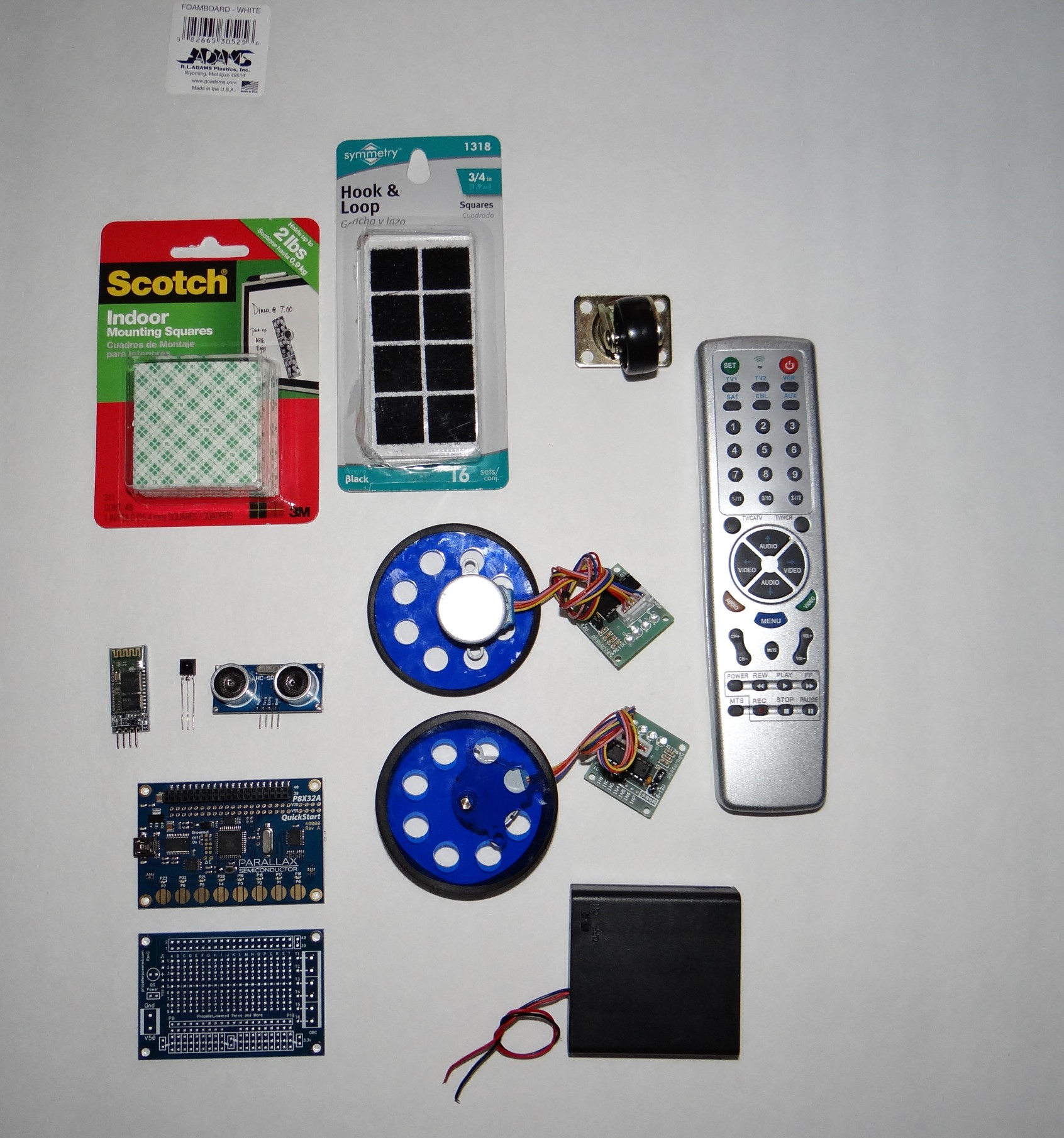
There are several items in this robot which are considered optional, depending on your design requirements. You might choose to add the ability to control your robot using the Ultrasonic sensor, IR remote control. or Bluetooth control at any time. The required materials to build a minimum robot come in under $50.
While the Bluetooth Module is recommended, I show you how to build a version of this robot which only requires the IR receiver, allowing you to control your robot using a universal remote control.
Materials List:
Things you'll probably want: (and probably have already)
Note: Don't skimp on the purchase of the self-stick squares. I chose 3M brand because they are capable of holding quite a bit of weight with a small surface area. This will become important when we mount the motors to the robot. I encountered some dollar self-stick squares when I purchased the foam board. Trust me, spend the extra three dollars here. If money is tight, hot glue will suffice everywhere these squares are used.
While the Bluetooth Module is recommended, I show you how to build a version of this robot which only requires the IR receiver, allowing you to control your robot using a universal remote control.
Materials List:
- Propeller Quickstart Board $25.00 (source: Propellerpowered, comes with a prototyping board)
- Quickstart prototyping board $4.99 (optional)
- Serial Bluetooth Module $8.99 (source: Propellerpowered, Ebay recommended, but optional)
- 2 - 5v Stepper Motors with motor control board $2.99 each (source: Propellerpowered, Ebay)
- Pair of wheels for the stepper motors $3.99 (source: Propellerpowered)
- 4-AA Battery Pack $2.49 (source: Propellerpowered, Ebay)
- 1" 1/4" Caster wheel $1.49 (source: Lowes, Home Depot)
- Foam Board $1.00 (source: Dollar Store)
- 3M Double-sided indoor mounting squares $3.49 (source: Walmart, hot glue may also be used.)
- Hook & Loop (velco) self-stick mounting squares $1.00 (source: Walmart, Dollar Store)
- HC-SR04 Ultrasonic Module $3.49 (source: Propellerpowered, Ebay optional)
- Universal Remote Control $2.99 (source: Propellerpowered, Ebay optional)
- IR Receiver $1.49 (source: Propellerpowered, optional)
Things you'll probably want: (and probably have already)
- A solderless breadboard.
- A few single f/f jumper wires.
- A few single m/m jumper wires.
- A couple 4-pin f/f jumper wires. (or a few more single f/f jumper wires)
- Solder & Soldering pencil
- Male pin headers, and extended pin headers.
- A 10k resistor.
- A 3.3k resistor.
- A 1k resistor.
Note: Don't skimp on the purchase of the self-stick squares. I chose 3M brand because they are capable of holding quite a bit of weight with a small surface area. This will become important when we mount the motors to the robot. I encountered some dollar self-stick squares when I purchased the foam board. Trust me, spend the extra three dollars here. If money is tight, hot glue will suffice everywhere these squares are used.
Introducing the Propeller Tool
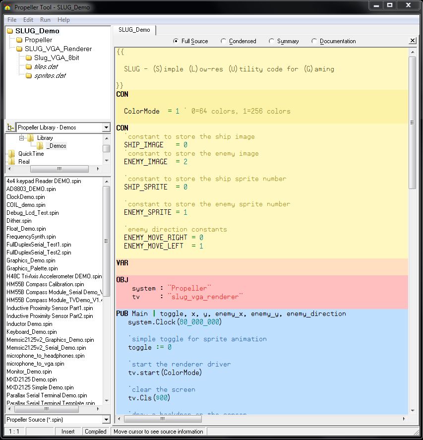
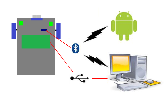
The Propeller Tool is the Windows based software application we'll use for loading the programs required to test the basic functions of the little robot. and install it's BASIC programming language which uses the Bluetooth module.
Initially, we will use a USB connection between the Quickstart board on the robot to both power the robot while testing (over USB) and load the initial test programs using the Propeller Tool. After all the test programs work, we'll use the Propeller Tool to install BASIC which will allow us to disconnect the USB cable and interact with the robot wirelessly from a serial terminal from either a Bluetooth enabled PC or Android device. You will be able to interact with your robot from your desk without having to plug it back into your computer to program it. (A good terminal program, Parallax Serial Terminal is packaged with the install of the Propeller Tool software.)
Download the latest version of Propeller Tool from: http://www.parallax.com/PropellerTool
Install the program using all of the default settings. On the Install Optional Driver step, make sure to leave the checkbox checked for the "Automatically install/update driver" feature. When you double-click the Propeller Tool software link that the installer placed on your desktop for the first time, it will ask you about file associations. Click Yes. (Detailed instructions for this install can be found here.)
Next, connect a USB cable from your Quickstart board to your computer. After a moment or two of automatically locating and installing the correct drivers, you should be ready to go. You can give your configuration a quick test by pressing F7 in the Propeller Tool. You should see the words, Propeller chip version 1 found on COM ##.
Start Building Your Robot: Foam Board
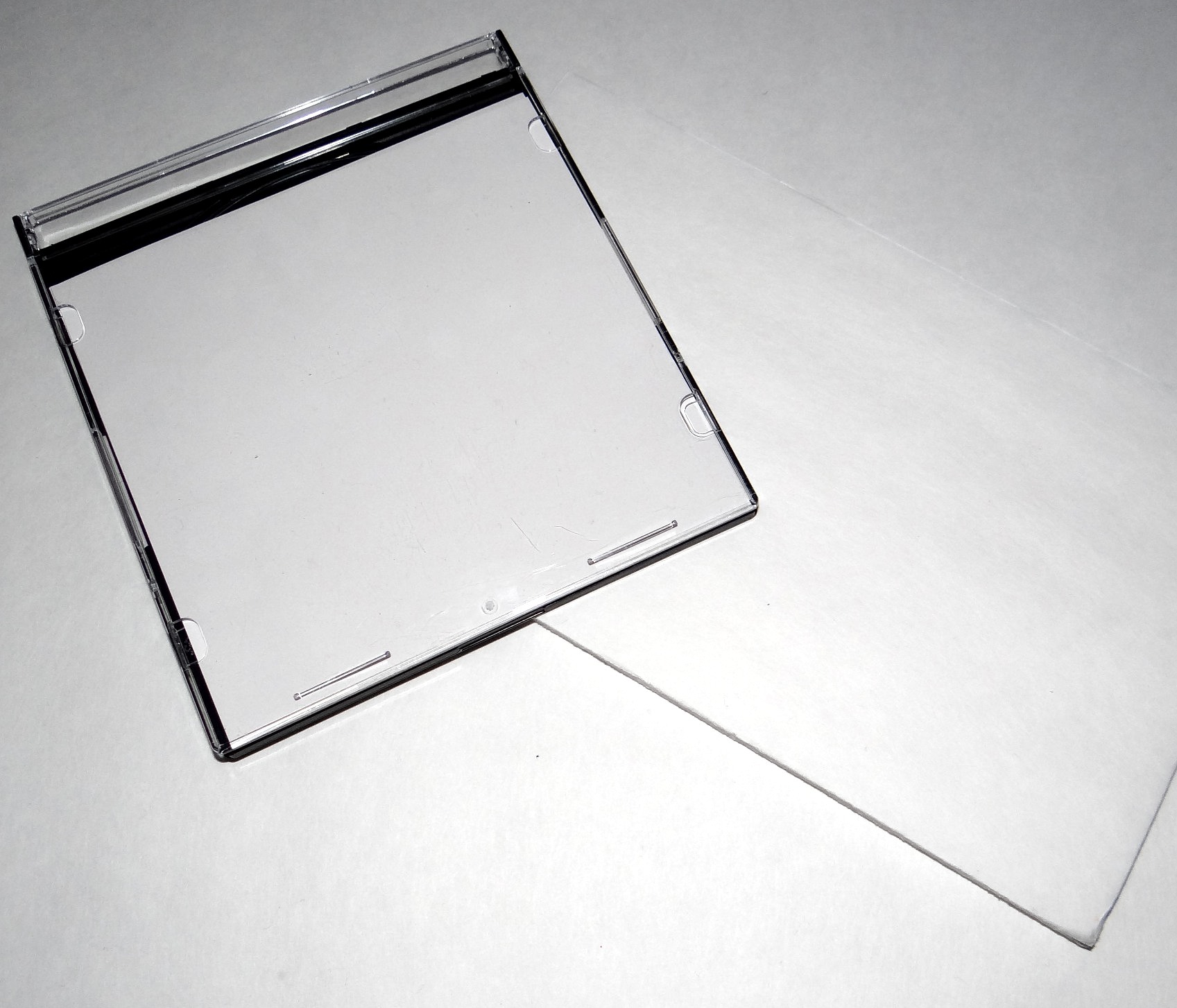
It's time to start actually building this robot! All robots need a base and this one uses inexpensive foam board.
I purchased the foam board from a local "dollar" store for a buck. A single sheet of this material could create an entire robot army!
Use a razor knife to cut a piece of of the material. The size of this board should be around 5" x 8". I used a plastic CD case as my width guide, allowing the length to be a little longer. Don't worry about the exact size! Just try to keep the cut straight so you wind up with a nice rectangle.
Caster Wheel & Battery Pack
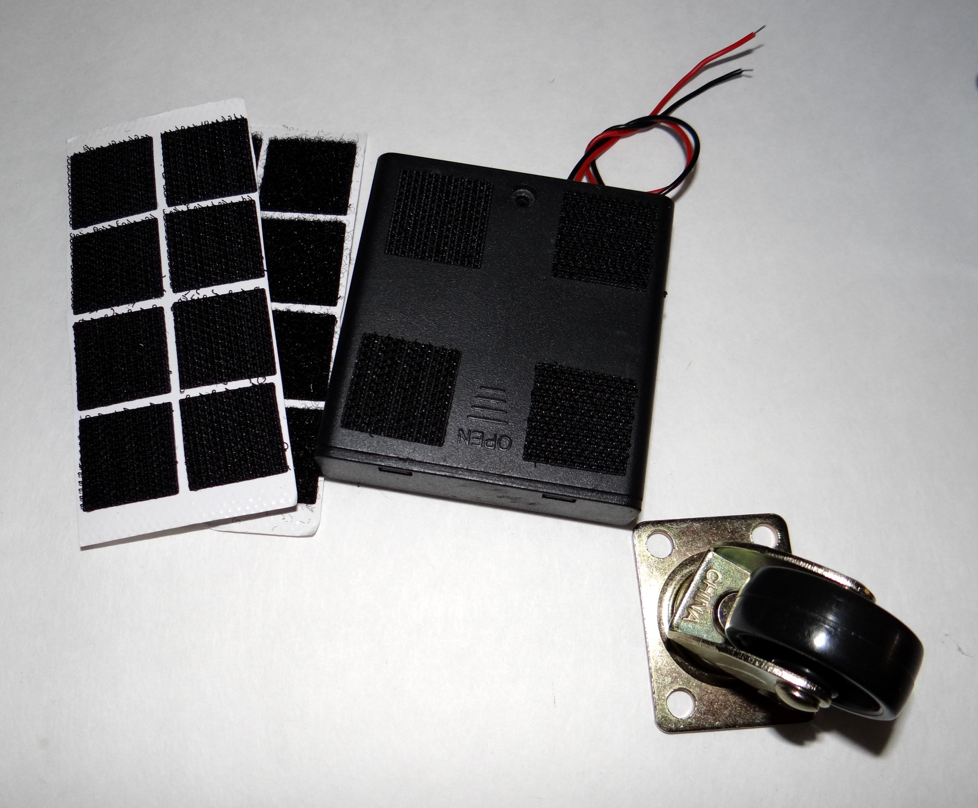
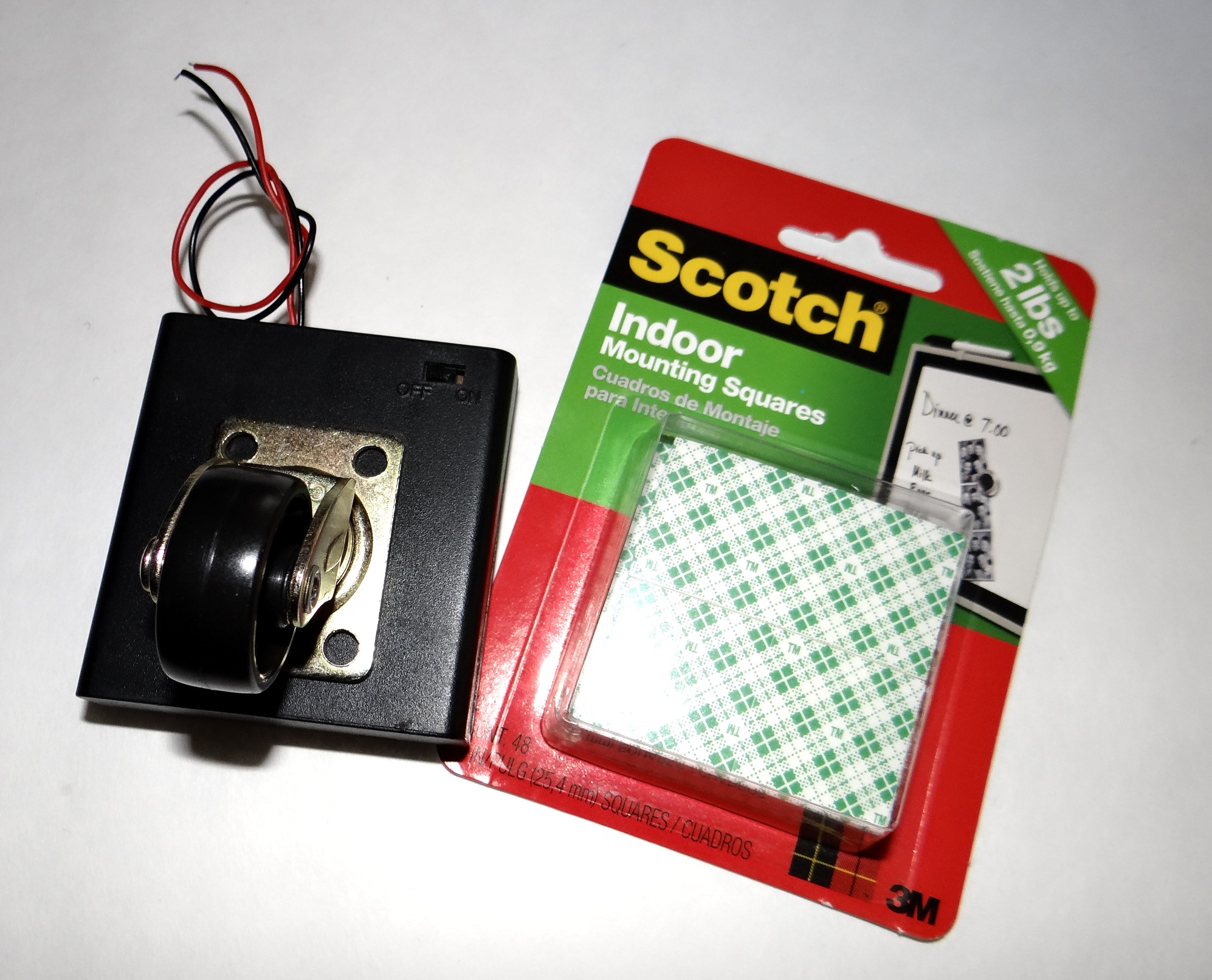
The type of robot we are build is called a "Tail Dragger" because it uses two front drive wheels with a "dragging" wheel behind.
Note (Again): Don't skimp on the purchase of the self-stick squares. I chose 3M brand because they are capable of holding quite a bit of weight with a small surface area. This will become important when we mount the motors to the robot. I encountered some dollar self-stick squares when I purchased the foam board. Trust me, spend the extra three dollars here. If money is tight, hot glue will suffice everywhere these squares are used.
- Attach four of the self-stick "hook & loop" squares to the battery cover side of the battery pack.
- Using the 3M self-stick squares, mount the caster wheel to the switch side of the battery pack.
Note (Again): Don't skimp on the purchase of the self-stick squares. I chose 3M brand because they are capable of holding quite a bit of weight with a small surface area. This will become important when we mount the motors to the robot. I encountered some dollar self-stick squares when I purchased the foam board. Trust me, spend the extra three dollars here. If money is tight, hot glue will suffice everywhere these squares are used.
Mounting the Wheels to the Motors
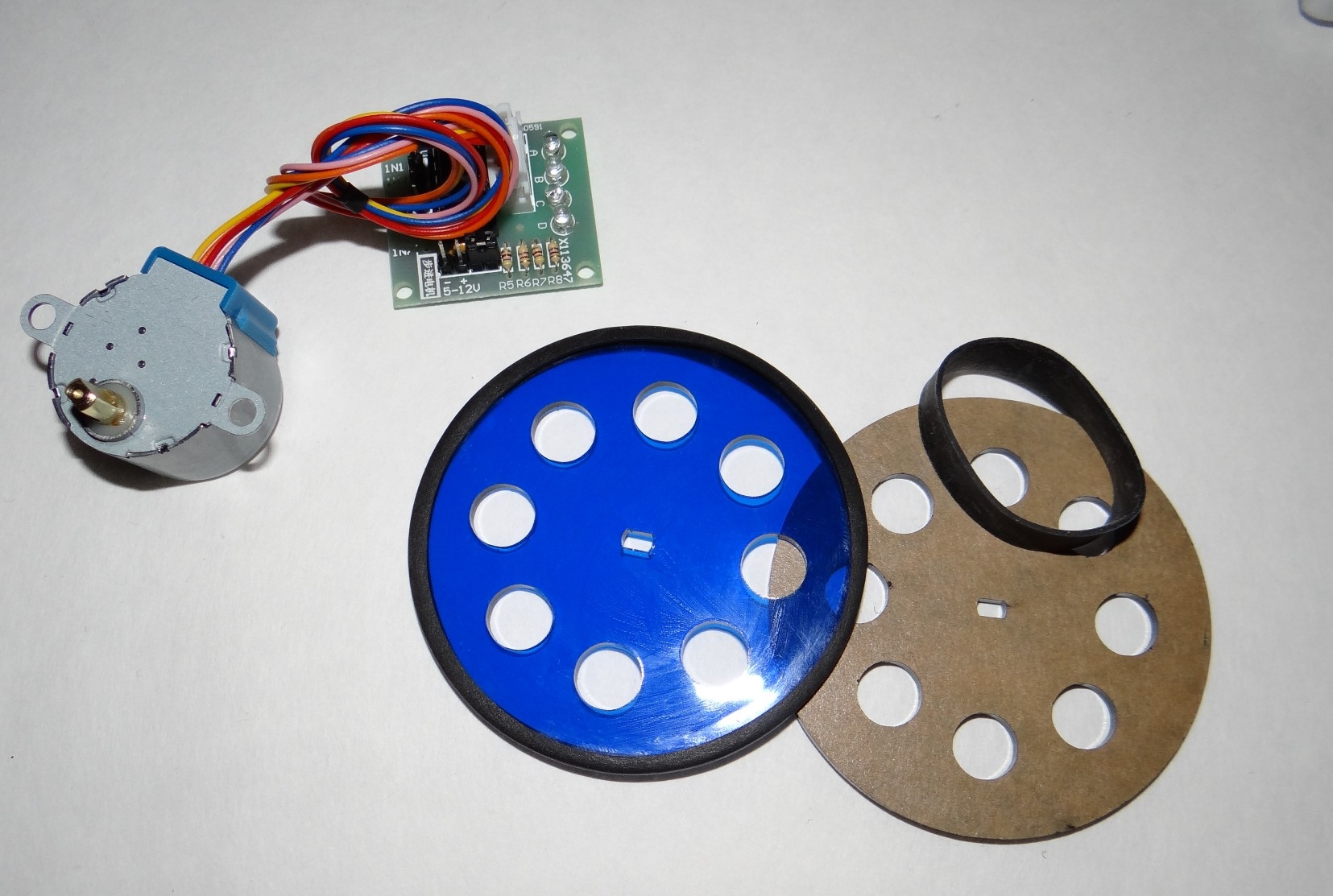
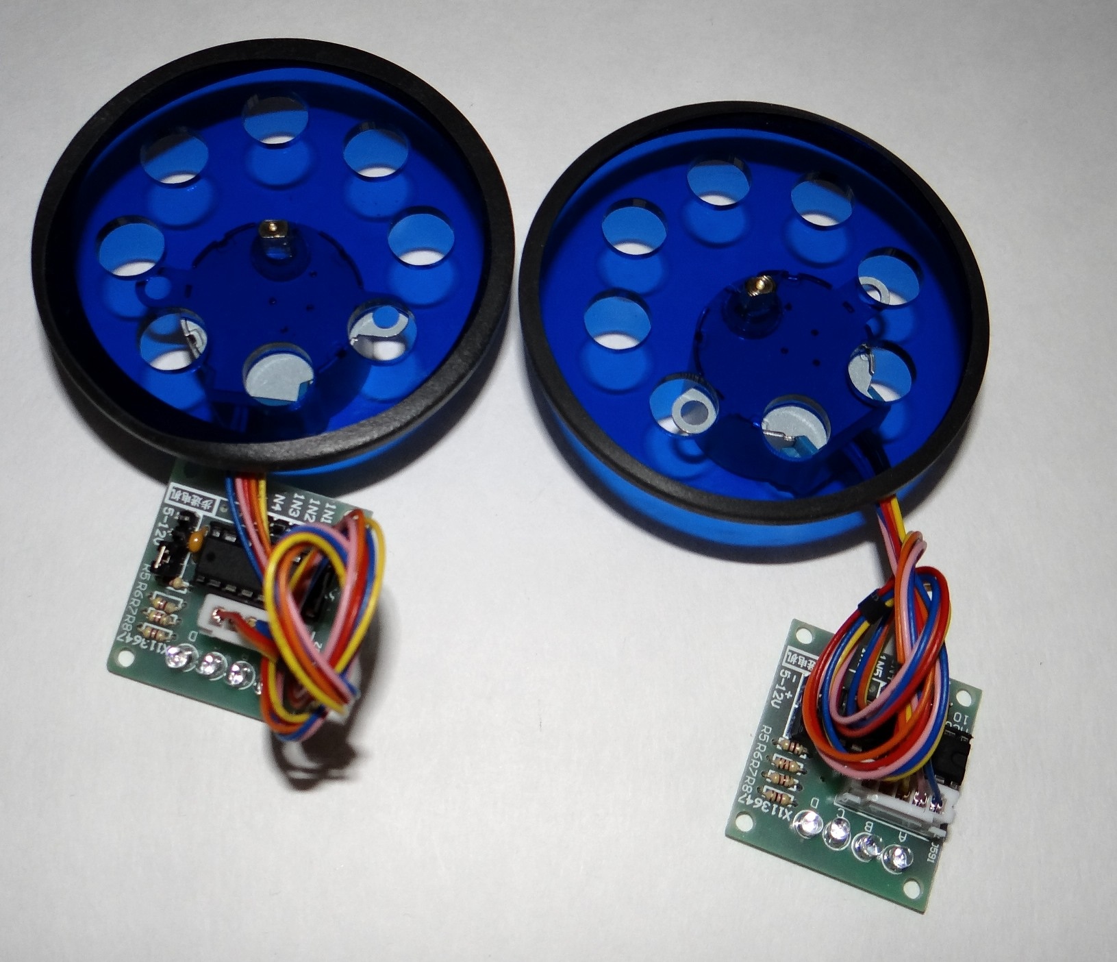
It's time to mount the two front drive wheels.
Note: The motor/wheel fit is "exact". Avoid twisting or flexing the wheel as your press it onto the motor as cracking may occur!
Once the motors are attached to the wheels, they should not be removed.
- Carefully peel the protective, brown film from both sides of the wheel itself.
- Stretch the rubber band around the wheel. You'll probably need a second person to help with this.
- Place the wheel on your desk and press the motor straight down into the wheel mount.
Note: The motor/wheel fit is "exact". Avoid twisting or flexing the wheel as your press it onto the motor as cracking may occur!
Once the motors are attached to the wheels, they should not be removed.
Mounting the Wheels to the Base
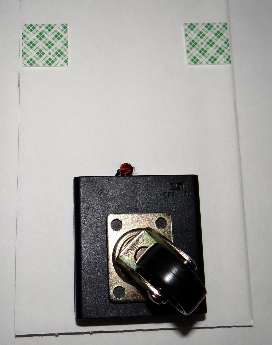
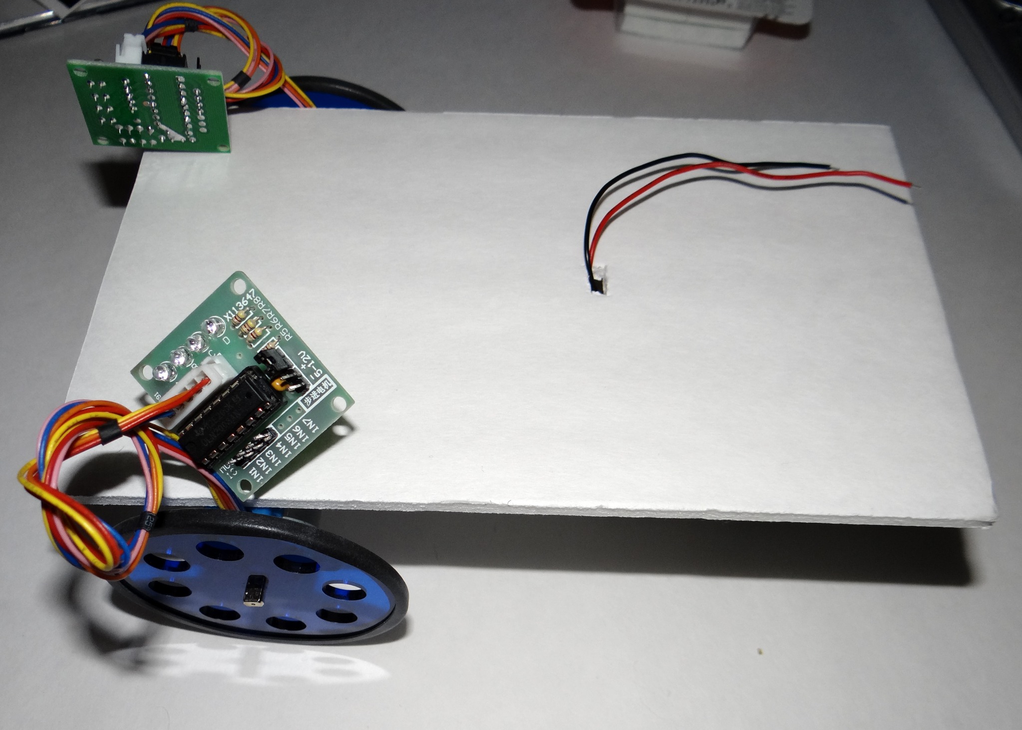
It's time to start putting our robot together so it starts looking like a robot.
Note: While exact positioning, "front-to-back" isn't really critical, do your best to mount the two stepper motors directly across from each other. I used that plastic CD case I used for cutting to align the mounting squares.
- Use other side of the four "hook and loop" squares to attach the battery back to the rear of the foam panel we cut.
- Cut a small hole for the wires from battery pack to go through the foam board.
- Carefully attach the two stepper motors to the either side of the front of the foam panel using the mounting squares.
Note: While exact positioning, "front-to-back" isn't really critical, do your best to mount the two stepper motors directly across from each other. I used that plastic CD case I used for cutting to align the mounting squares.
Attaching the Top Boards
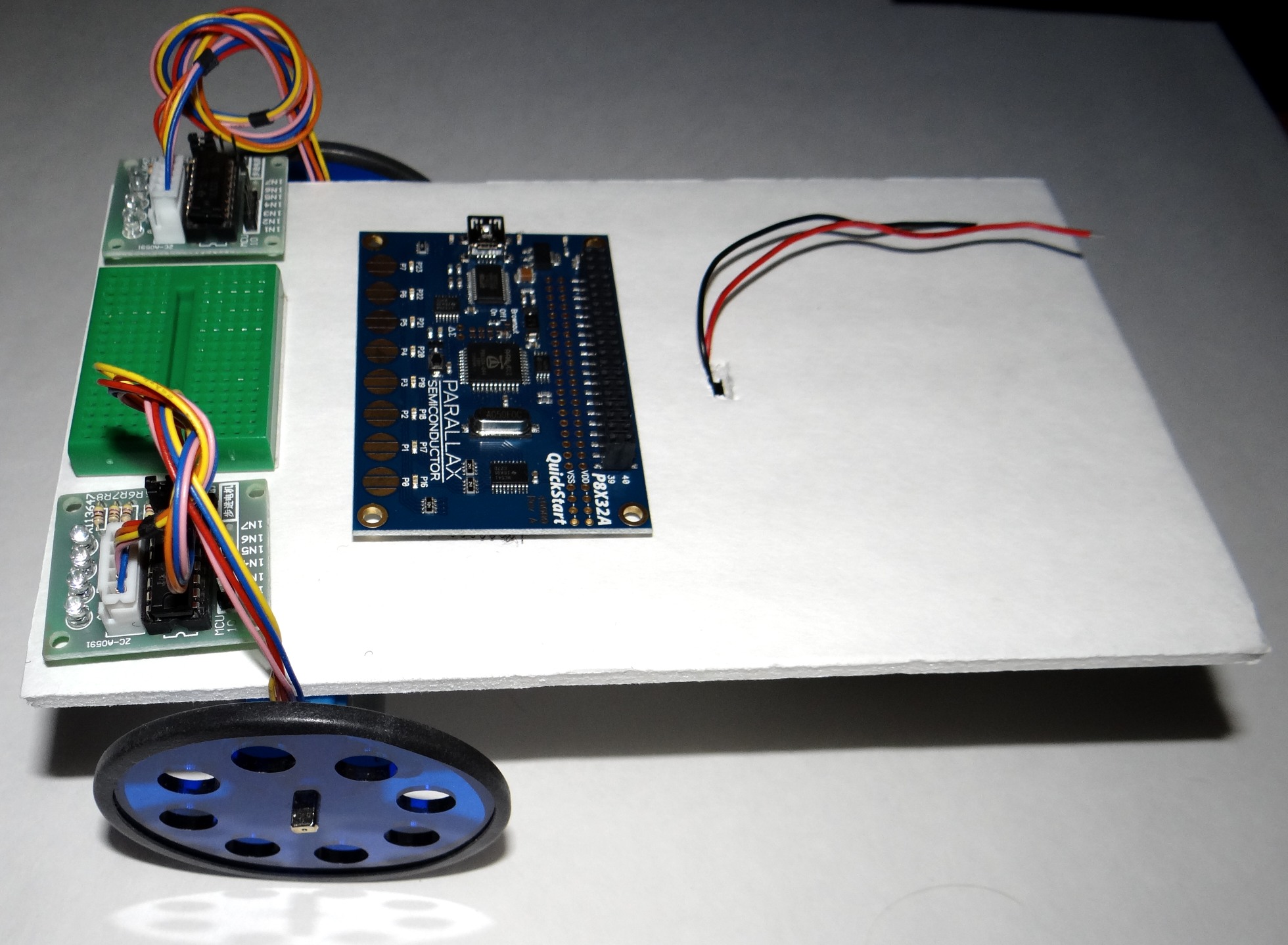
Next, use the "Hook and Loop" squares to mount the two stepper motor motor control boards next to each wheel.
Also, use a couple pieces to attach the Quickstart Board for easy removal.
I had a small self-stick breadboard which I also attached to the front of mine.
Also, use a couple pieces to attach the Quickstart Board for easy removal.
I had a small self-stick breadboard which I also attached to the front of mine.
Shield (board) Options
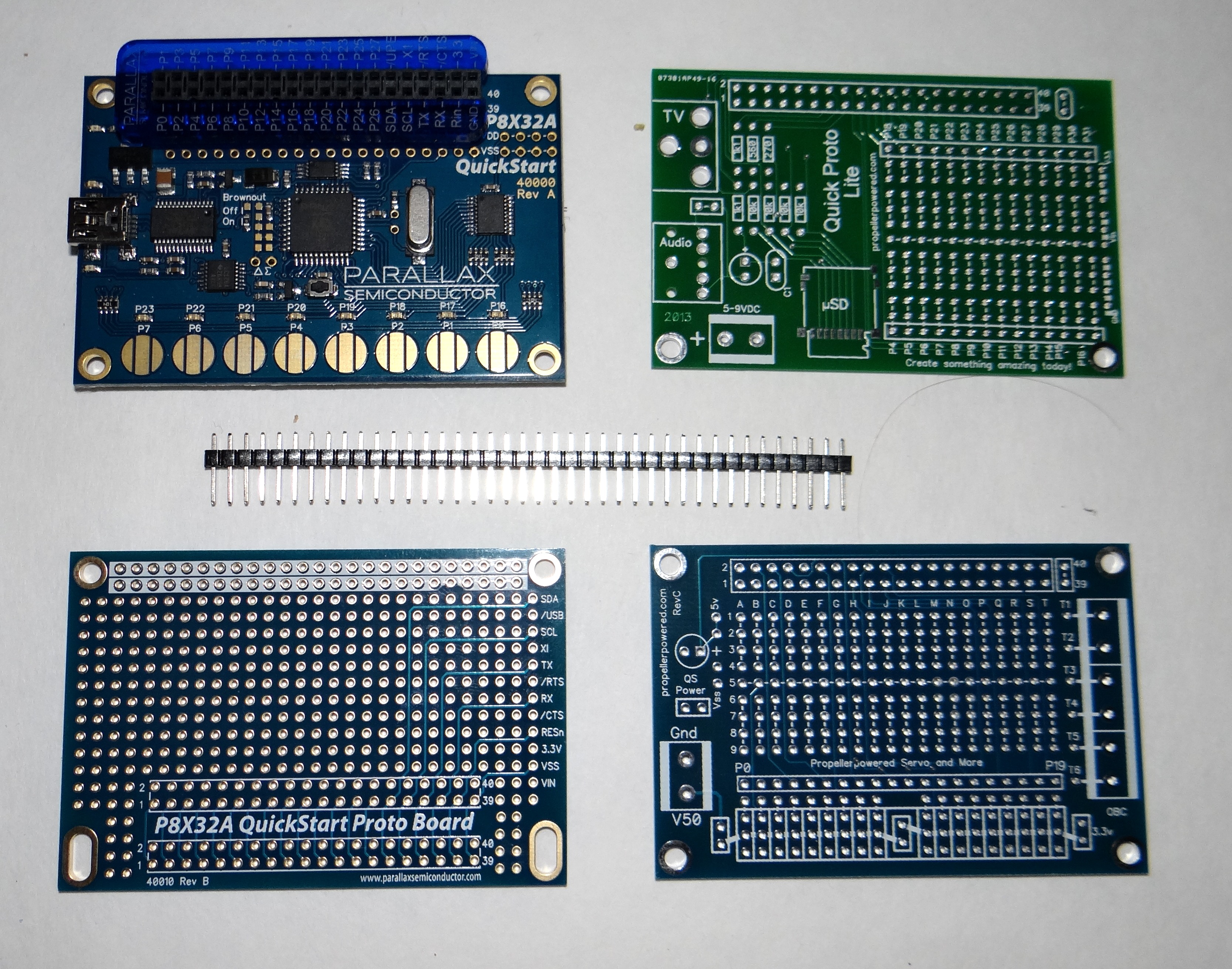
Here's the fun part! Building the robot is like baking a cake. What goes on top is the frosting and you get to decide the flavor!
What you plug into the top of your robot is determined by your personal style and budget.
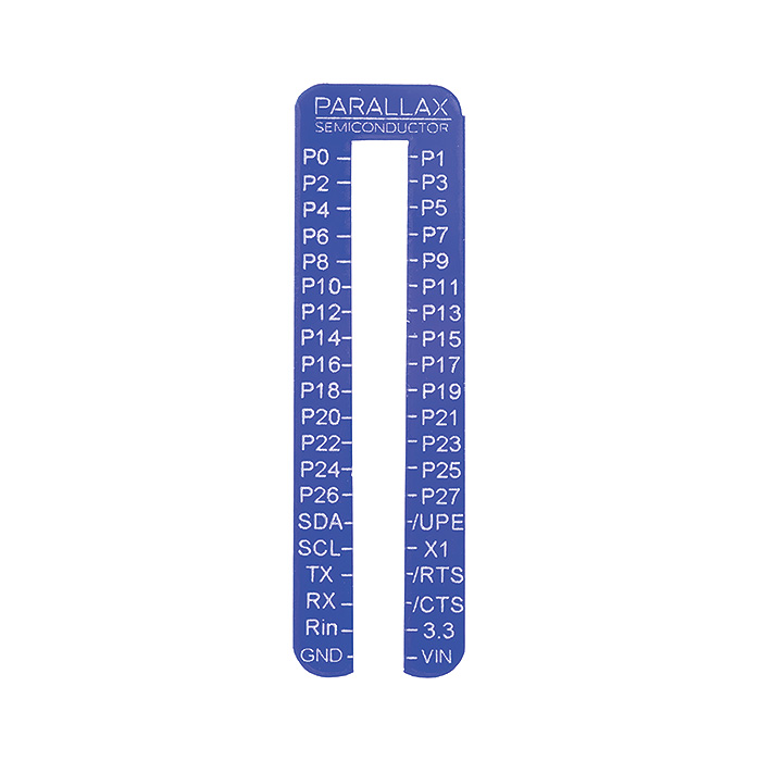
If you use a simple breadboard like I did in the last step, you could simply jumper wires directly from the 40pin head of the Quickstart board to the breadboard, then onto your devices. I've attached a "Pin Finder" (picture 2), available from Parallax or Propellerpowered which will help in understanding the I/O layout of the connector. Just slide the plastic Pin Finder onto the connector until it snaps into place.
A printable version of the Pin Finder can also be found here:
The green board to the right of the Quickstart is the "Quick Proto Lite" board. It has connections for TV and Audio which you probably won't use for a robot, but it also has the ability to power your Quickstart and have a microSD socket added. (At the time of the writing of this document, the Quick Proto Lite board is being provided free with the purchase of a Quickstart from Propellerpowered.com making it a good deal.)
The P8X32A Quickstart PCB pictured directly below the Quickstart is also an economical option which costs only $4.99 from both Propellerpowered and Parallax requiring on a 40pin male header (pictured) to adapt it to the Quickstart)
Finally, in the lower right is the Propellerpowered "Servo & More" board which can be also be configured to power the Quickstart with plenty of prototyping area for your robot.
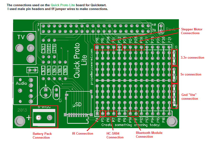
The important part is that you power the Quickstart itself, providing power for the rest of the robot, and have access to a portion of the Propeller's I/O. (In my examples, I'll be using the "Quick Proto Lite" board which comes with the Quickstart from Propellerpowered. See third image for connection points.) From here out, I'll specify the voltages and schematics in general terms so that you'll have success no matter which Propeller board configuration you use.
Connecting the Motors
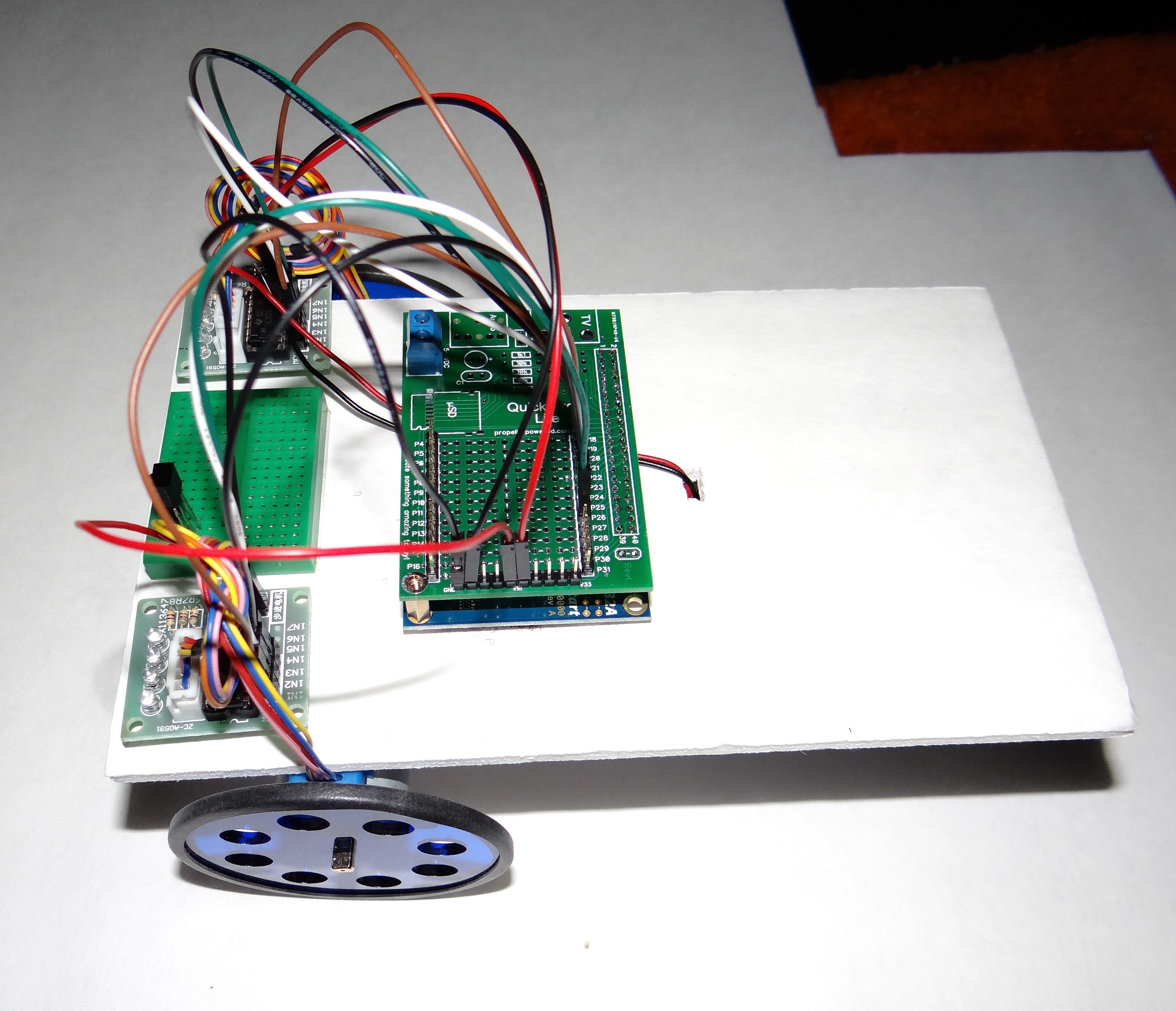
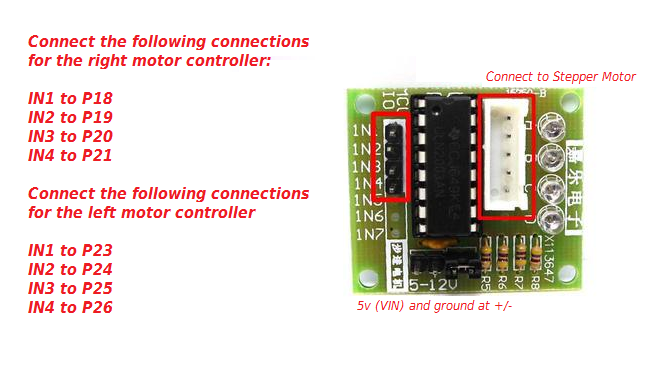
Using jumper wires, make the following connections between your Propeller board and the motor controllers:
Right Motor:
Left Motor
Also connect 5v/Vss to the +/- connections on each board.
I've provided a simple test program which will turn the motors both forward, then backward a full rotation. You download it here: Use Propeller Tool to open this object and F10 to send it your robot.
Explanation:
Stepper motors work by energizing internal coils in progression. In this case, our stepper motors have four coils which activate in AB-BC-CD-DA combinations. We activate the lines in a 1100,0110,0011,1001 progression on one wheel, and because the motor on the opposite side is mounted the other direction, we use 1001,0011,0110,1100 at the same time to spin the wheel in the other direction. This causes the both wheels to move the same direction at once, propelling our robot forward or backward with the test program.
Right Motor:
- IN1 to P18
- IN2 to P19
- IN3 to P20
- IN4 to P21
Left Motor
- IN1 to P23
- IN2 to P24
- IN3 to P25
- IN4 to P26
Also connect 5v/Vss to the +/- connections on each board.
I've provided a simple test program which will turn the motors both forward, then backward a full rotation. You download it here: Use Propeller Tool to open this object and F10 to send it your robot.
Explanation:
Stepper motors work by energizing internal coils in progression. In this case, our stepper motors have four coils which activate in AB-BC-CD-DA combinations. We activate the lines in a 1100,0110,0011,1001 progression on one wheel, and because the motor on the opposite side is mounted the other direction, we use 1001,0011,0110,1100 at the same time to spin the wheel in the other direction. This causes the both wheels to move the same direction at once, propelling our robot forward or backward with the test program.
Adding IR Ability to Control Your Robot
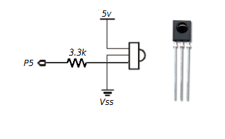
Next, let's add some basic control to our robot.
Add the IR receiver with the following connections: (with it facing you)
Using a Sony compatible remote control, use 2 to for forward, 8 to go backward, and 4 & 6 to go right and left.
Add the IR receiver with the following connections: (with it facing you)
- Connect the right-most pin to 5v
- Connect the middle pin to Vss (ground)
- Connect the left-most pin to a 3.3k resistor, then to P5
Using a Sony compatible remote control, use 2 to for forward, 8 to go backward, and 4 & 6 to go right and left.
Add Ultrasonic Vision to Your Robot
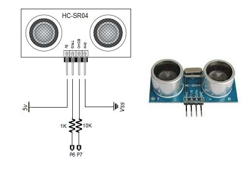
In addition to IR control, we can also give our robot the ability to see an obstacle in it's path and avoid it.
The HC-SR04 Ultrasonic module gives your robot the ability to see using sonar to determine distance to an object like bats or dolphins do.
Here's how to add an HC-SR04 Ultrasonic sensor to your robot.
HC-SR04 Specifications:
Download this program, extract and send "Avoid Objects.spin" to your robot using F11 from the Propeller Tool.
The HC-SR04 Ultrasonic module gives your robot the ability to see using sonar to determine distance to an object like bats or dolphins do.
Here's how to add an HC-SR04 Ultrasonic sensor to your robot.
- Connect 5v from the Quickstart VIN to the HC-SR04 Module
- Connect TRIG to a 1k resistor, then continue to P6.
- Connect ECHO to a 10k resistor, then continue to P7.
- Connect Gnd to Vss
HC-SR04 Specifications:
- Power Supply :5V DC
- Quiescent Current : <2mA
- Effectual Angle: <15°
- Ranging Distance : 2cm – 500 cm/1" - 16ft
- Resolution : 0.3 cm
Download this program, extract and send "Avoid Objects.spin" to your robot using F11 from the Propeller Tool.
Adding Bluetooth Communication
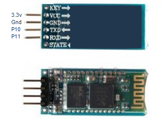
Your robot should be doing all of the basics by now. Rolling forward, backward, avoiding obstacles, and accepting some IR commands.
All of these functions have been accomplished using little pre-written test programs written in Propeller Spin.
Ready to do some real robot programming? I promise it won't be difficult!
Let's add a Serial Bluetooth module and control the robot from a Bluetooth enabled PC or Android using a simple terminal program in BASIC.
Make the following connections between the Bluetooth Module and the Quickstart:
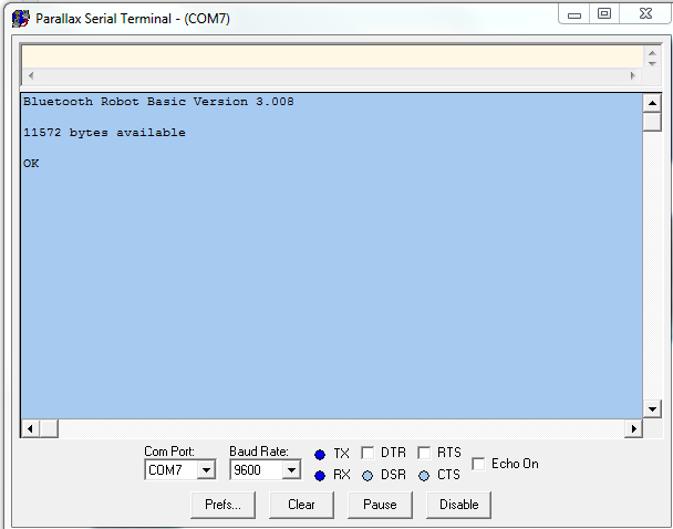
Establish what COM port the Bluetooth is using by connecting to it and using it's default passcode of 1234. Once you know the COM port, open the Parallax Serial Terminal that installed automatically with the Propeller Tool and set it for 9600 baud using that port.
If you need some detailed help with setting up Bluetooth on the Propeller, I've written another tutorial on the subject which can be found at: http://propellerpowered.com/shop/?page_id=1748
Now we can start programming the robot in BASIC.
All of these functions have been accomplished using little pre-written test programs written in Propeller Spin.
Ready to do some real robot programming? I promise it won't be difficult!
Let's add a Serial Bluetooth module and control the robot from a Bluetooth enabled PC or Android using a simple terminal program in BASIC.
Make the following connections between the Bluetooth Module and the Quickstart:
- Bluetooth VCC to 3.3v
- Bluetooth Gnd to Vss
- Bluetooth TXD directly to P10
- Bluetooth RXD directly to P11
Establish what COM port the Bluetooth is using by connecting to it and using it's default passcode of 1234. Once you know the COM port, open the Parallax Serial Terminal that installed automatically with the Propeller Tool and set it for 9600 baud using that port.
If you need some detailed help with setting up Bluetooth on the Propeller, I've written another tutorial on the subject which can be found at: http://propellerpowered.com/shop/?page_id=1748
Now we can start programming the robot in BASIC.
Programming Your Robot in BASIC
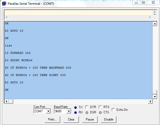
Remember BASIC from computers gone by?
10 PRINT "HELLO WORLD"
20 GOTO 10
Your robot can now be programmed in BASIC! (and yes, the above program works too!)
Here are a few specific BASIC commands for controlling your robot!
FORWARD {cycles} (Moves the robot forward # coil cycles: Example FORWARD 512)
BACKWARD {cycles} (Moves the robot backward # coil cycles: Example BACKWARD 512)
RIGHT {cycles} (Moves only the right stepper forward # coil cycles)
LEFT {cycles} (Moves only the left stepper forward # coil cycles)
HCSR04 (contains the current range from the HCSR04 sensor)
There's a whole list of other BASIC commands your robot will accept included in the archive.
Try the following BASIC program to create a simple obstacle avoidance program in BASIC.
10 FORWARD 150
20 PRINT HCSR04
30 IF HCSR04 < 150 THEN BACKWARD 200
30 IF HCSR04 < 150 THEN RIGHT 250
40 GOTO 10
This program is a simple loop that moves the robot forward 150 cycles, checks to see if there is an obstacle If an obstacle is found, then the robot goes backward 200 cycles, turns right 250 cycles and goes forward again.
Here's some additional ideas:
1) Add an LED or small speaker and use the OUTA command in BASIC to light an LED or make a sound when moving or detecting an object.
2) Change your robot to an obstacle seeker by finding an object, going toward it and stopping in front of it.
3) Visit the Propellerpowered forums and share your robot programming ideas. http://forums.propellerpowered.com