Robotic Car From Raspberry PI
by Param Desai in Circuits > Raspberry Pi
2140 Views, 1 Favorites, 0 Comments
Robotic Car From Raspberry PI
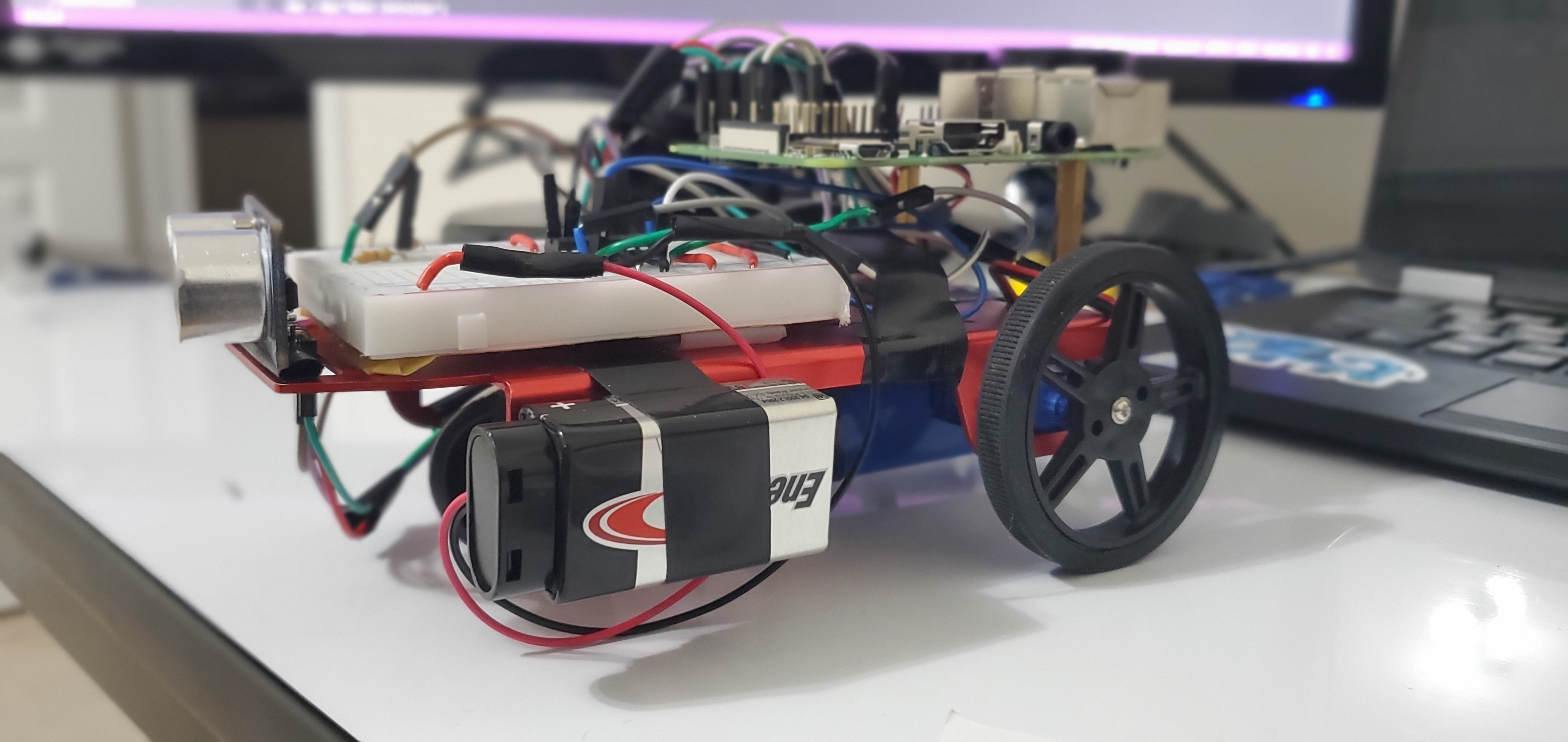
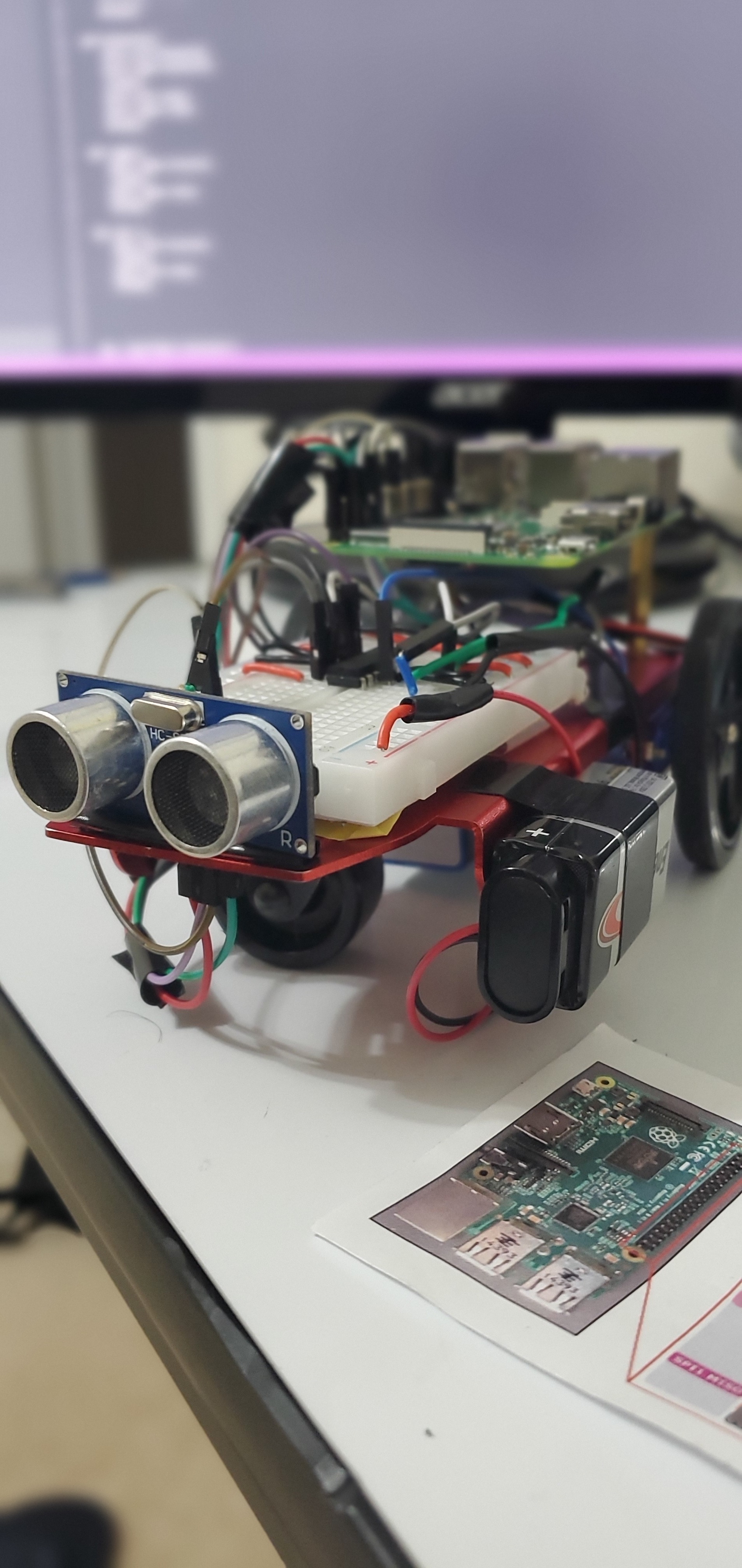
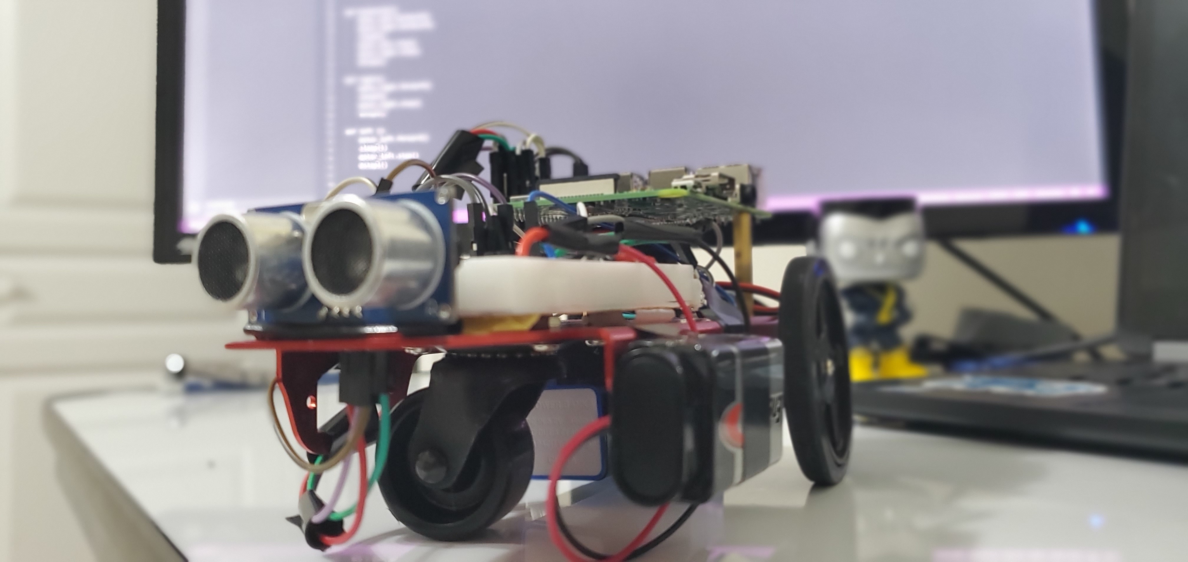
This project is a robotic car made with Raspberry Pi. It can run with a program on mobile phones with controls like going forwards, going backwards, turning right and turning left. Another way is that the car can run by itself without any controls.
Supplies
- Raspberry Pi
- A small Breadboard
- System Smart Robot Car Chassis (Could buy here https://www.alibaba.com/product-detail/FEETECH-FT-MC-001-2WD-4WD_60361963086.html)
- Some Female to Male Wires
- Jumper Wires
- Distance Sensor
- 9-Volt Battery
- l293d chip
- An Android Phone or iPhone to control the car
- 330Ω Resistor
- 470Ω Resistor
Attaching the Raspberry Pi on the Chassis
DC Motors are really easy to connect. The only thing to connect them is to screw them on to the place given with the wheels that are in the kit that come with the chassis.
After that, you need to take the Pi and connect it into the chassis. So it doesn't fall off when the car starts running. First, take off the mounting on the chassis with a screwdriver. Now use the same screws to attach it with chassis on the support beams.
Another 2 things to add on the chassis are the breadboard and the 9-volt Battery. First, tape the breadboard to the front of the chassis and then tape the 9-volt battery to the side of the chassis.
Using the L293D Chip
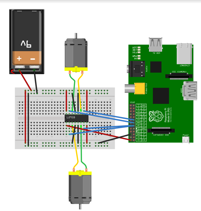
The L293D chip is the most important thing in the car because the H-Bridge helps control the DC motors in the car.
There are a couple of components in wiring the H Bridge.
After placing the L293D chip on the breadboard attach red jumper wires from the 3 corners(don't attach one jumper on the right side of the little chip on the L293D chip.). And connect them on the power rail marked in red on the breadboard.
After that connect the black jumper wires from the two middle sections to the ground power rail marked blue on the breadboard.
Now pull a wire from the 5volt pin from the Raspberry Pi and connect it to the last corner on the L293D chip.
Now we have to connect the motors to the second pins from the end of the L293D chip. The motors are given with two wires connect them both on one side. And the other two wires from the other motor to the other side of the L293D chip. Next part is to connect the GPIO pins to the l293d chip. First pull a wire from the GPIO 4(pin 4) then connect it to the second pin from the last pin on the l293d chip on the right side of the l293d chip. Now pull another wire from GPIO 17 (pin 11) and plug it in the pin that is not used. Now do the same thing with the other two GPIO pins in the left side of the l293d chip (use GPIO 16 and GPIO 20).
Make sure to connect this properly and not mess up.
And connect a wire from the red railing to the red railing on the other side of the breadboard and do the same for the blue railing.
The wiring should kind of look like the schematic on top
Coding the L293d Chip
After carefully wiring the H Bridge we have to code it to run the motors. This is going to be coded on a Python IDE on the Raspberry Pi
Before coding any of the compartments we have to import all of the libraries from the python. The code for that is
from gpiozero import DistanceSensor, Motor #For the Motors and the Distance Sensor from the GPIO library
from guizero import App, PushButton #for the app that is going to control the car
from time import sleep #sleep to make it reasonable
Now we have to initialize the two motors in the car.
motor_left = Motor(forward=19, backward = 26) #for the left Motor
motor_right = Motor(forward=4, backward = 17) #for the right Motor
After initializing the motors we have to test them if they are working or not.
Try this code on your Python IDE to test the motors out:
motor_left.forward()
motor_right.forward()
sleep(3)
motor_left.stop()
motor_right.stop()
motor_left.backward()
motor_right.backward()
sleep(3)
motor_left.stop()
motor_right.stop()
Setting Up the GUI
Now we need to start making the app for the robot. We are going to use the GUI library
If the GUI Library isn't installed in your PI then we are going to do that first.
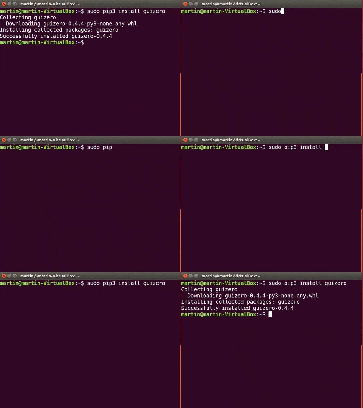
Go on Terminal on the PI and type
sudo pip3 install guizero
into the terminal. After a couple of seconds, the GUI should be installed.
Adding the GUI for the Robot

Now that we have GUI on our Raspberry Pi, we need to use it to make a controller for the Robot. Starting with making functions for each move (forwards, backwards, right and left)
Start by making the forwards function like this:
def forwards():
motor_left.forward()
motor_right.forward()
sleep(1)
motor_left.stop()
motor_right.stop()
Now make the other function for backwards with replacing the forward with backward
And then, we need to make the right and left function. Which is
def right():
motor_right.forward()
sleep(1)
motor_right.stop()
stop1()
Now do the same thing with left by replacing the left with right
After making the function, we have to make the actual buttons on the app. First, we are going to initialize the app by using this command
app = App("Robot Controller")
After this, we have to make the Push Buttons on the app. It consists of using the functions that we already made. An Example for forwards is:
drive = PushButton(app, forwards, text = "Forwards")
Now do the same thing for the other functions(backwards, right and left) After that we need just one code to display the app, which is
app.display()
Now run it and test out the code
Wiring the Distance Sensor
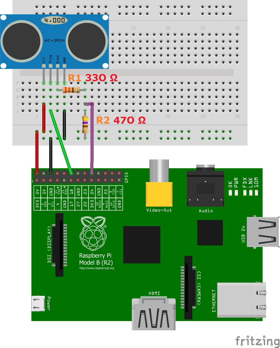
The distance sensor has 4 compartments which are VCC, TRIG, ECHO and GND.
First, we are going to connect the VCC to the 5-Volt GPIO pin with wire. And Connect the GND with a GND GPIO pin with another wire.
The second part is to connect the Trig to any GPIO pin.
Now we have to connect the Echo. The Echo first goes on the breadboard and then connect a 330Ω resistor then connect another wire that connects with 330Ω resistor to a GPIO pin. The connect a 470Ω resistor from ground to the second wire.
It is more clear in the image above.
Coding the Distance Sensor
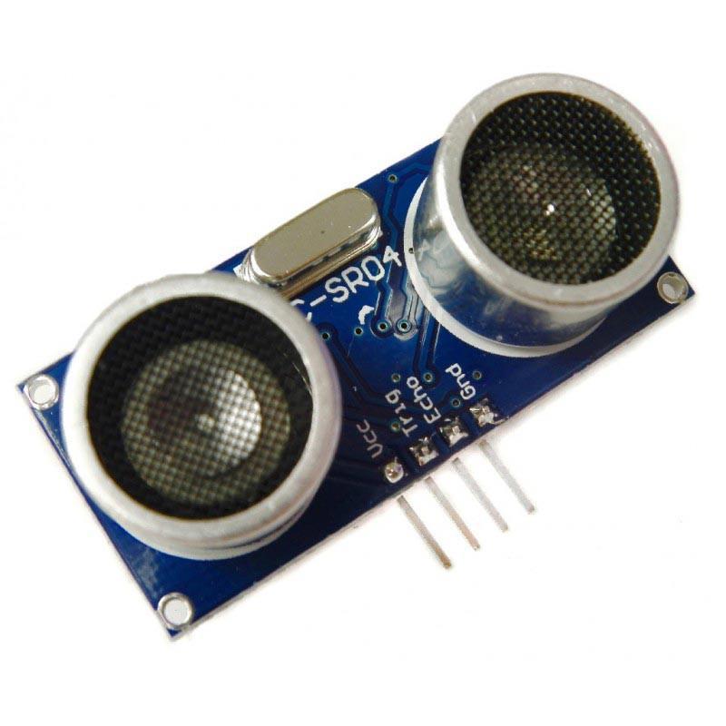
First, we need to declare the distance sensor which is:
sen = DistanceSensor(echo=8, trigger=18) #change the numbers by whatever GPIO pins for each
Know if you need to test the distance sensor there is a simple code which is:
print("Distance ", sen.distance*100)
Now for stoping the car whenever it is near something it includes a simple if statement like
def stop1():
if(sen.distance*100>5):
print(' Distance: ', sen.distance * 100)
motor_left.stop()
motor_right.stop()#you can change this up how much you want
Because this is a function we need to plug it in every single movement function for it to work.
And Now this is It
If you want to see my whole code then click on the link below