Robotic Arm
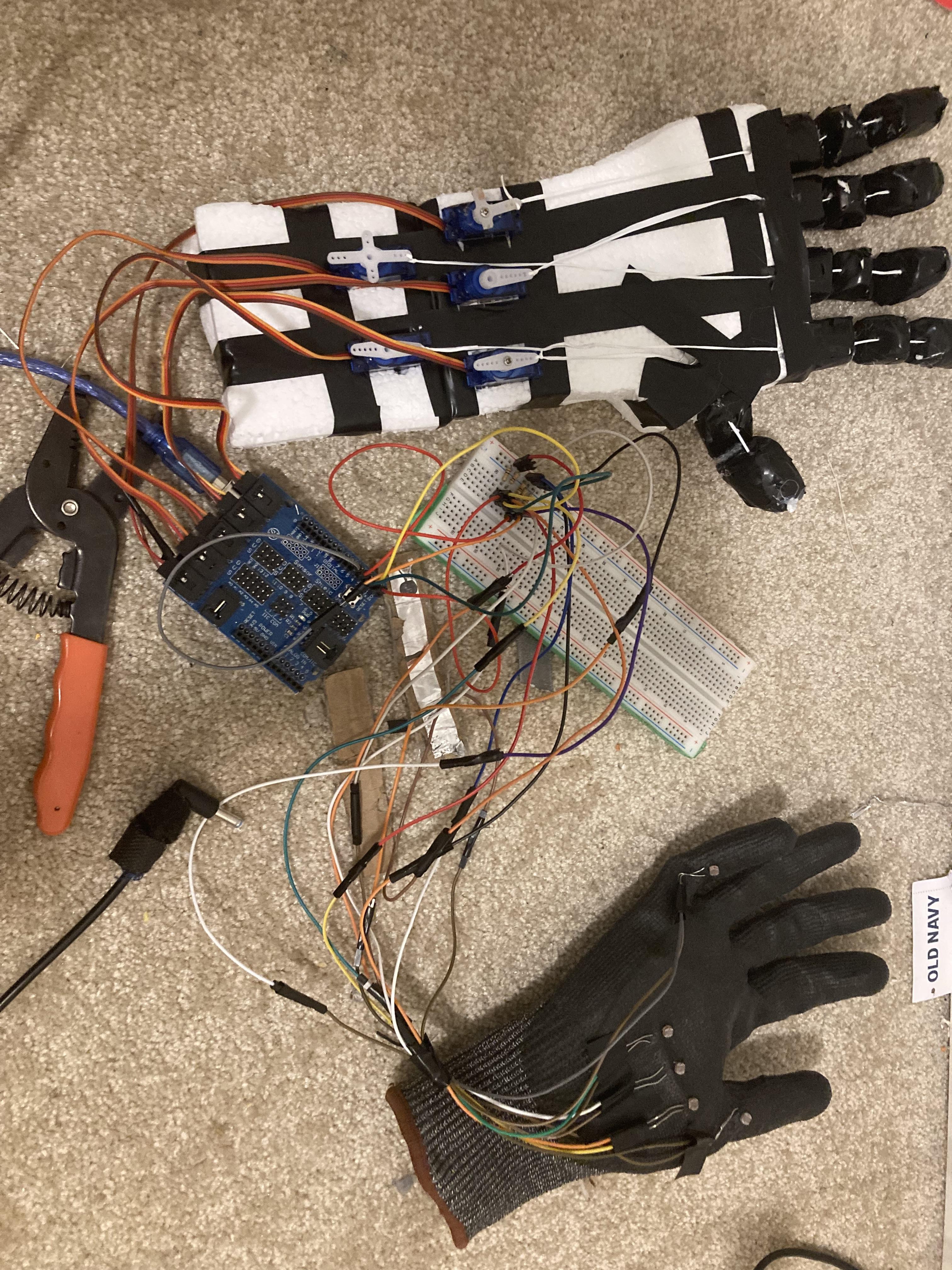
This is a robotic hand that can be controlled using your hand, and also a musical instrument. So when you touch the photo resistor, each finger bends and when you click on the push button, the green led and buzzer turns on and each time you touch the photoresistor you will get a sound from the buzzer, I coded it in a way where each photoresistors give different sounds from the buzzer.
Supplies
2 styrofoam boards
5 servo motors
5 photoresistors
1 buzzer
1 arduino
1 breadboard
1 green LED light
1 push button
5 10k ohm resistors
1 330 ohm resistor
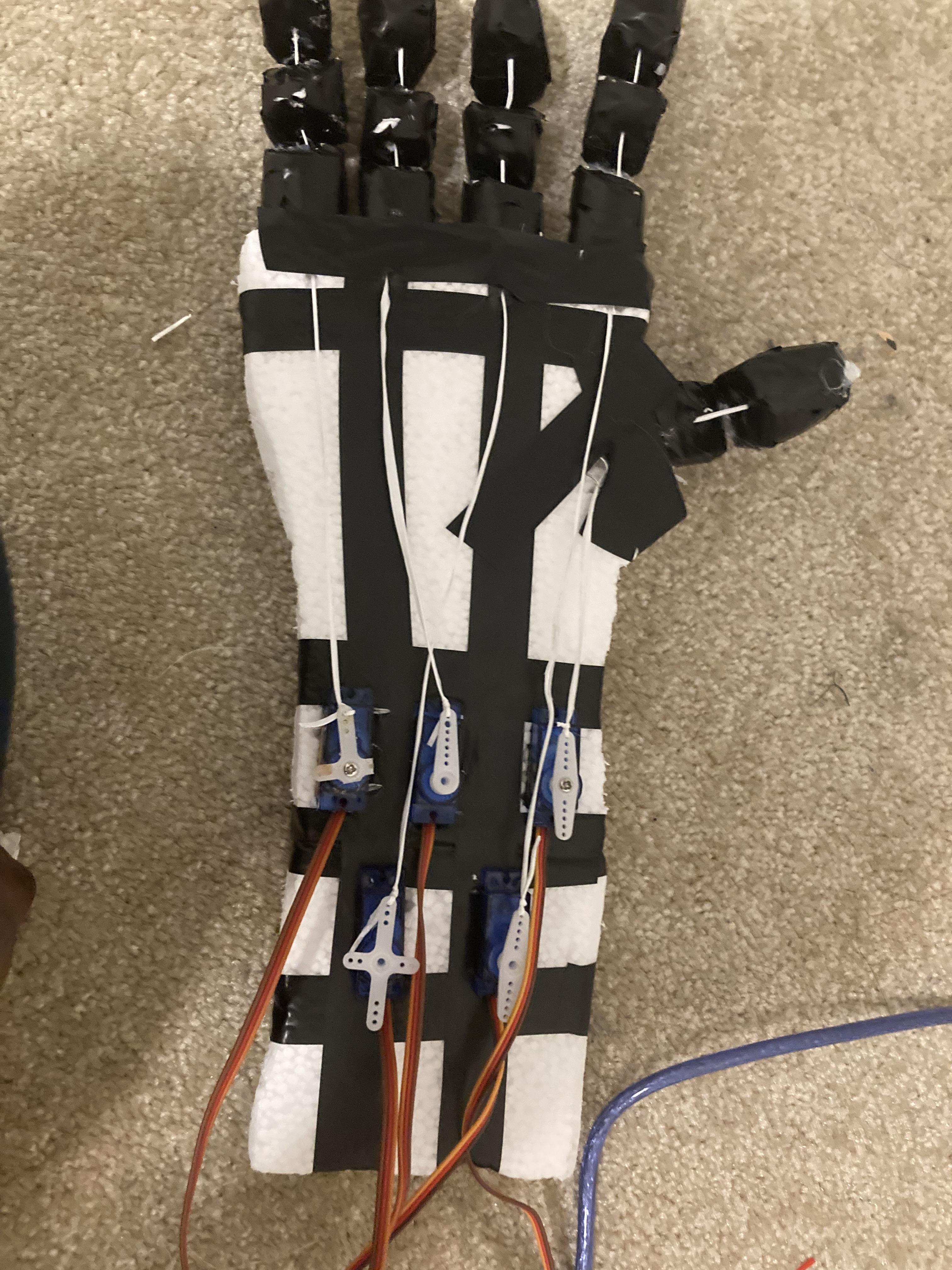
1. Take two Styrofoam boards.
2. Using one of the boards, cut out the shape of a hand.
3. After cutting out the hand shape, divide each finger into three separate sections.
4. Once the fingers are cut, create small holes in each section of the fingers.
5. Thread a string through the holes you created in each finger section.
This will help you to create more flexible, jointed fingers for the project, I purposely tried to do this project with the least materials possible because I want everyone who’s reading this to understand how to make this.
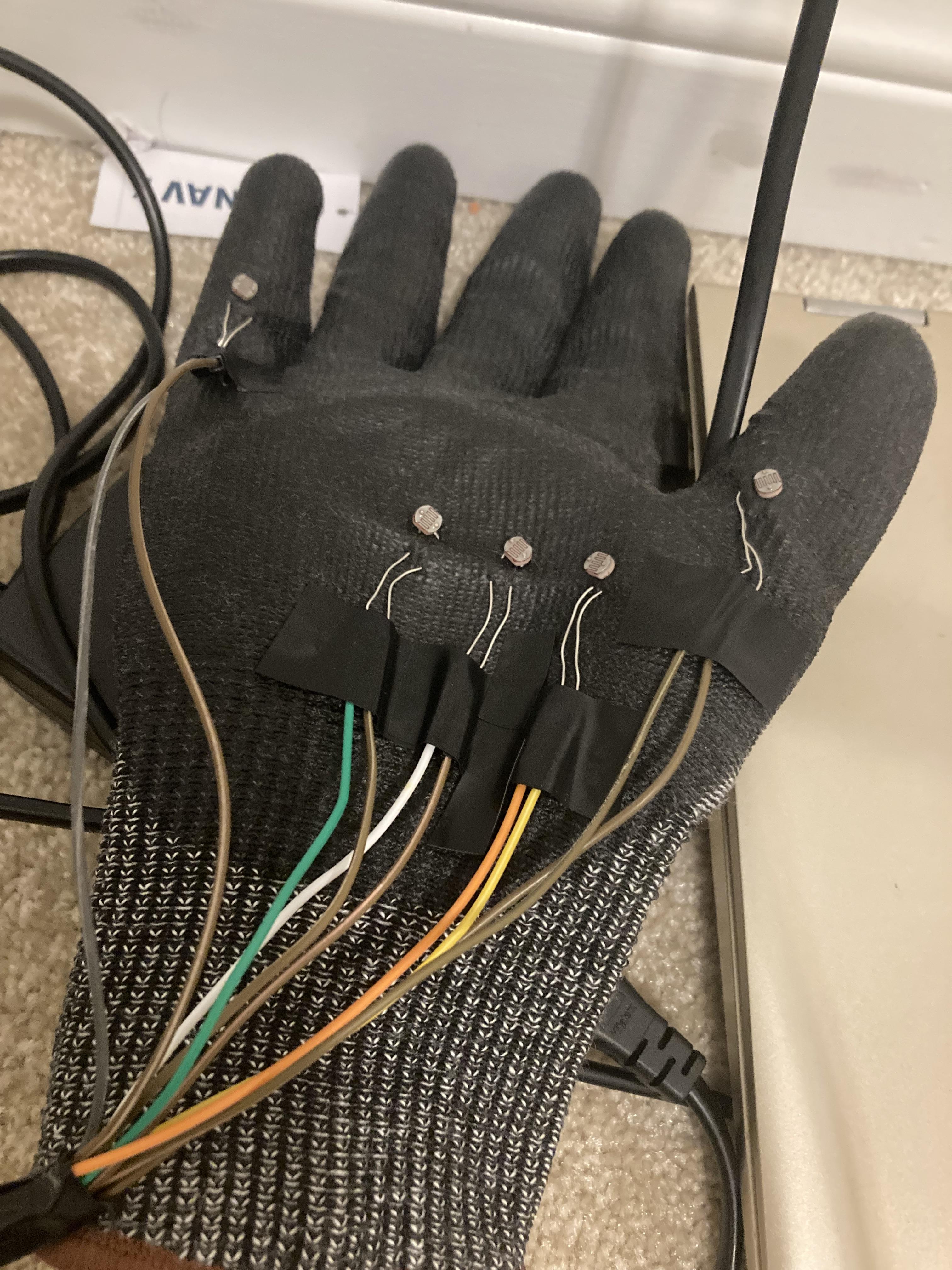
1. Purchase a glove from any dollar store.
2. Take 5 photoresistors and place one near each finger, positioning them on the palm side of the glove where your fingers bend.
3. For each photoresistor, you will need two male-to-female jumper wires, totaling 10 wires.
4. Attach the male-to-female jumper wires to each photoresistor to complete the setup.
This will allow the photoresistors to detect finger movements when you bend them.
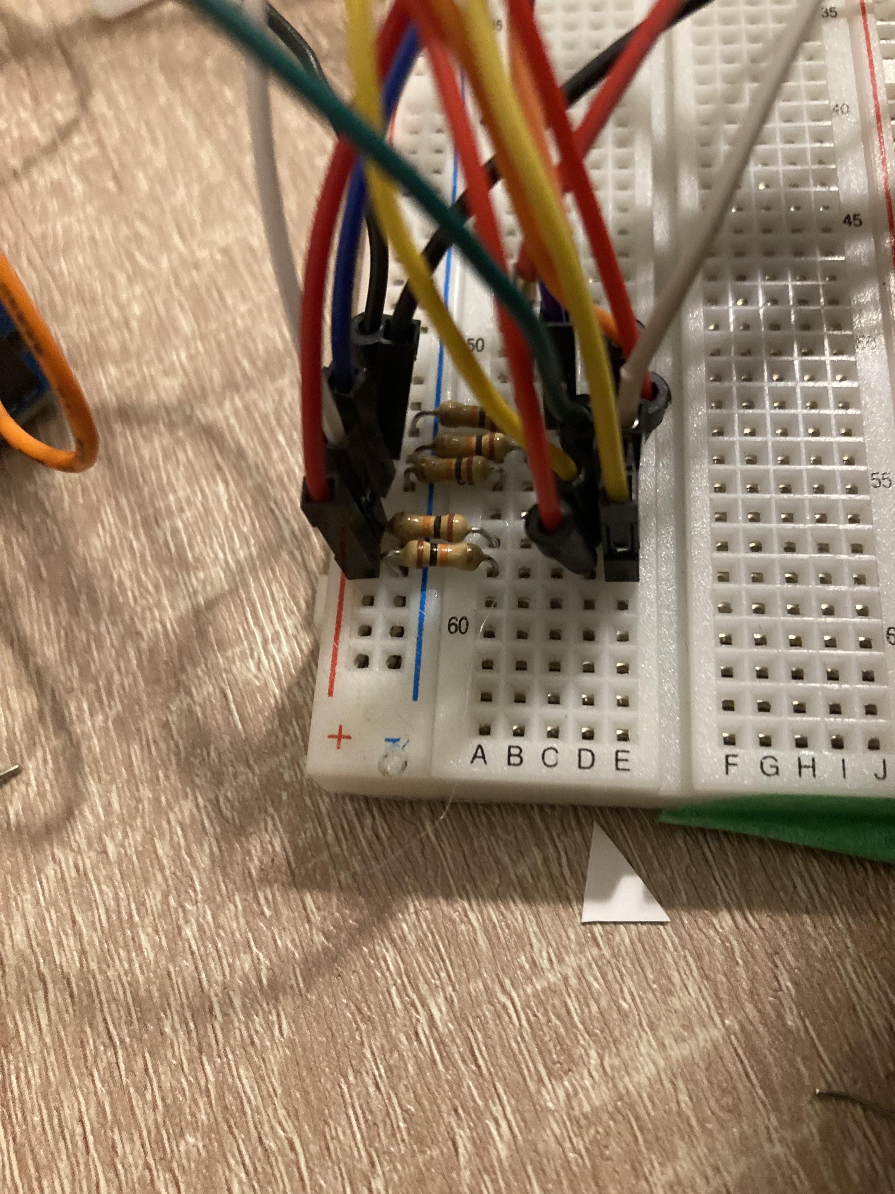
1. Take each jumper wire connected to the photoresistors.
2. Attach one wire from each photoresistor to the positive rail on the breadboard.
3. Connect the other wire from each photoresistor to the ground rail on the breadboard using a 10k resistor.
4. Now, take regular wires and your Arduino.
5. Connect the digital pins of the Arduino to each photoresistor. For this setup, you can use pins 2, 3, 4, 5, and 6 on the Arduino.
This wiring will allow your Arduino to read input from each photoresistor.
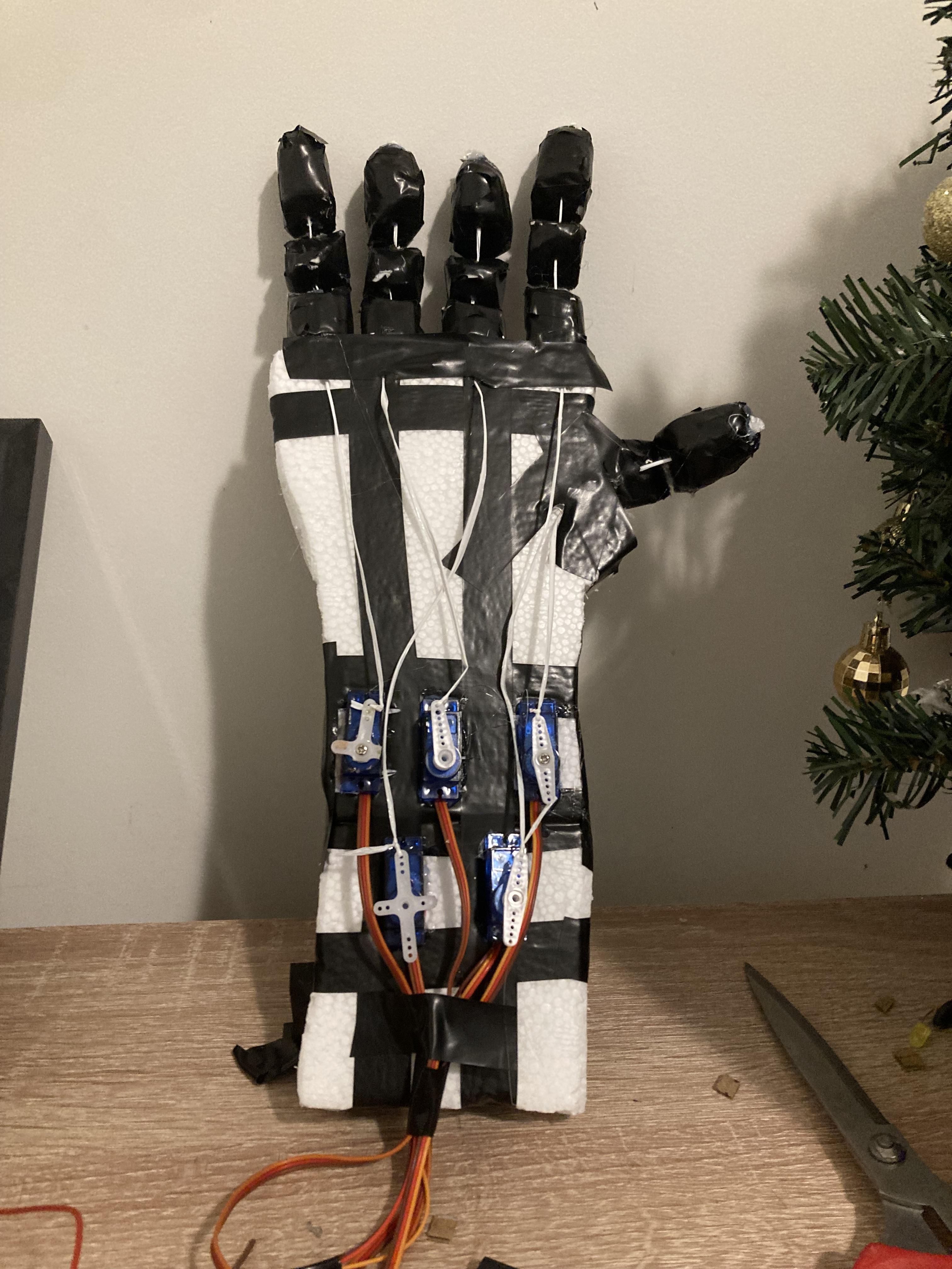
1. Take the Styrofoam arm you previously made.
2. Cut out holes at appropriate locations to fit your servo motors securely in place.
3. Once the servo motors are in position, tie the string from each finger (which you threaded earlier) to the white rotating part of the servo motor.
4. Ensure the string is tight enough so that when the servo motor rotates, it can pull the string and move the corresponding finger.
This setup will allow the servo motors to control the movement of the fingers.
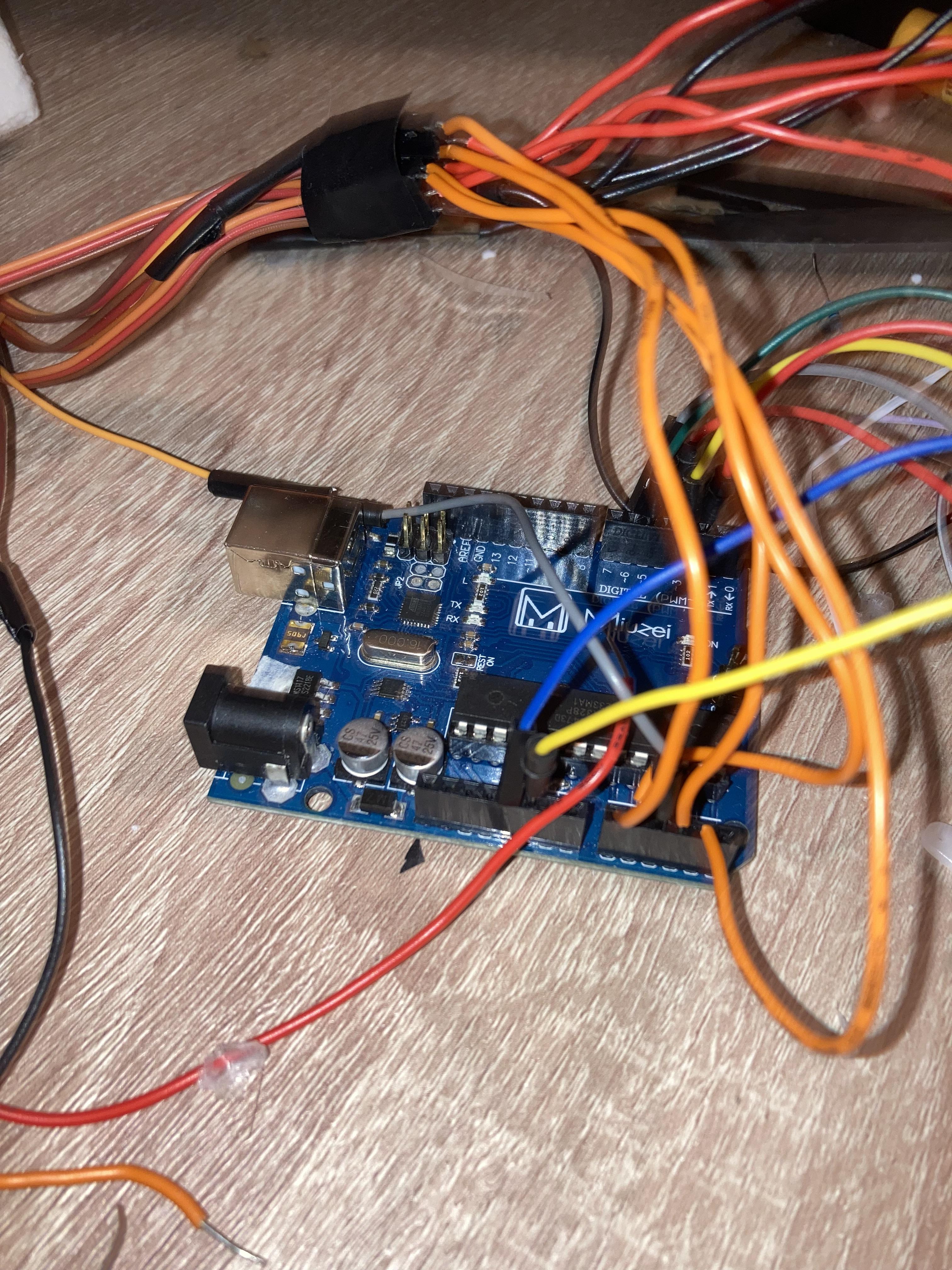
1. Take the yellow signal wire from each of your servo motors and connect them to the Arduino's analog pins A0, A1, A2, A3, and A4.
2. Next, take the red power wire from each servo motor and connect it to the positive rail of the breadboard.
3. Finally, connect the black ground wire from each servo motor to the negative rail of the breadboard.
This will supply power to the servo motors and allow control through the Arduino's analog pins.
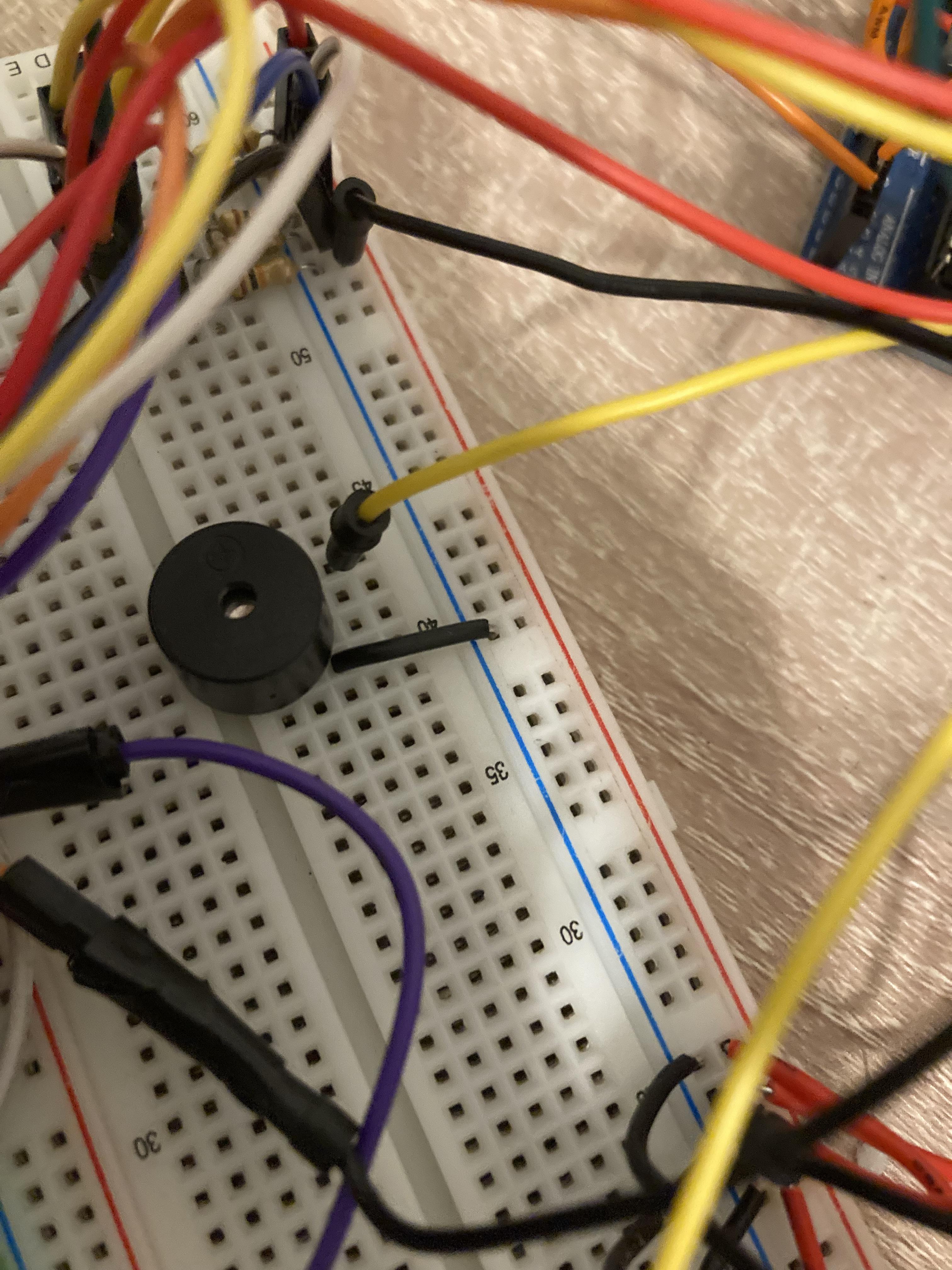
1. Take your buzzer and place it on the breadboard.
2. Connect the positive pin of the buzzer to one of the Arduino's digital pins (e.g., pin 7).
3. Connect the negative pin of the buzzer to the ground (GND) row of the breadboard, which should also be connected to the Arduino's ground.
This will allow the Arduino to control the buzzer through the designated digital pin.
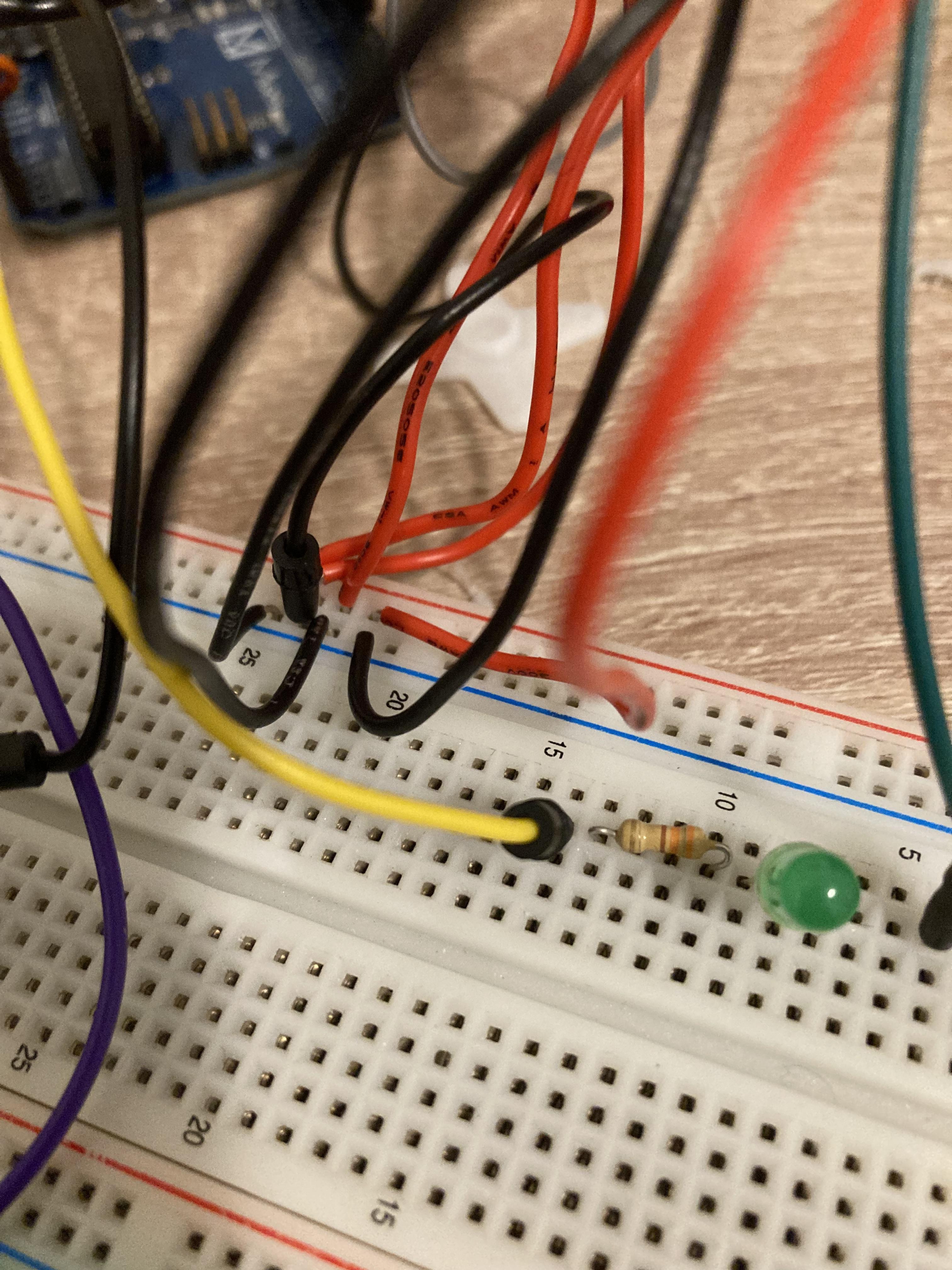
1. Place the LED on the breadboard.
2. Connect the longer leg (positive) of the LED to a resistor, and then connect the resistor to digital pin 8 on the Arduino.
3. Connect the shorter leg (negative) of the LED to the ground rail on the breadboard, which should also be connected to the Arduino's ground.
This setup will allow the Arduino to control the LED through pin 8, this part is completely uselsss and optional, I just did this beacsus I just wanted to add some random thing so I added the LED, you don’t HAVE to do this.
Take the push button and connect one leg to positive row of the breadboard, take one leg and connect it to ground row of the breadboard using 10k resistor, take another leg and connect it to PIN number 9 on the arduino
Adding the Code to the Arduino
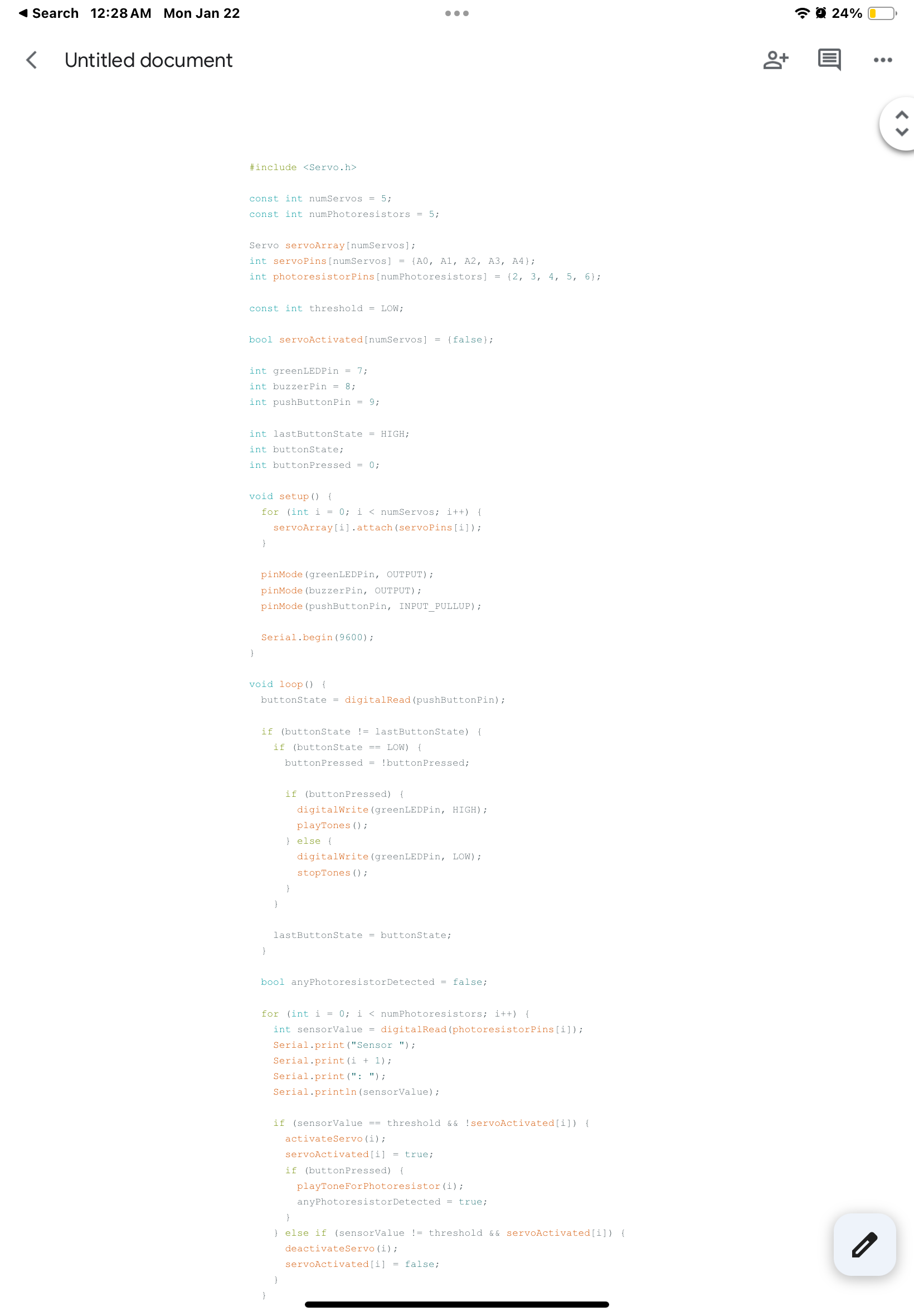
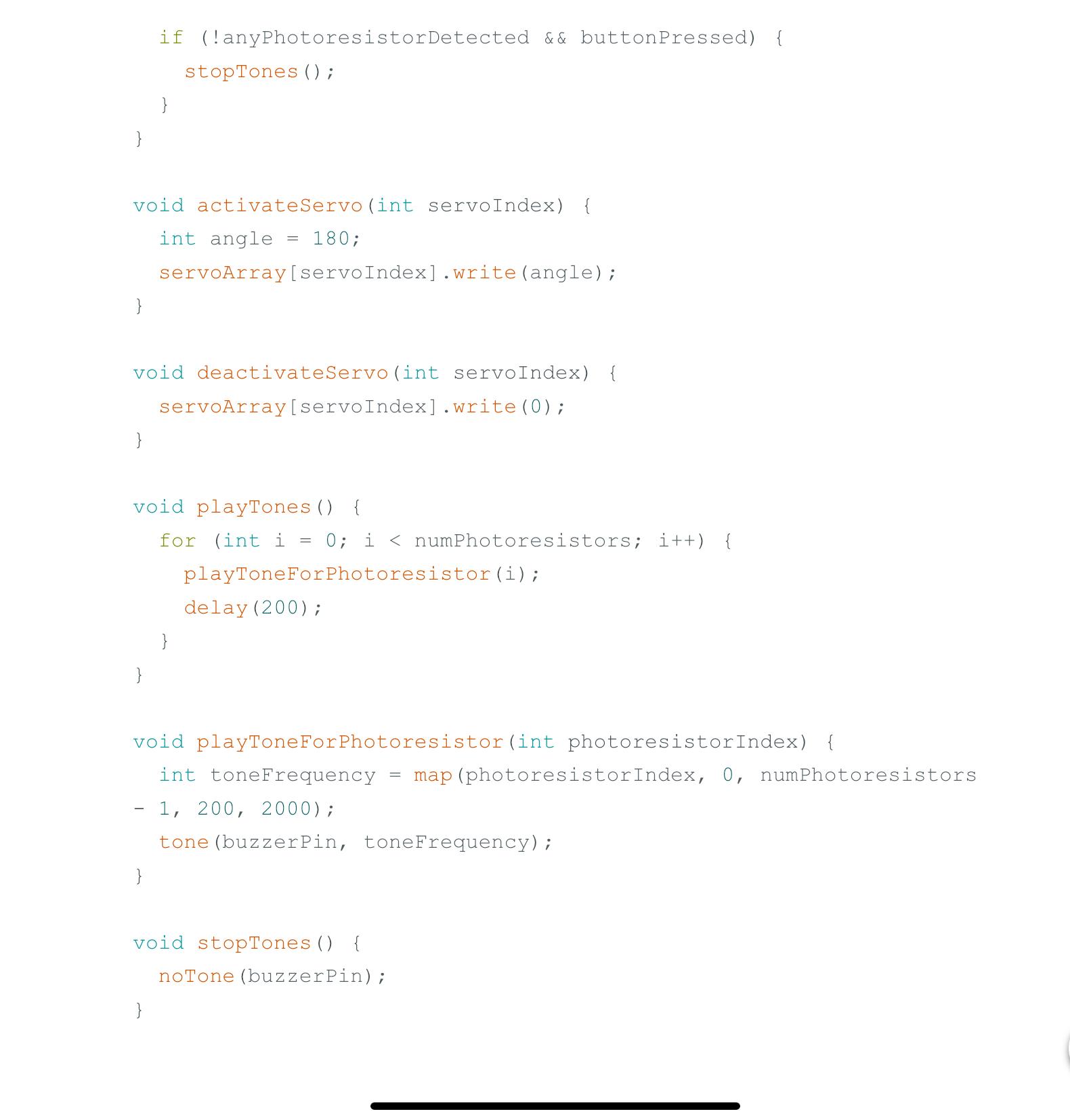
Sure! Here’s a concise explanation without bold formatting:
1. Open the Arduino IDE: Launch the software on your computer.
2. Create a new sketch: Go to File > New to start a new program.
3. Add your code: Paste your existing code into the sketch area.
4. Connect your Arduino: Use a USB cable to connect the Arduino to your computer.
5. Select board and port: Go to Tools > Board to select your Arduino model, and Tools > Port to choose the correct COM port.
6. Upload the code: Click the Upload button (right arrow icon) to upload your code to the Arduino.
7. Test your setup: Interact with the components to ensure everything functions as intended.
This will get your code running on the Arduino.