RoboRamen

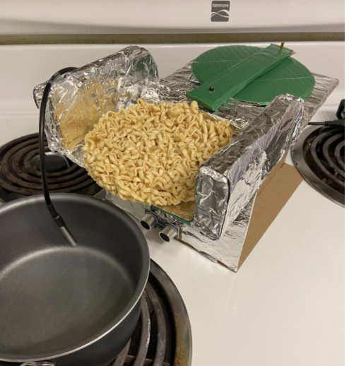
Ramen is cheap and easy, but can still be time-consuming for a busy college student. That is why I am creating RoboRamen© - a robot that can make ramen for you! All the person needs to do is get a pot of water and put the soup powder in, place the ramen noodles on the mount of the robot, and then turn on the heat. After that, the robot takes care of the rest. A temperature sensor is placed in the pot of water to determine when it reaches boiling point (about 100℃, this can be adjusted in the Arduino code to account for different altitudes). Once that temperature is reached, it will trigger a slider-crank mechanism connected to the continuous servo motor to push the ramen noodles into the pot of water. That will also trigger a timer to be set (which can also be adjusted in the code), and when the noodles are done, a tune will play from the piezo buzzer. The robot also features an ultrasonic sensor that will also trigger the piezo buzzer to beep if the robot is placed too close to the hot pot (I set a safe distance of 4 cm).
Downloads
Supplies
- Arduino Board
- USB Cable A to B
- Breadboard
- Continuous Micro Servo Motor
- Electrical Wire
- 3-Wire Extension (x2)
- Resistor, 4.7k Ohm
- Resistor, 100 Ohm
- Ultrasonic Distance Sensor
- Temperature Sensor (DS18B20)
- 3 VPiezo Buzzer
- 8.5" x 11" 22Pt Cardstock (x7)
- Aluminum Foil
- Duct Tape
- Scotch Tape
- M2 hex nut (x2)
- M2 brass, M-F, Cylindrical Standoffs (x2)
Build the Circuit for the RoboRamen©

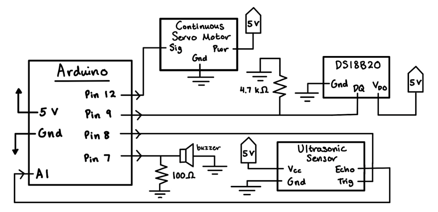
- Build the circuit according to the circuit diagram attached.
- Test the circuit with the Arduino code to ensure it is working properly before moving on to the next steps. Tape down or solder any wires that are loose. Add a 3-wire extension to the prongs of the ultrasonic sensor so it can extend to the front of the robot.
Build the Base Mount for the RoboRamen©
Refer to Appendix C, attached as a supporting file, for reference to the Figures.
- Cut out the side base walls 1 & 2, front wall, and bottom base plate out of cardboard according to the dimensions in the appendix (refer to Figures 1-4).
- Construct the base of the RoboRamen© by taking the side base walls and front base wall (refer to Figures 1-3) and super-gluing or hot gluing them to the bottom base plate (refer to Figure 4).
- Refer to Figure 5-6 for what the assembly should look like and specific measurements.
- To the front wall of the base, tape down the ultrasonic sensor so it looks like Figure 7. Add foil to cover up the wires and secure the ends of it with tape (refer to Figure 8).
- The wires of the ultrasonic sensor should go through the hole in the base front wall (refer to Figure 3).
- Place the circuit and Arduino into the base mount with the A to B USB Cable going through the hole in the base side wall (2) (refer to Figure 2). Place the continuous servo motor and the temperature sensor outside of the base mount; we will incorporate them later into the design.
- Refer to Figure 9 (the yellow highlighted circle) for what this should look like.
Downloads
Build the Slider-Crank Mechanism for the RoboRamen©
Refer to Appendix C, attached as a supporting file, for reference to the Figures.
- Cut out 10 pieces of cardboard to the dimensions of Figure 10 (the arc in the piece is purely aesthetic and can be done without measurements). Layer five of the pieces together and bound securely with duct tape, all around the piece until it is covered by duct tape. Repeat with the other 5 pieces. These are the side walls of the slider crank, which are reinforced by the multiple layers of cardboard.
- Cut out 3 pieces of cardboard to the dimensions of Figure 11. Layer the pieces together and bound securely with duct tape, all around the piece until it is covered by duct tape. This is your slider crank pusher. Poke a hole only halfway through the part as indicated in the drawing, big enough for the standoff to fit.
- Overlay this part with foil so it has a smoother contact point with the walls of the slider crank.
- Cut out 2 pieces of cardboard to the dimensions of Figure 12. Layer the pieces together and bound securely with duct tape, all around the piece until it is covered by duct tape. This is your slider crank arm.
- Poke holes near the top and bottom of the crank arm (as indicated in Figure 12) so the standoff can fit through. Make sure it isn’t too close to the edges.
- Finally, cut a single piece of cardboard to the dimensions of Figures 13-14. These are your slider crank base and wheel. Put a layer of duct tape over each piece for increased stability. Poke a hole through the slider crank wheel as shown in Figure 14 so that a standoff can fit through.
- Tape the continuous servo motor down to the bottom of the slider crank base as shown in Figure 15.
- Place and duct tape the slider crank walls down onto the slider crank base as shown in Figure 16. Make sure the slider crank pusher can move smoothly between them.
- Overlay the whole structure with foil (to make it a smoother surface so the crank can operate easily) and secure it all down. Make sure to keep a small opening for the servo motor to peek through.
- Tape the servo motor attachment to the bottom of the slider crank wheel (refer to Figure 17).
- Attach the slider crank arm to the edge of the wheel using the pre-poked holes and a standoff. Secure the male end of the standoff with a hex nut to ensure it stays together. Secure the other end of the slider crank arm to the slider crank pusher using the pre-poked holes and the standoff. Have the female end of the standoff go first so you can secure the male end (that sticks out) with a hex nut.
- Refer to Figure 18 for how the final assembly should look.
- Attach the servo motor attachment to the servo motor on the slider crank base, and adjust the slider crank pusher so it is aligned between the slider crank walls (refer to Figure 19).
Downloads
Put the RoboRamen© All Together
Place the slider crank mechanism on top of the base mount of the RoboRamen©. Tape the temperature sensor to the side of the slider crank wall, angling it specifically so it would be submerged in the water for your pot. Refer to Figures 20-21 for how the finished assembly should look!
Downloads
Operation Instructions
- Place the RoboRamen© on the stovetop, next to a pot filled with water.
- Use the A to B USB Cable to connect the Arduino board to the computer.
- Edit the RoboRamen© code to the boiling point temperature of your altitude, and the buzzer timer to the cook time of your ramen. Upload the attached code robot_code.ino.
- Adjust the position of the robot if the buzzer starts beeping (the hot pot will be too close to the robot otherwise!)
- Place the noodles on top of the mount, add your soup base and flakes into the pot, and place the temperature sensor into the pot.
- Let the robot do its thing, walk away, and get some work done!
- The buzzer will play a tune and your ramen is all ready. Enjoy!