Retro TV With Raspberry Pi
by Democracity in Circuits > Raspberry Pi
9592 Views, 44 Favorites, 0 Comments
Retro TV With Raspberry Pi
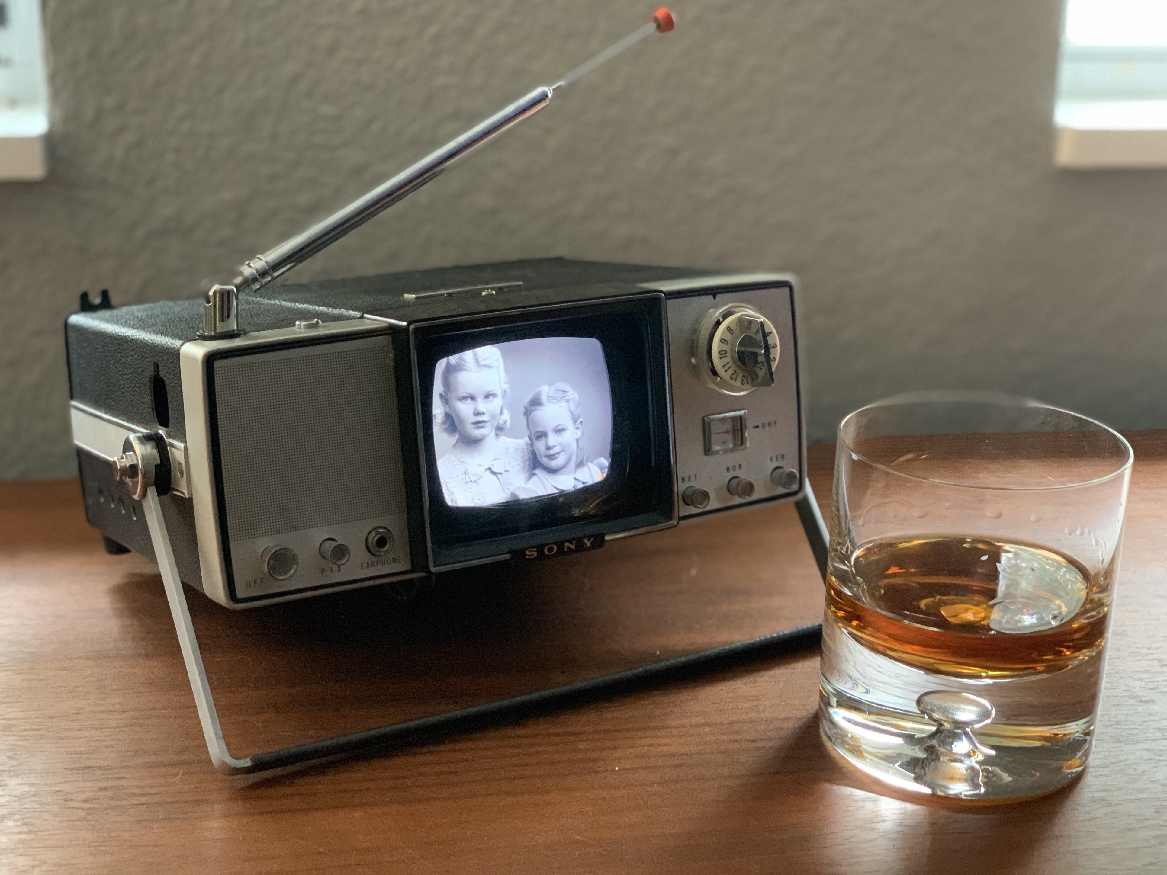
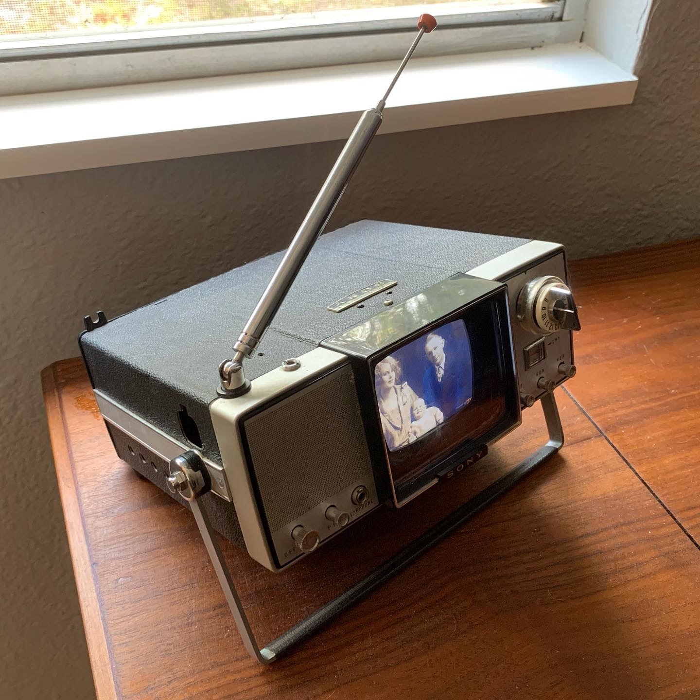
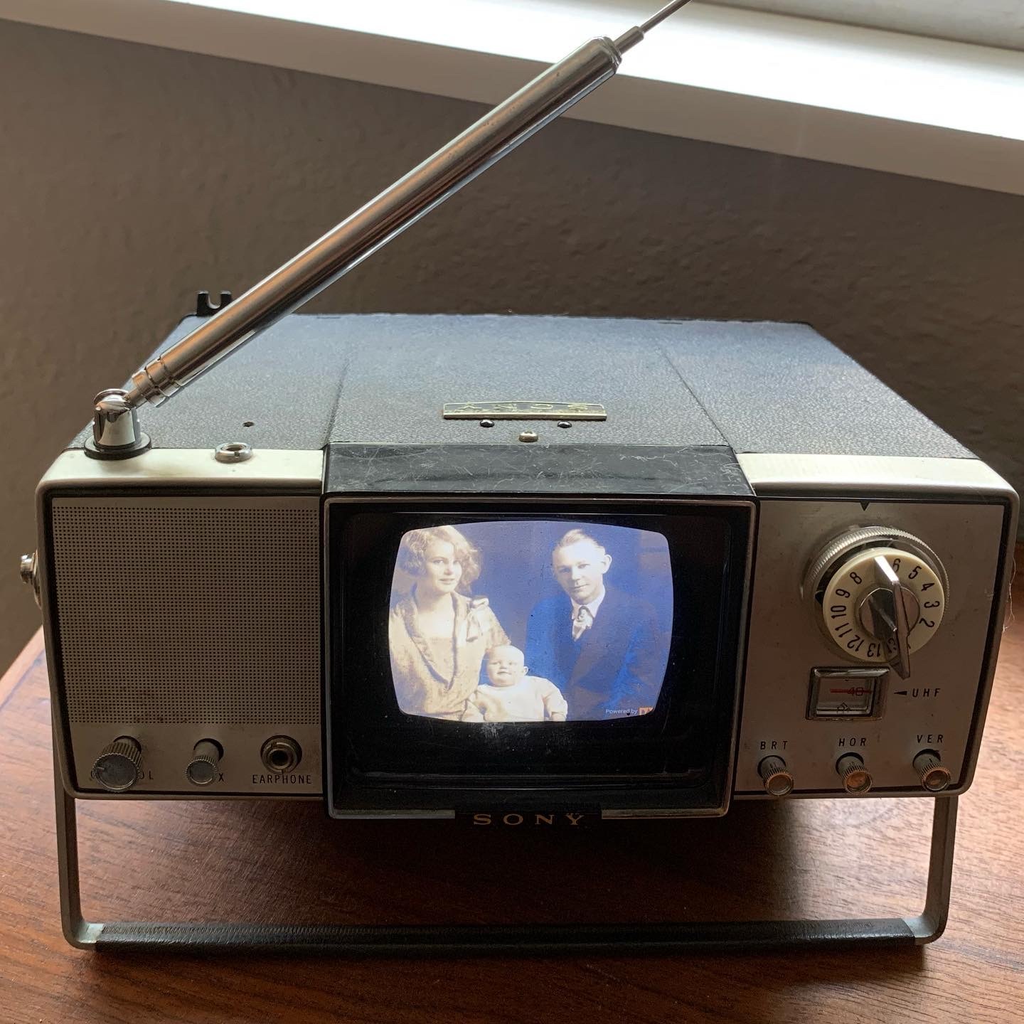
Always fascinated with the design aesthetics of retro electronics, I wanted to also bring in some updated tech to maximize its capabilities. With that being said, the goal was to take a cool-looking Sony Micro TV (model: TV4-203uw) from the mid 1960's and turn it into a digital photo frame featuring vintage family photos.
Perhaps the most difficult part, is finding a combination of vintage television, with their 4:3 aspect ration screen, that will work with modern 16:9 LCD screen. You may get lucky and find a television that has the correct size for the limited number of available 4:3 LCD screens, but I wanted something a bit more compact to sit on a shelf.
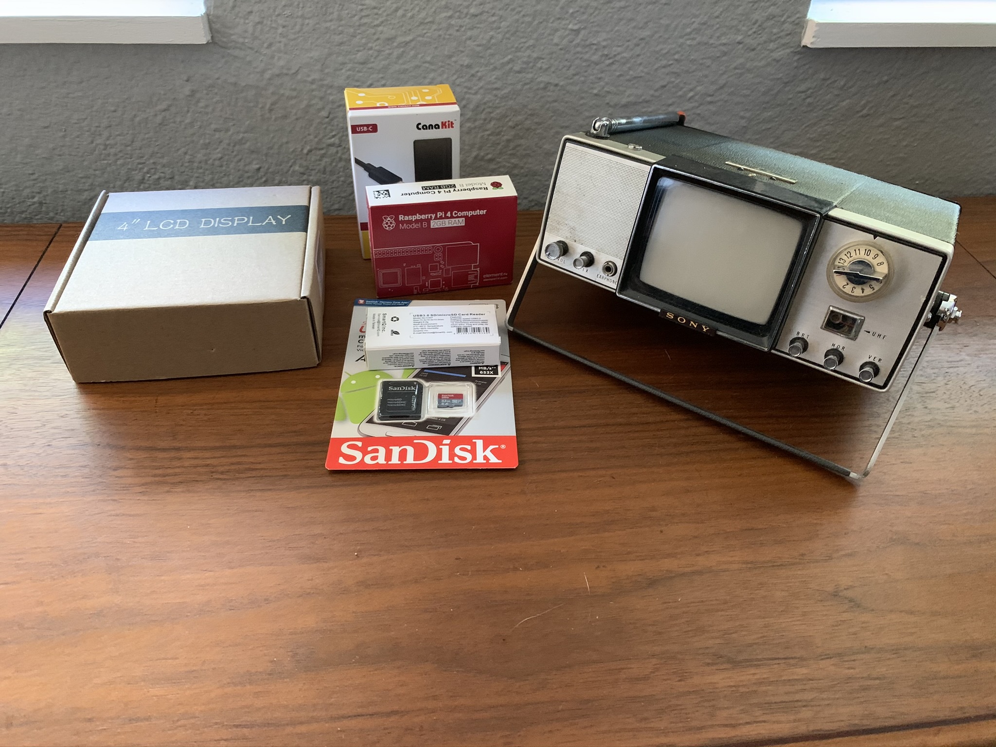
Here's what we'll need:
Supplies
The Tech:
- Vintage Television
- Raspberry Pi 4
- TFT LCD Screen
- R-Pi USB-C Power Supply (At least 3 Amps)
- Micro SD Card
- USB Micro SD Card Reader
The Consumables:
- Hot Glue or Epoxy (your preference)
- 1/16" Black Acrylic Sheet (Optional for Bezel, Substitute Black Card Stock/Paper)
- Black Foamcore
- Electrical Tape
The Tools:
- Mini Screwdrivers
- Needle Nose Pliers
- X-Acto Knife
- Drill with Various Twist Bits (for Metal)
- CNC Cutter (Optional for Bezel, Substitute X-Acto Knife)
Raspberry Pi Build
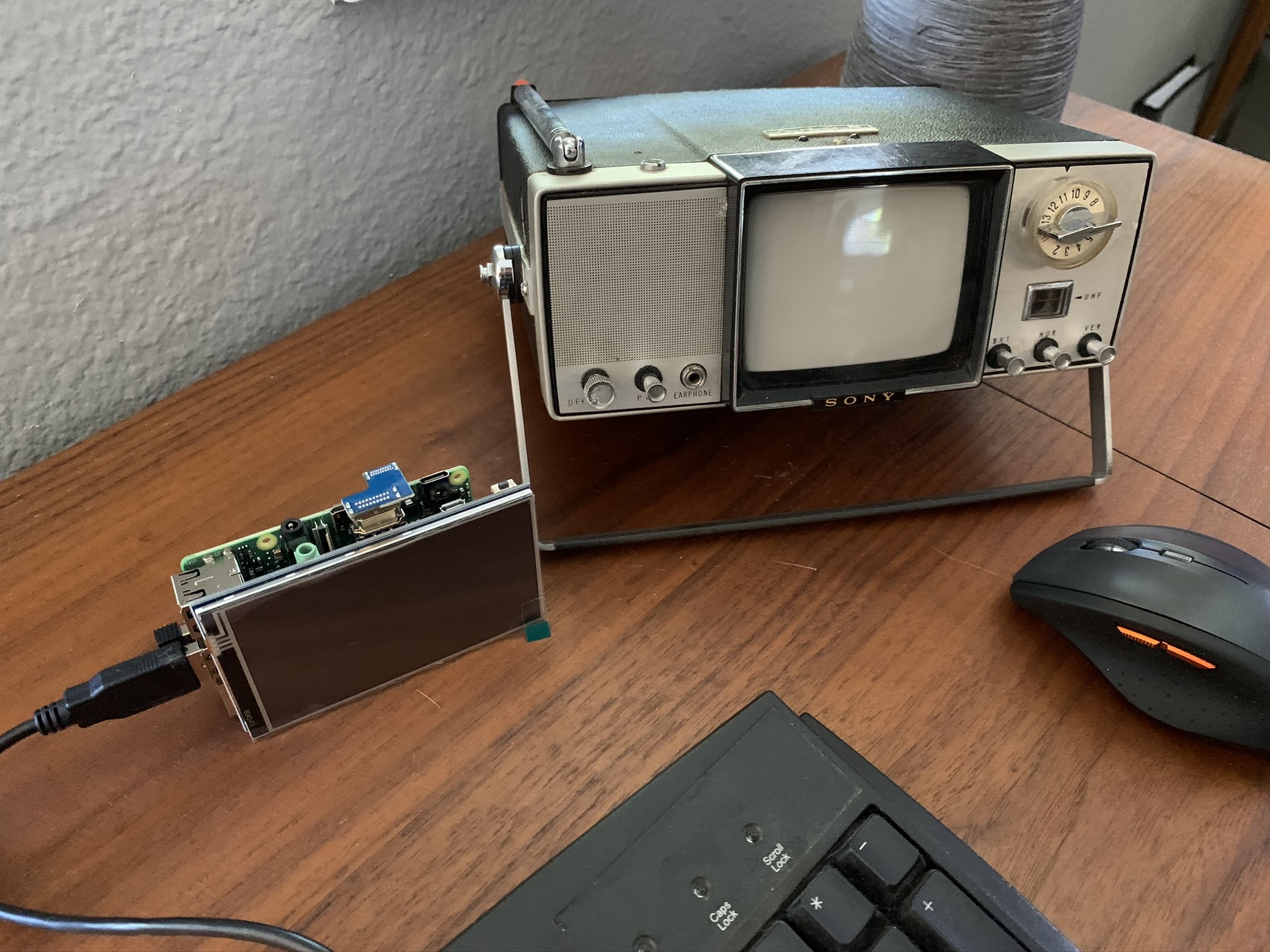
First things first, let's set up the Raspberry Pi 4:
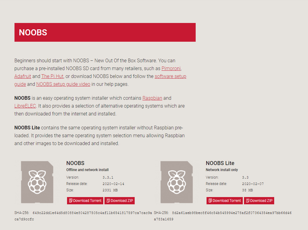
The folks at Raspberry Pi have put together a great guide for downloading and installing their operating system. We'll be using their simplest version: Noobs
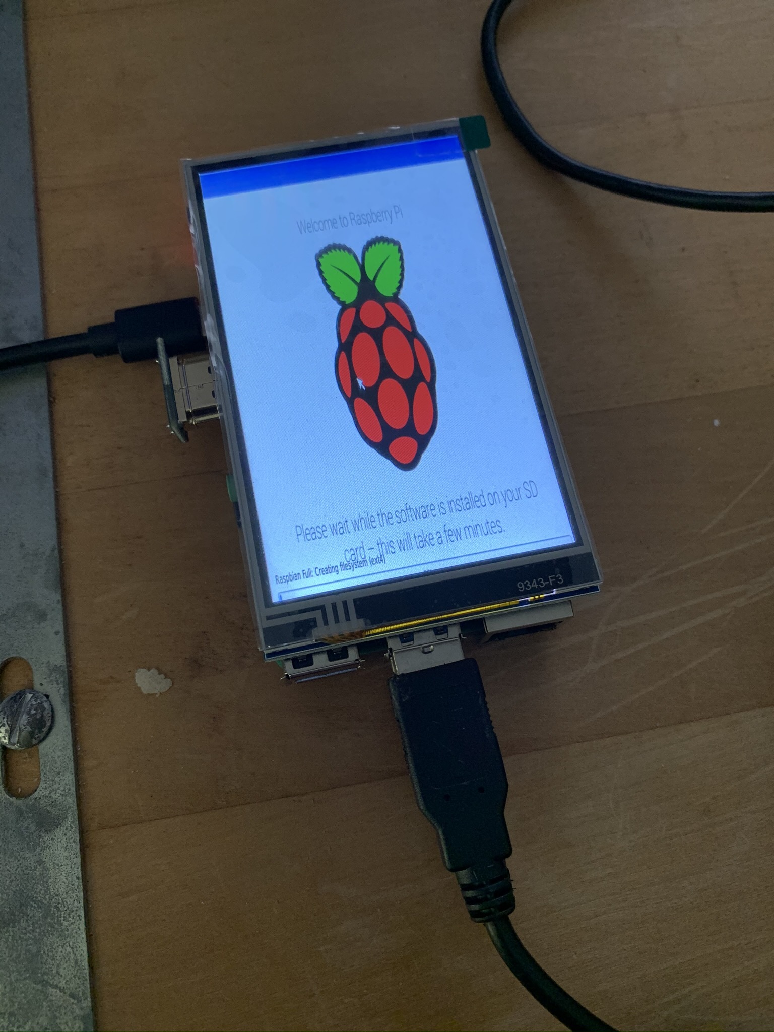
Once the SD card is prepped and ready, plug into your R-Pi:
- The wireless dongle for the keyboard/trackpadMicro
- SD Card
- LCD screenFor the one I used, it plugs directly into the Extended 40-Pin GPIO Header and comes with a small cooling fan and has a u-shaped bridge to connect the HDMI
- Finally, the USB-C power cableHopefully, everything is booting once the power is plugged in. If so, follow the on-screen instructions to set up the basic functionality (password (user, wifi, etc.).
Programming
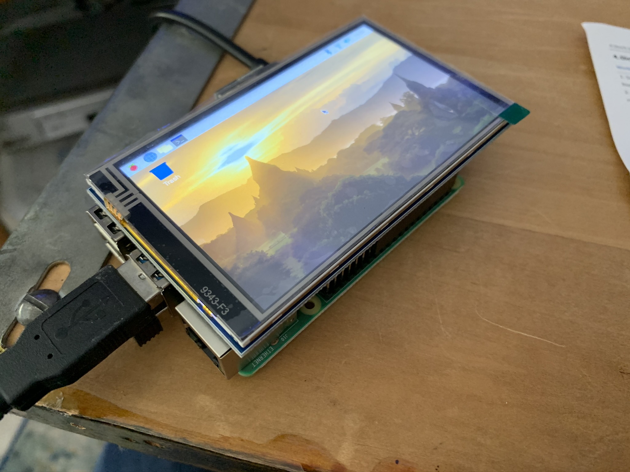
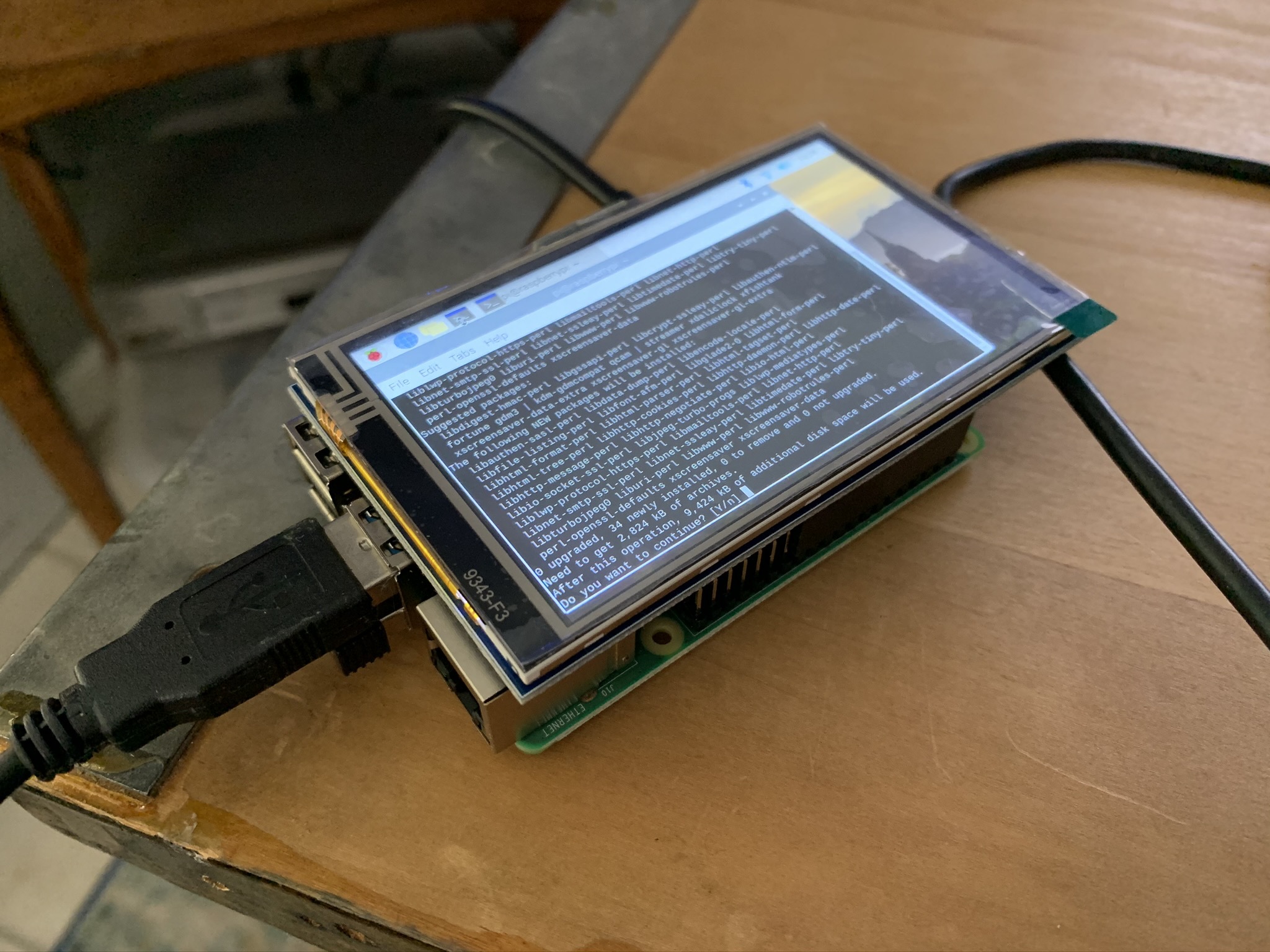
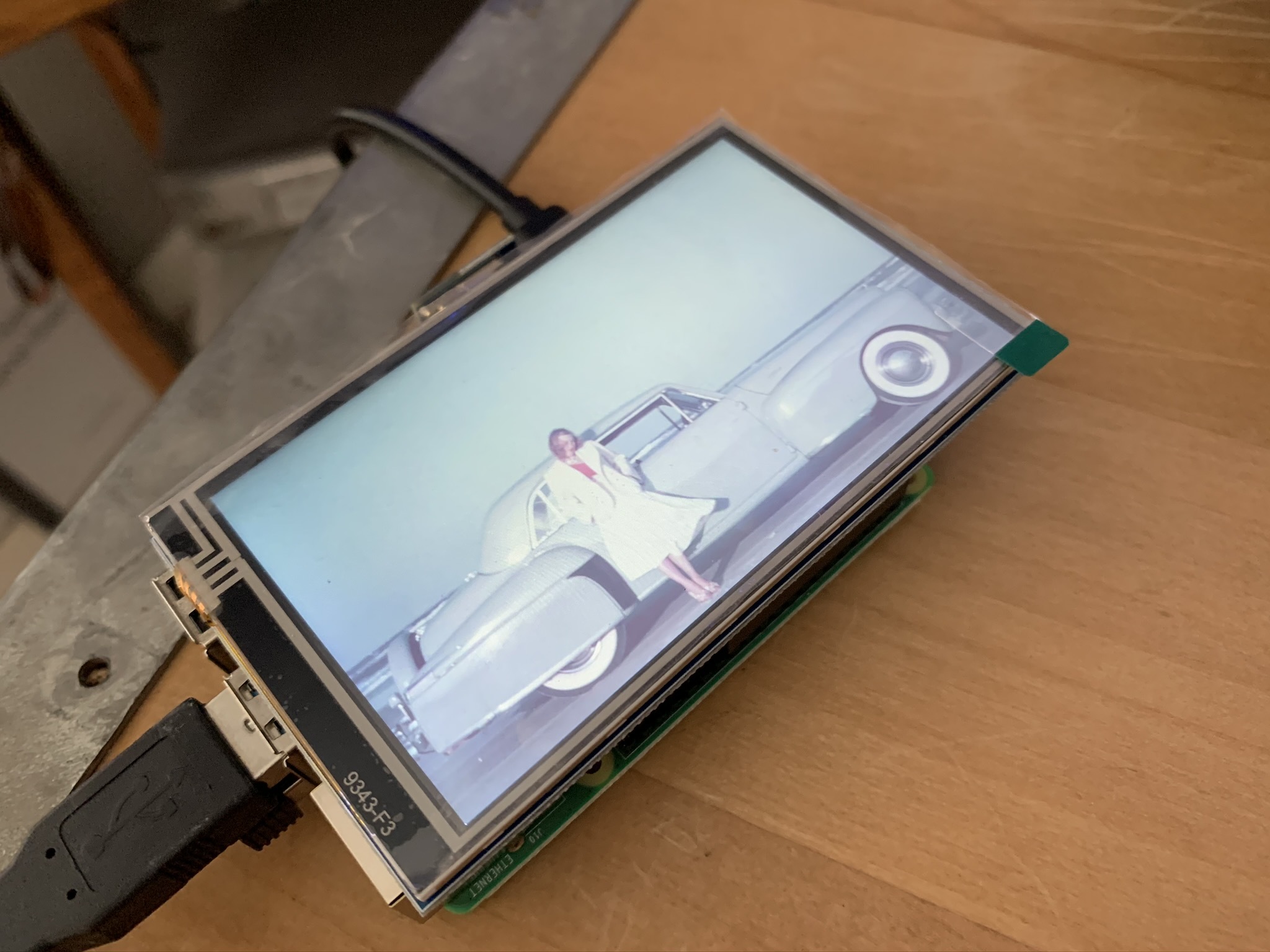
Now we get to the programming - fair warning, I used a handful of different tutorials to get this to work, which may or may not bring you success. If you get stuck, Google is your friend...
- First we'll make sure we install any updates and install our web browser, Chromium. Open up a terminal and type:
sudo apt-get update
sudo apt-get install chromium-browser --yes
- For the specific screen in the supplies, we first need to install the drivers:
sudo rm -rf LCD-show
git clone  https://github.com/goodtft/LCD-show.gitchmod -R 755 LCD-show cd LCD-show/
Then Rotate the Screen:
sudo ./MPI4008-show 180
- Open terminal and type:
sudo nano /etc/xdg/lxsession/LXDE-pi/autostart
- Then make sure your autostart contains these lines:
@lxpanel --profile LXDE-pi
@pcmanfm --desktop --profile LXDE-pi point-rpi@xset s off
@xset -dpms
@xset s noblank
@sed -i 's/"exited_cleanly": false/"exited_cleanly": true/' ~/.config/chromium/Default/Preferences
@chromium-browser --noerrdialogs --kiosk https://dakboard.com/app/screenPredefined
Now, our goal is to have the browser open on startup full screen on a specific page. For this, I used Dakboard.com since it's an easy (and free) way to add a slideshow (linked to my google drive for easy updating of images). They have a paid version for increased capabilities if you want to go that route.
- The last bit will open up our browser on our default DakBoard screen. Just make sure you log in and save password. Also couldn't help setting it as the default homepage.
Deconstructing
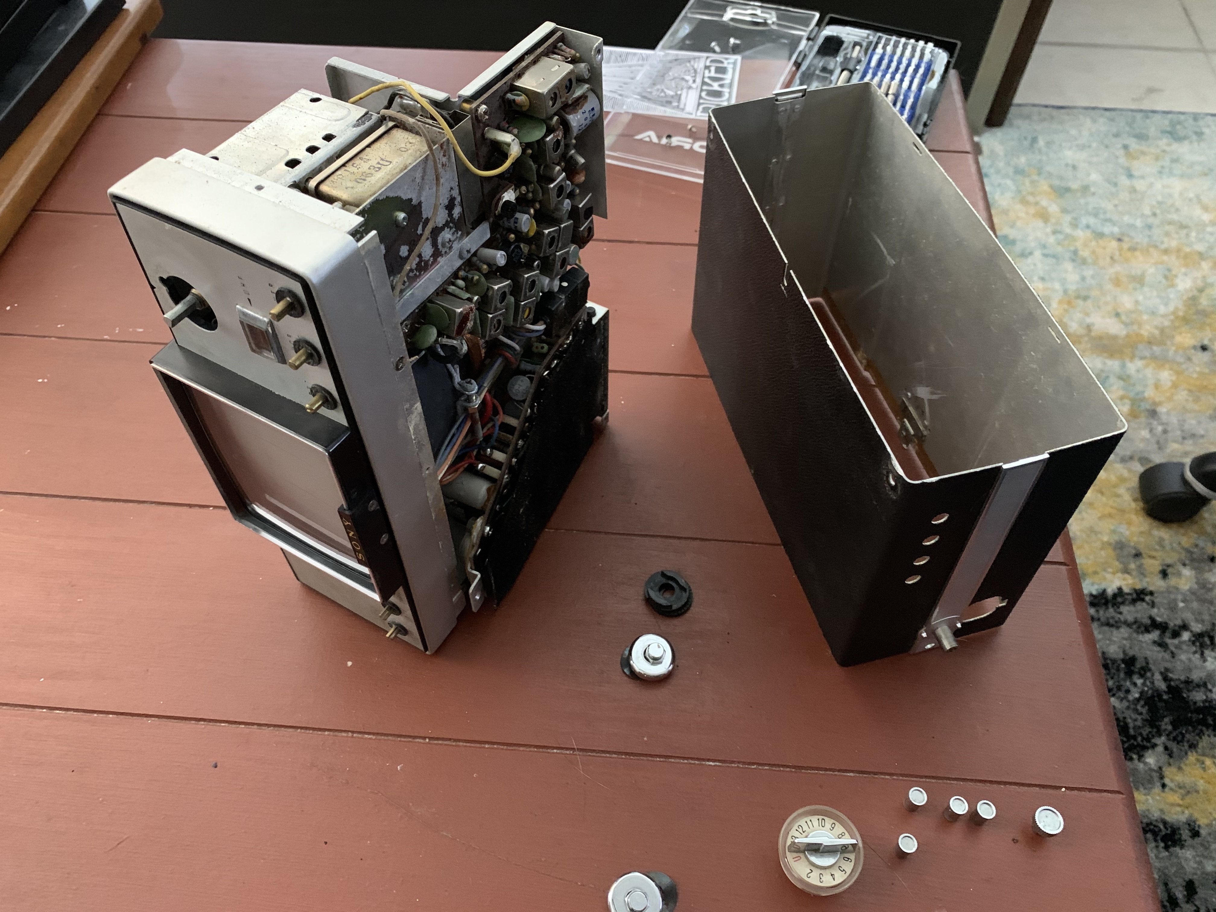
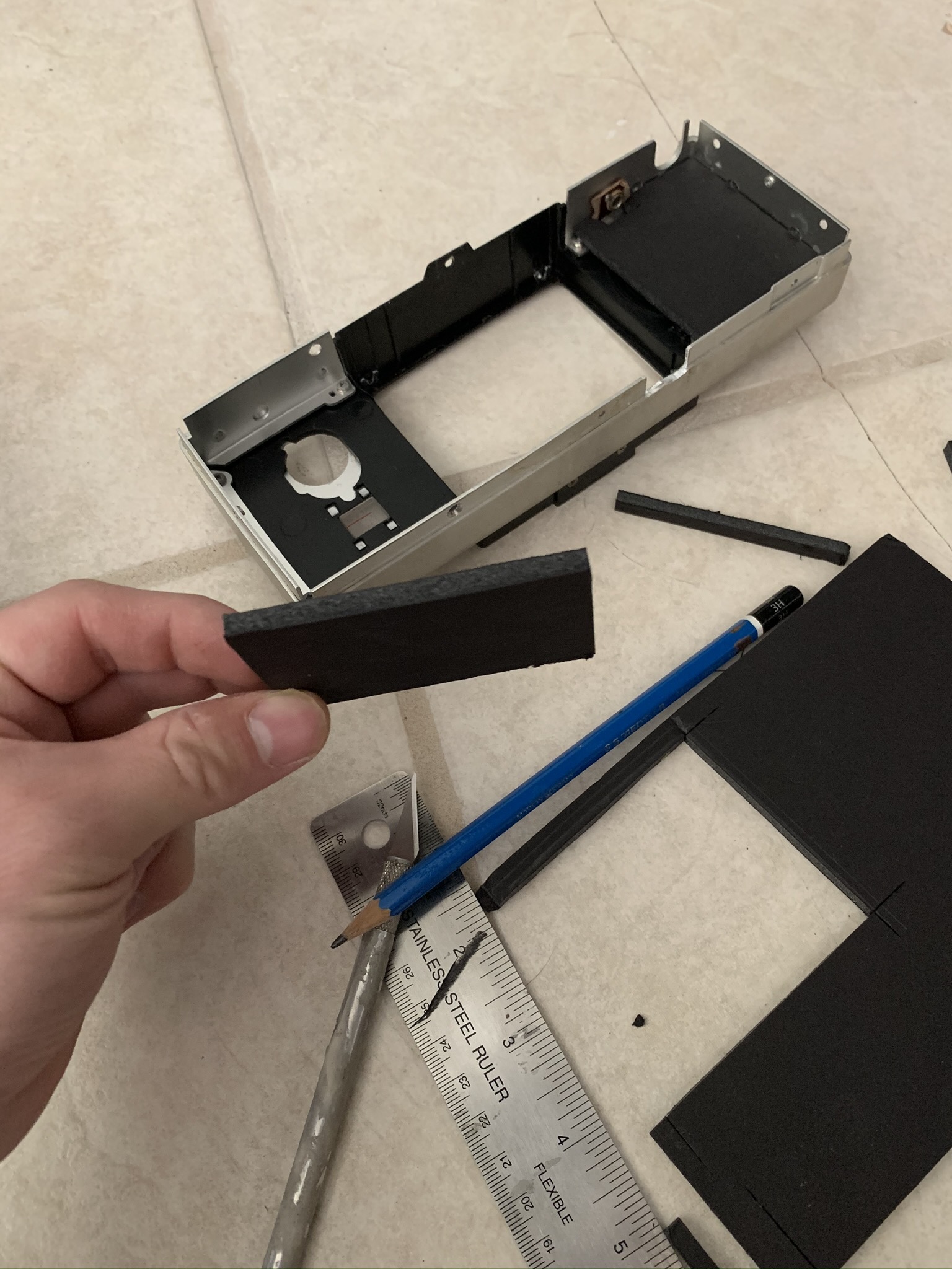
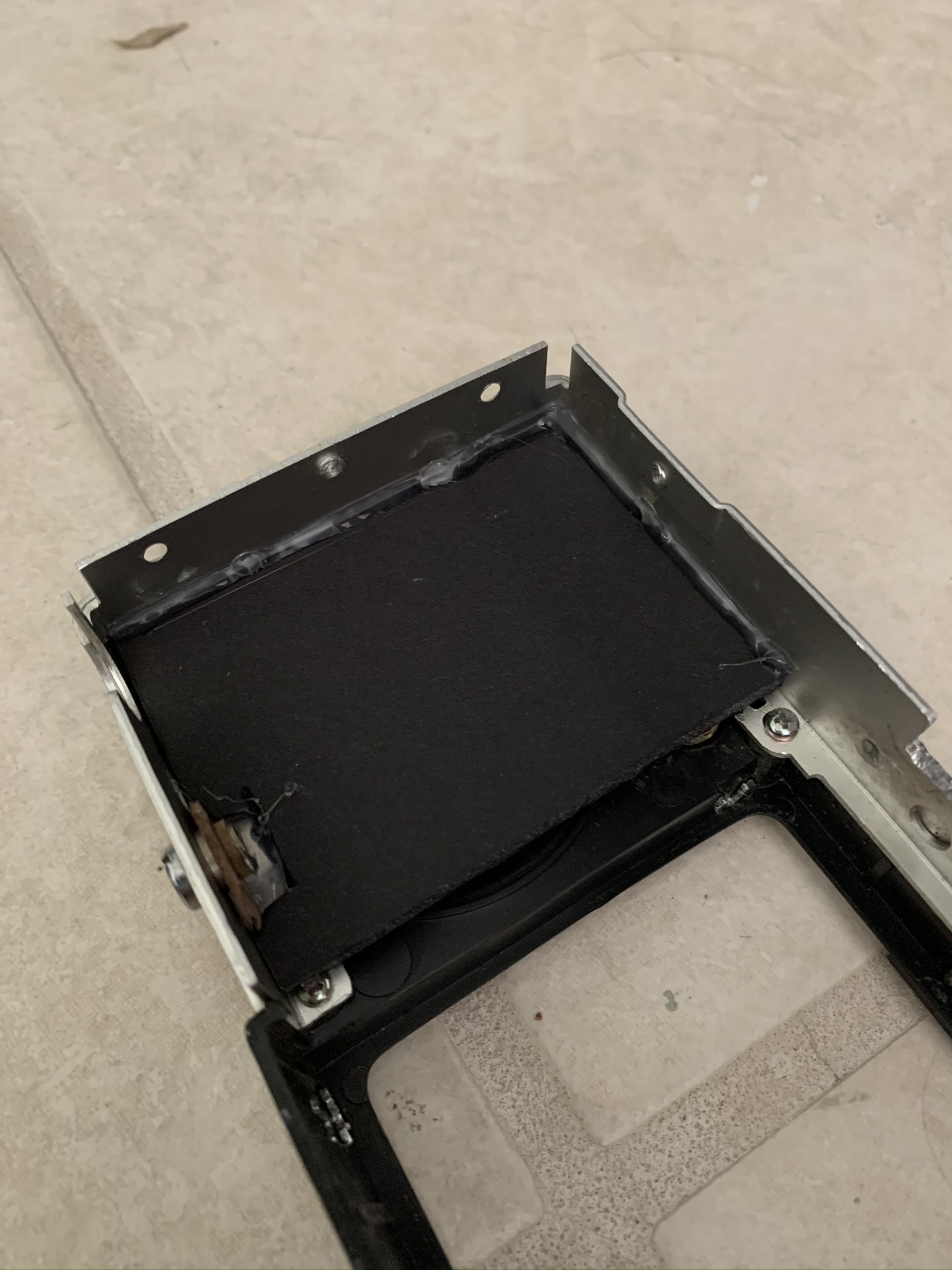
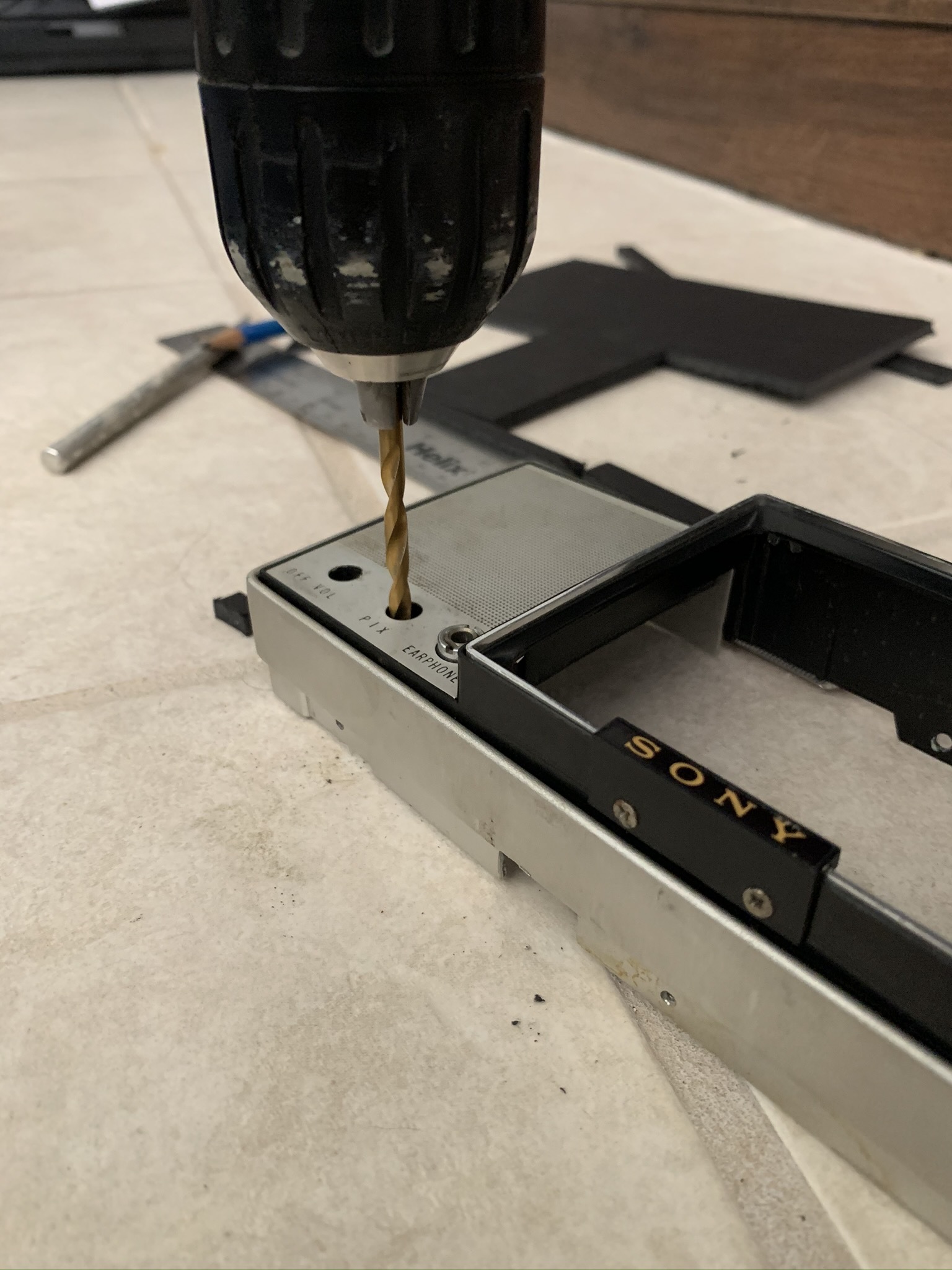
Now that the software part is complete, let's get our hands dirty!
- We'll start by removing all of the screws in the case and chassis. But first...
WARNING: Tube TVs can carry a huge charge if they have been plugged in recently. It's up to you fully ground any stored charges safely.
- We're going to keep very little of the existing components. For our purposes, we'll only want to keep those pieces and parts that are visible, namely the knobs, buttons, dials, and antenna. We'll also keep the internal parts of these so that we can still spin the knobs and press the buttons to our hearts content.
TIP: To keep all your fasteners and loose pieces in order, Adam Savage has a great tip on laying them out on a felt mat in order. I personally do the same, but with disposable plastic cups, but a great way to keep things organised (skip to 2:50):
With the housing now empty, we'll start filling in the areas that sit behind the knobs with some pieces of black foamcore. This gives us relatively sturdy mounting surface for the components and the black color helps it to blend in a bit.
- With the foamcore either hot glued or epoxied in place, we'll drill or punch out holes the diameter of the shafts for each one of the knobs to poke through.
Reconstructing
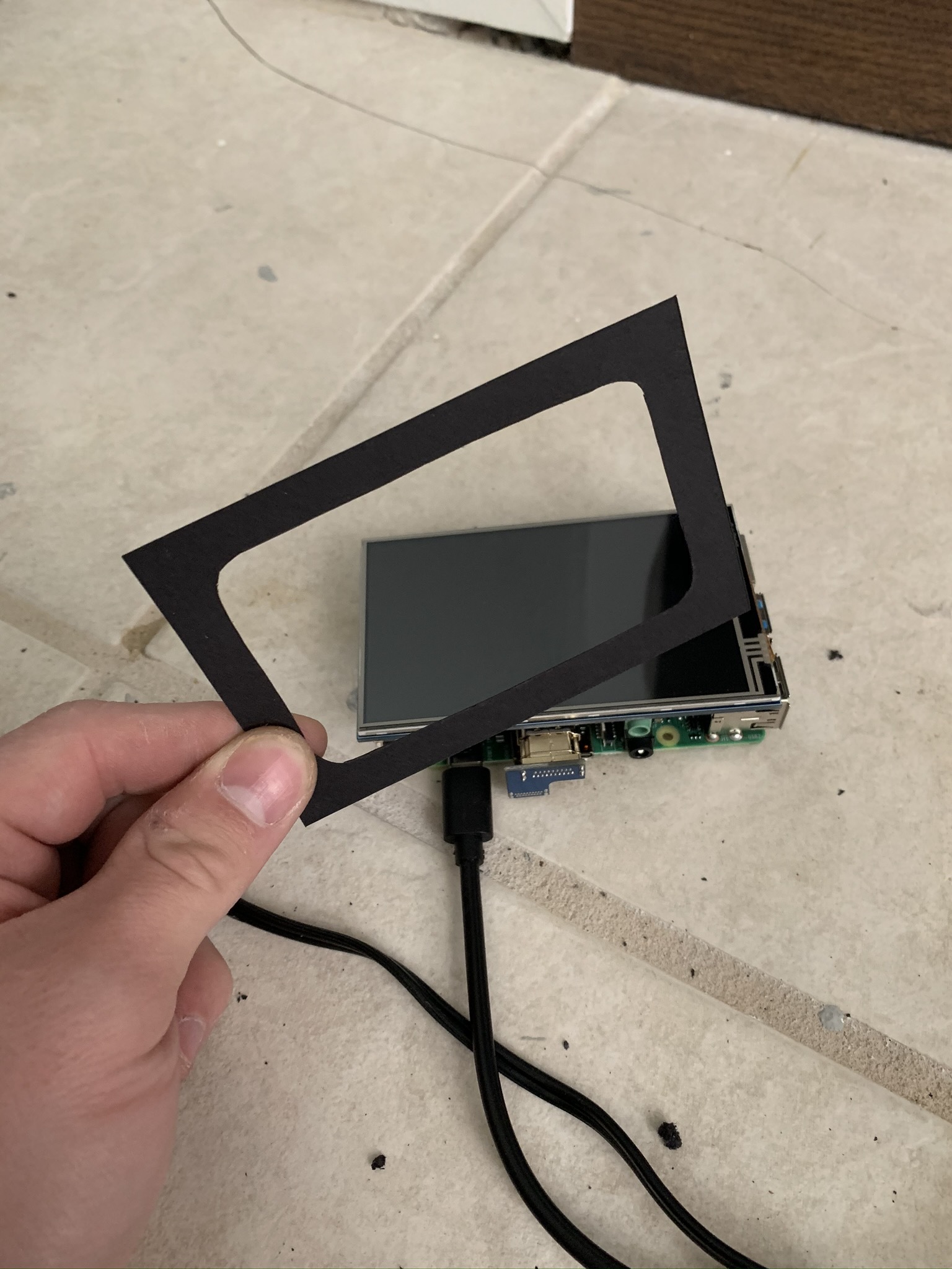
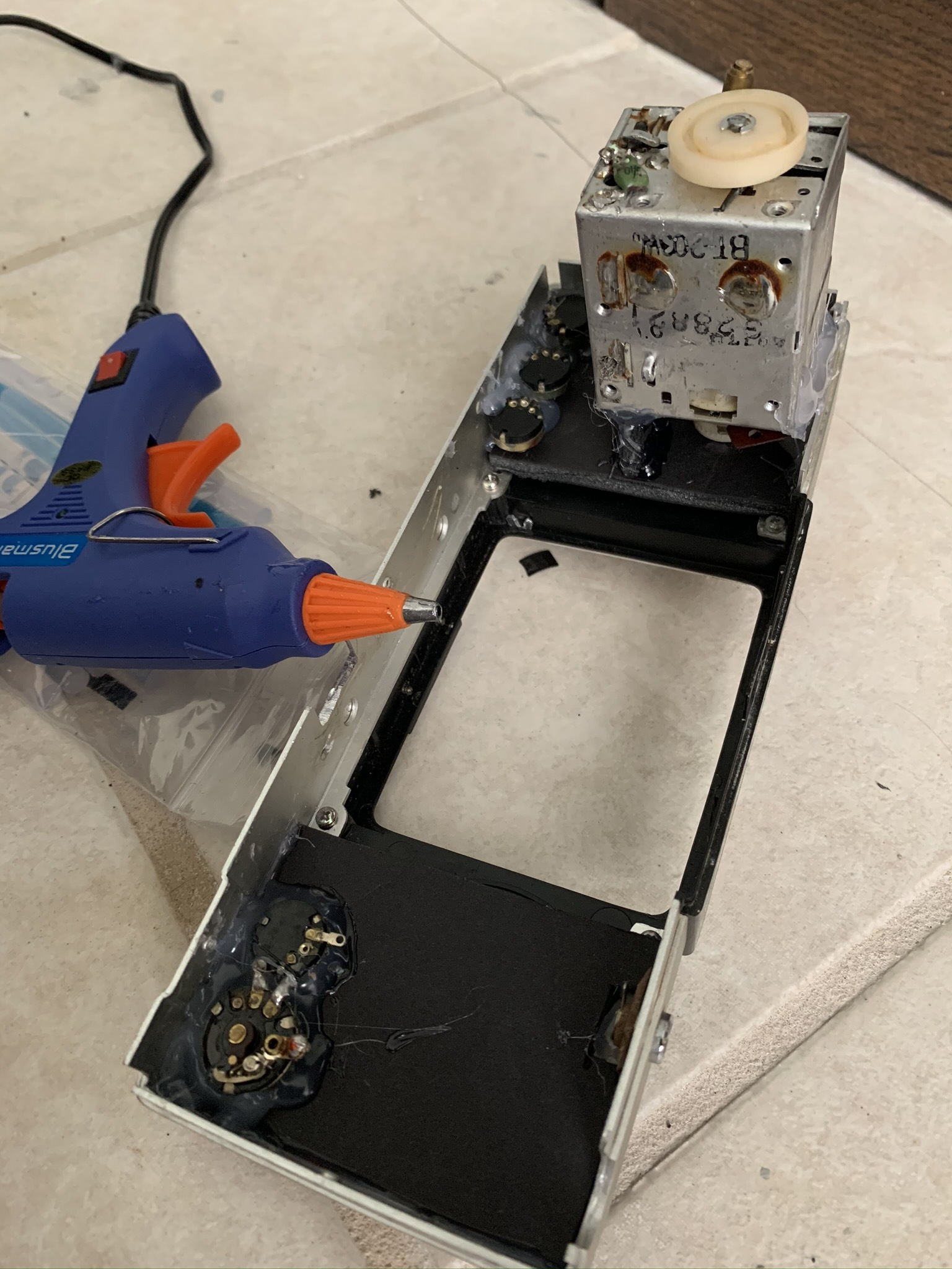
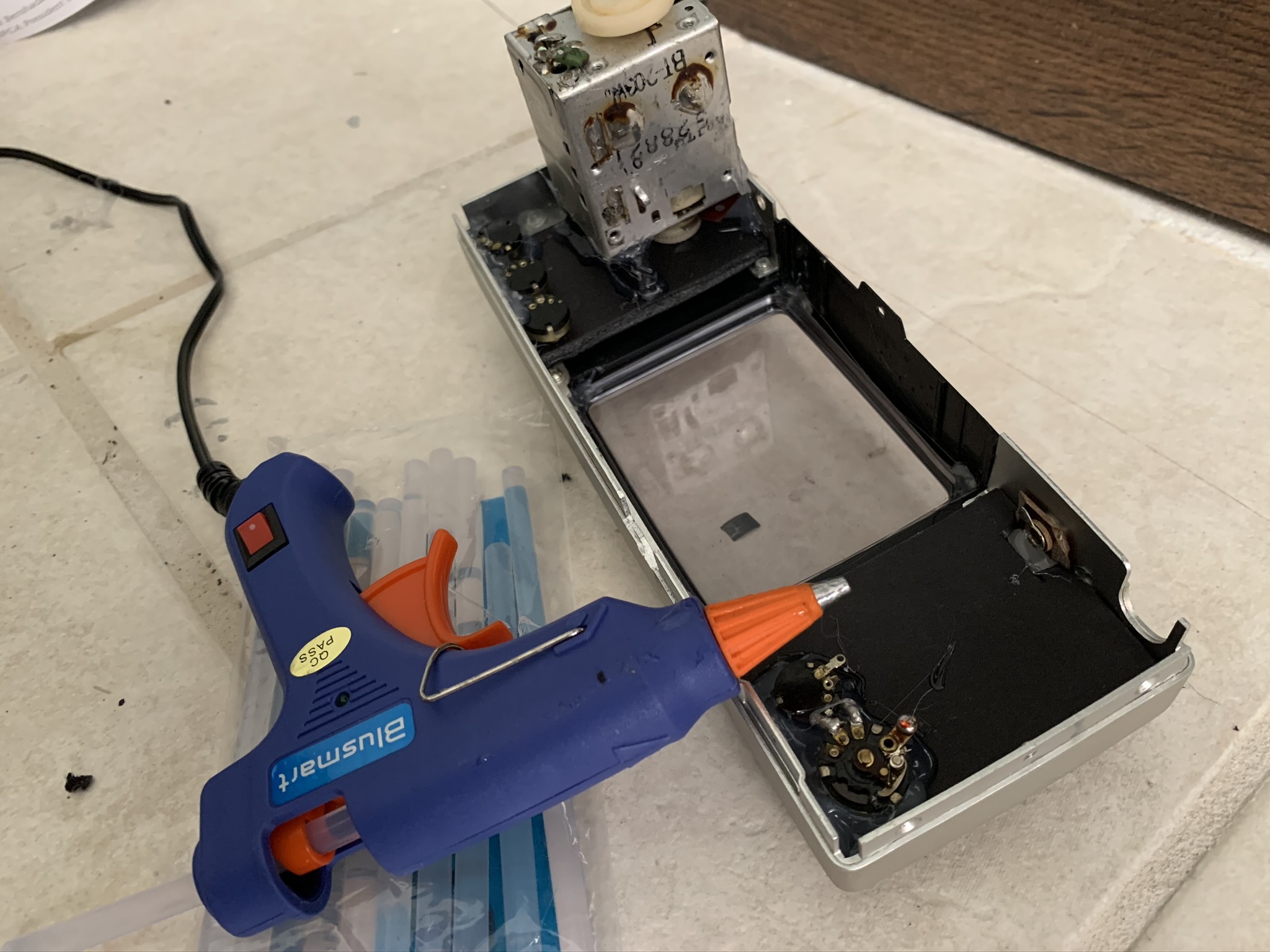
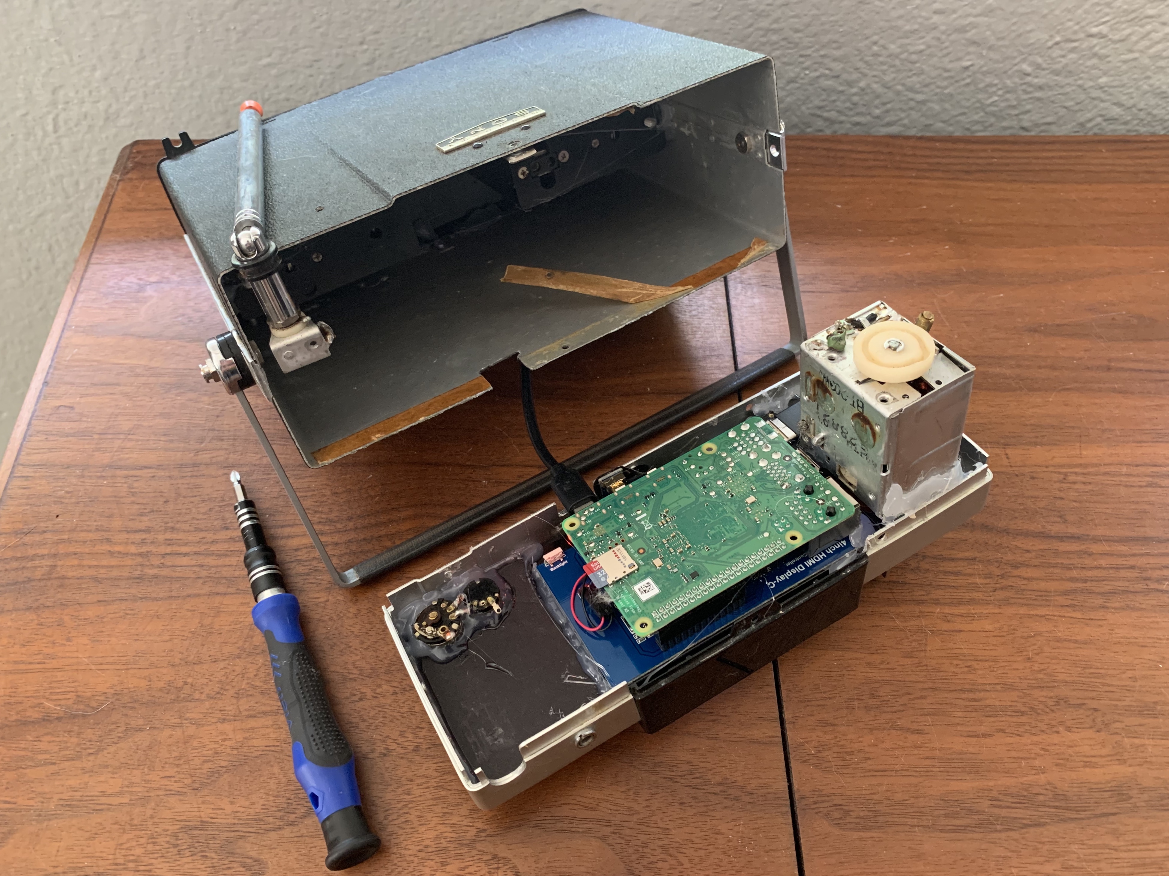
- What I love about the old tube TVs is the rounded shape of the screen. We can either go low tech and cut out a bezel from black card stock to mask our larger 16:9 screen (as pictured), or if you have access to a CNC machine like a Glowforge, you can use the 1/16" black acrylic sheet to do so. The latter will give a much more finished look, but is not possible for everyone (especially every budget - I was lucky to borrow a friends!)
- Here, it'll be good to do a test-fit all of the components before securely gluing the internal components to the foamcore.
- If everything fits, we'll work on the knobs, dials, and buttons first. It'll be important that the knob itself is able to rotate freely, but that the internal component is firmly secured. As you can see, the tuning knob has a much larger piece on the interior, but I still wanted to retain the clicking of the dial, so a lot of glue was used...
- Once we're happy with the knobs, we'll glue our bezel in place - I found that it was easier to place it on the screen (after a test-fit) and apply the adhesive the back-side of the mask (again, either the acrylic or the paper).
- Once the bezel mask is in place, let's go ahead and fix our Raspberry Pi in place.
- Discovered in our earlier test-fit, I did need to drill a hole in the TV's housing to allow for the R-Pi's power cable to come out of the bottom due to how small the internal space of this set is and the limited position of the power supply plug on the R-Pi. Definitely a shortcoming of such a small TV set, but each one is unique.
- Before sealing it up, I placed some electrical tape between any areas of the R-Pi that was touching the TV's components, just to be safe.
- Finally, we reassemble the housing using the screws we laid out on our felt mat (via Adam Savage) or our disposable cups.
Enjoy!
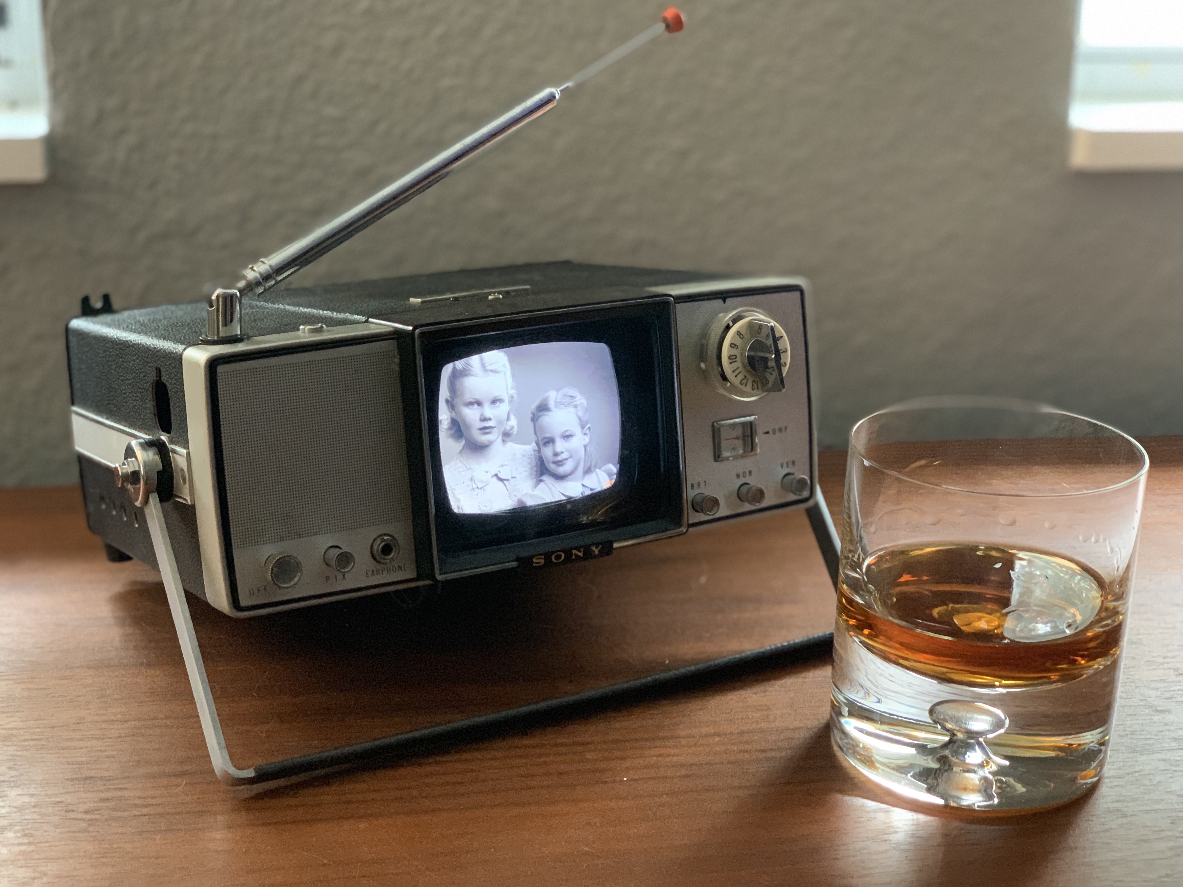
With everything (hopefully) functioning, load up your DakBoard with images and enjoy! I used a trove of vintage family photos in a Google Drive folder, which allows me to update easily, but the option is yours.