Retro No Power No Problem Desk Light.
by Kevr102 in Workshop > Lighting
7614 Views, 63 Favorites, 0 Comments
Retro No Power No Problem Desk Light.


In this Instructable I will show you how I made this very Retro looking Desk Light, I wanted a light to suit a specific brief and I think I have achieved it with this light.
In my shed I have a couple of areas where I put things together etc, I have a couple of double Fluorescent tubes illuminating the areas, and I'm always wishing that I had an additional light, so with that in mind I designed this Retro mainly 3D Printed Dimmable Cantilever Light.
But the best feature of this light is the actual Lamp module, not only is it a hard wired 5v Lamp but the lamp has internal batteries and can used without mains for up to 5 hours! but wait! there's more, with a flick of a lever, the lamp is detachable so it can be used as a Torch! great for those dark nights where I've stayed a bit too long in the Shed:)
So all in all we have a fully adjustable articulating Cantilever Desk Light, which can run off mains or battery power, its dimmable, the module is easily removeable so it can be used as a Torch, and it has a USB charging point, there is an illuminated on/off switch on the base which also illuminates when on battery power in case I forget to turn it off.
The base is made from Oak more for ballast than anything else and will have power socket to the rear, USB to the side
On with the Light Show.
Supplies
Fusion 360 for the Shade, Iris and Cantilever mechanism design.
3D Printer to print the above.
1.75 PLA Black is all I have.
5v LED lamp kit.
Suitable wood for the base.
Chassis mount barrel socket for the base.
Chassis mount barrel socket for the Lamp.
sliding on-off switch.
Push button on off-switch with LED
4 AA Battery holder.
Buck Converter
Cable
CA Glue.
Hot Glue.
15mm Chrome plumbing tubing.
Hand Tools
Hacksaw
Pliers
Soldering Iron & Solder.
CNC Machine for routing the base pocket. 6mm Router bit.
Fusion 360
.png)
.png)
.png)
.png)
.png)
.png)
.png)
.png)
.png)
.png)
.png)
.png)
.png)
.png)
.png)
.png)
.png)
.png)
.png)
.png)
.png)
.png)
.png)
.png)
.png)
.png)
.png)
.png)
.png)
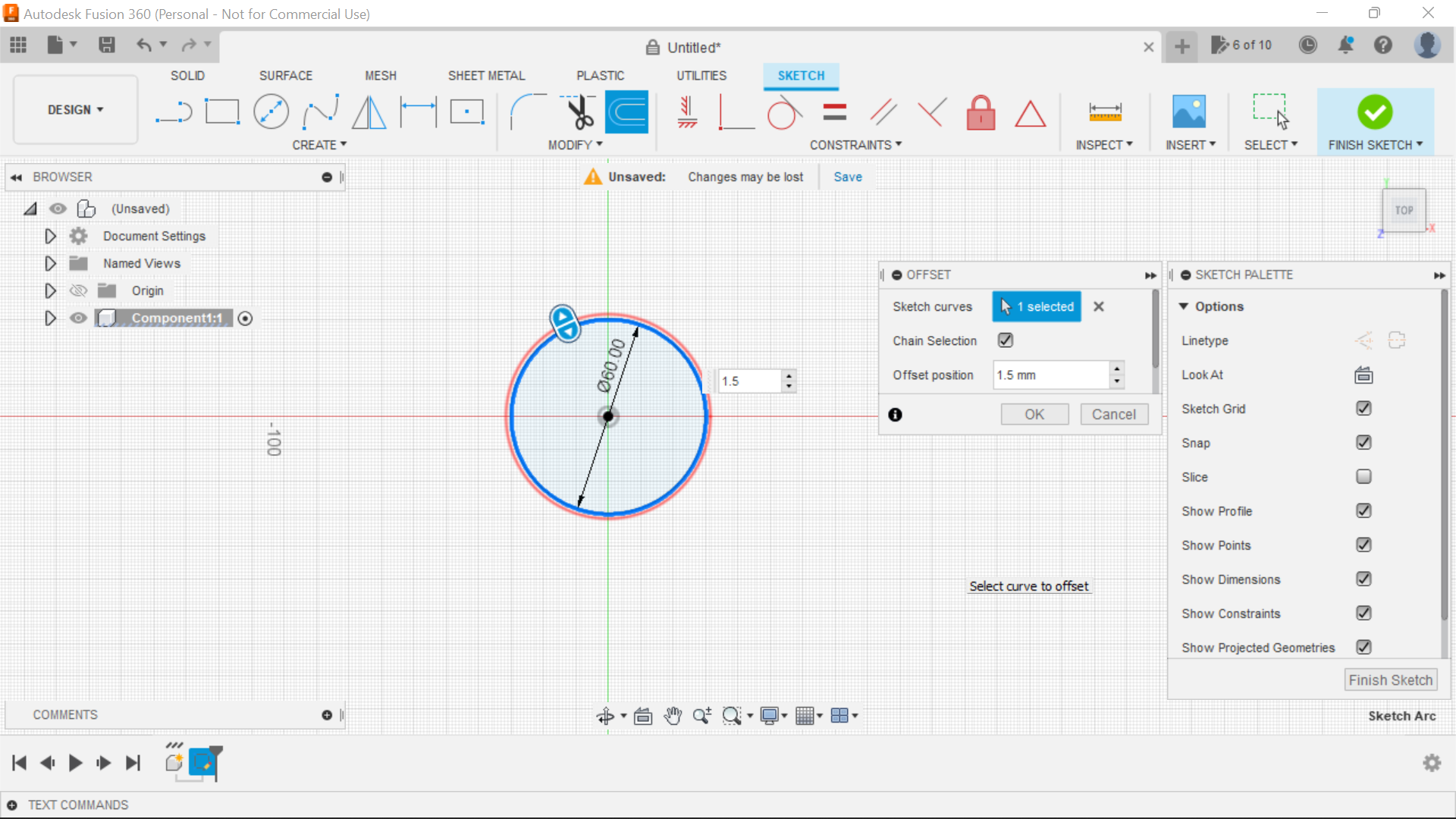
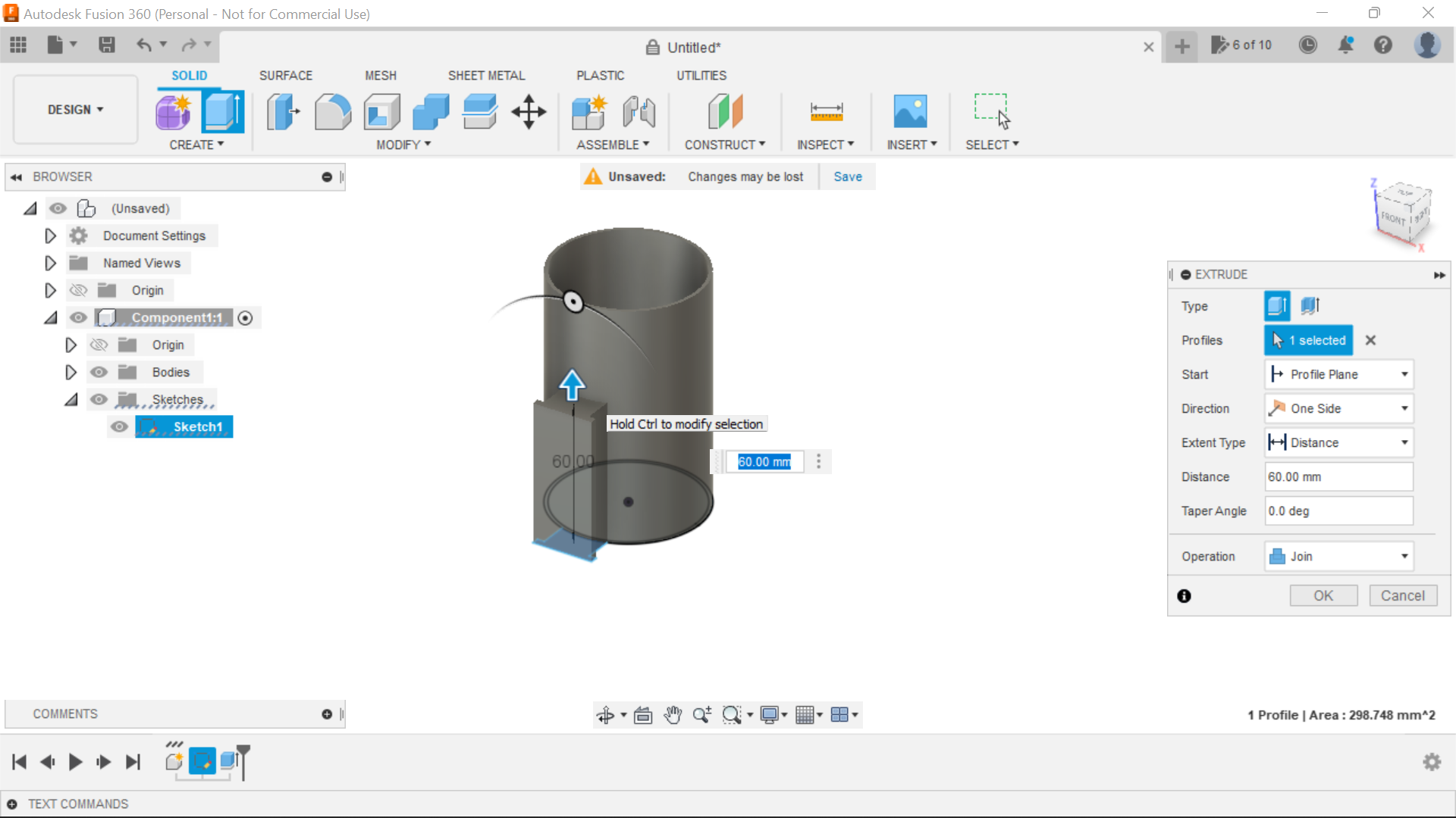
The first thing to do is to create the actual lamp body, Using Fusion 360 I created a new sketch on the Top plane, it can be any diameter you want but I made this one about 60mm, so its a 60 centre circle with a 1.5mm outside offset, also included in the sketch at this time is the slider part which is attached to lamp, please see the screen shots for clarity of this process, but basically its just creating the slider arrangement and then creating a new sketch and projecting the existing slider and off set this to say 0.2mm so the outer slides within the inner.
The lamp body is extruded to 100mm and the slider arrangement 60mm I filleted the slider rail both inner and outer to 1mm.
On the outer part of the slider I created a stop end to stop the lamp sliding off, the lamp module can be used as a torch so has to be removeable, at the other end I created a simple sliding stop, this is a friction fit and slides up the lamp and twists to hold the lamp body in place, this is just a centre circle offset to the outside 2mm and extruded and then a small tab added, when rotated it holds the lamp in situ, rotate again to release the lamp when it's to be used as a torch.
I Created a Lens holder which will house a piece of thin clear Perspex, this is just a push fit over the front of the lamp module.
The same process was applied to the other end of the module end cap, a centre circle was made where I wanted the chassis barrel socket connector and just above that I made provision for the slider switch, once extruded I then made an internal recess for the slider switch to sit in, then secured this with CA Glue.
The slider arrangement so the lamp can be removed and used as a Torch works well, I did the off-set at 0.2mm where 1mm would have been ok, maybe filleting the edges of the slider both Internal and external made things looser, I would sooner have it slide easier anyway and the stop keeps everything in position.
The battery holder is secured to the end cap with Hot Glue as is the LED ring, the ring is adjusted so it sits centrally within the Lamp when in situ, the Buck converter is also secured with hot glue to the side of the battery holder.
To make a handle for the lamp I designed and made 2 stand offs, the bottom of the stand off is the same contour as the Lamp so they can be glued to the body of the lamp, there is a centre circle extrude to each of the pieces so a brass tube can be inserted before gluing the 2nd piece in place, I used a Sharpie pen to colour the brass tube.
To the rear of the lamp module is a 3D printed swivel adapter for lamp up and down movement, this is the next part of the project along with a 3D Printed cantilever arrangement, so we will have a vertical tube coming up from the base through a plastic ferrule, this tube then goes into the cantilever arrangement and then the connecting tube for the lamp slides through the top part of the cantilever arrangement and is completed with an end stop and then to the swivel adapter at the lamp end for full articulation.
Making the Swivel and Cantilever Adapters.
.png)
.png)
.png)
.png)
.png)
.png)
.png)
Just to the rear of the tube that the lamp slides along there is the rotating stop, and beyond this is a 3D Printed swivel, I made this as a rectangular shape rather than round, I just thought it looked stronger and better.
These are sketched as rectangles at 20mm x 20mm and approximately 30 to 40mm in length so it accommodates plenty of the tube for strength, the tube is 15mm so I made the circle 15.2mm and extrude this through the part, the same principle applies to the cantilever bracket as well, the actual swivel is just an inner outer arrangement, a 5mm shallow head bolt is used for securing along with a 5mm nyloc nut, a Polygon recess is made in one side of the lug to accommodate the nut.
The cantilever assembly has a securing screw on the top if the tube is to be fixed in place, the tube within is a snug friction fit so no need for this really, plus it might mark the chrome tube, its fitted but not used.
To the rear of the cantilever assembly I created a slot for the cable exit, the cable will be within the tube from the base and then exit through the rear of the lower assembly and then a loop, then through the cable clips
I sketched and 3D printed an end cap for the cantilever sliding tube, 12mm steel balls can be used within as a counter balance but the base is solid oak with a small recess for the electronics so there should be no movement.
I made a cable restraint, this is just a sliding clip which slides along the tube, and a small ring at the top where the 2 core sleeved cable pushes through keeping things neat and tidy.
The final part to 3D print is the part where the tube fits into the oak base, its a centre circle 50mm extruded to 4mm filleted top edge and then another centre circle from the centre at 15.2mm to accommodate the tube, this was offset to 2mm and extruded 20mm I created 4 holes and chamfered these to accommodate some small black countersunk screws, the tube pushes all the way through this ferrule and is secured within the ferrule with CA Glue or epoxy.
For clarity please refer to the screenshots for not all but some of the processes involved as many use the same principal.
The next part of the project is the electronics:
The Base
I had a piece of oak around 24mm depth, this would be perfect for the base, I cut it to the size I wanted then used the router to radius the top edges of the piece, then using the CNC machine(Following all the correct Health and Safety Guidelines) I cut out a cavity to house the electronics within the base, I kept the cavity to the rear of the base and made this approximately 100mm square with and inboard offset of 6mm and 4mm depth, this will be for the bottom cover, I made the pocket cut depth 19mm allowing for a good size cavity to house the electronics, the bottom cover is pilot drilled and secured with 4 Countersunk screws.
I added dimensions and drilled holes for the barrel power connector to the rear, also the push button on/off switch and dimmer switch in the top and created a slot in the side of the base for the USB.
The vertical tube can now be installed via the 3D printed ferrule which is secured with 4 small black screws.
Power to the Lamp
![IMG_E3546[1].JPG](/proxy/?url=https://content.instructables.com/FCV/QJM6/LB3NRZZW/FCVQJM6LB3NRZZW.jpg&filename=IMG_E3546[1].JPG)
The Mains side of the Lamp will run off a 5v Power supply as the LED Lamp is 5v, the batteries in the lamp are 4 x AA batteries @ 1.5v so this side of things needs a buck converter to drop the 6v current to 5v, be sure to set up the Buck converter to ensure the output is set to 5v before connecting to the LED lamp.
There is barrel chassis socket to the rear of the base and from this the power will come into the base 5v and Gnd and these 2 cables are then fed to a on/off switch, from the switched side of the switch, power is fed to the Dimmer switch power side, I originally fed the USB charging point from here as well but that meant the USB would only be on when the switch was turned on so I wired it straight to the live side of the switch.
The dimmer switch is just a cheap motor speed controller which works well with the LED ring.
5v and Gnd supply in will go to the Dimmer assembly and from there it goes up to the Lamp module barrel socket 5v and Gnd from the switched side.
The remainder of the wiring is in the Lamp module, the Gnd from the battery holder goes to the - In on the buck converter, the 5v from the battery holder goes to the centre pin of the slider switch, the switched wire goes to the + In side of the buck converter and then at the other end of the buck converter the - and + out go to the LED ring.
That concludes the electrical side of the project.
Final Steps


The penultimate task is to cut some neoprene feet for the four corners, I use a a suitable size hole punch to achieve this, the neoprene has an adhesive backing and with a drop of CA glue for good measure, these are secured in place.
So there you have it, a very useful lamp, Fusion 360 designed, mostly 3D printed along with an off-cut of plumbers chrome tubing.
The final task is to step back and admire your handywork:))
I hope you enjoyed this Instructable and thanks for looking.