Retro Digital Clock W/ Raspberry Pi Zero
by AndersSeverinsen in Circuits > Raspberry Pi
15145 Views, 119 Favorites, 0 Comments
Retro Digital Clock W/ Raspberry Pi Zero
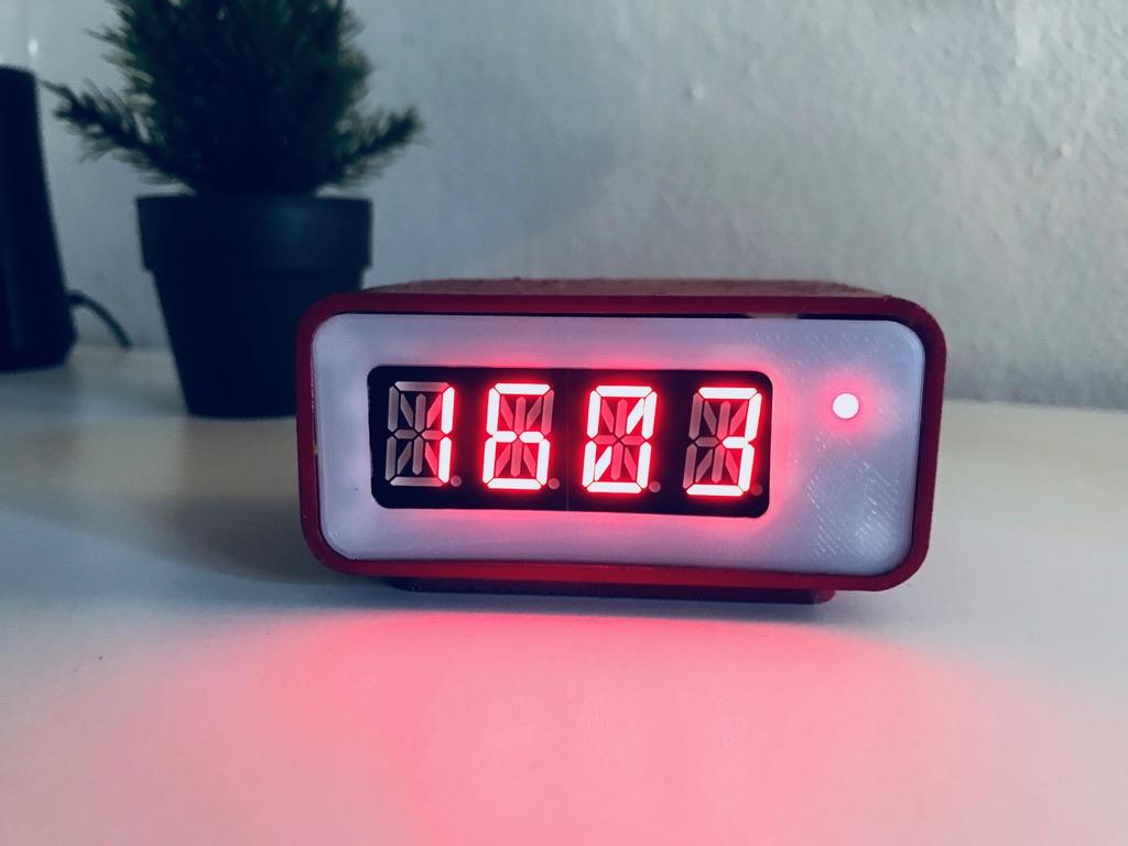
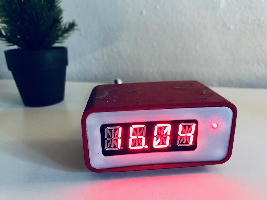
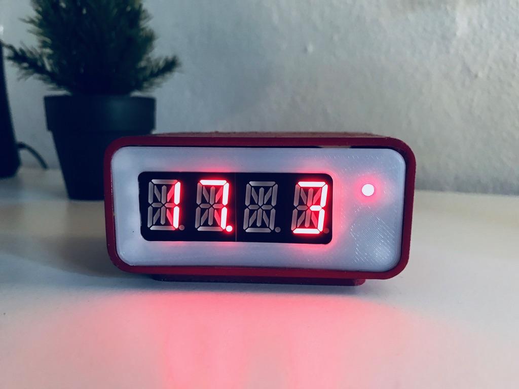
This project combines the amazing retro look, with the almost endless possibilities with Raspberry Pi and IoT.
In this guide I will show exactly how I designed and put together this 3D printed Raspberry Pi Zero retro digital clock.
By default it only displays the current time, but this can of course be customized to have much more functionality, just by adding more lines of code to the simple python program. If you want to, you can make it show the date, or the weather and temperature outside, by using a simple weather api, or maybe you want the display to show the news or current stock market prices.
Feel free to play around with the idea and the design, and customize it to fit your needs.
Supplies
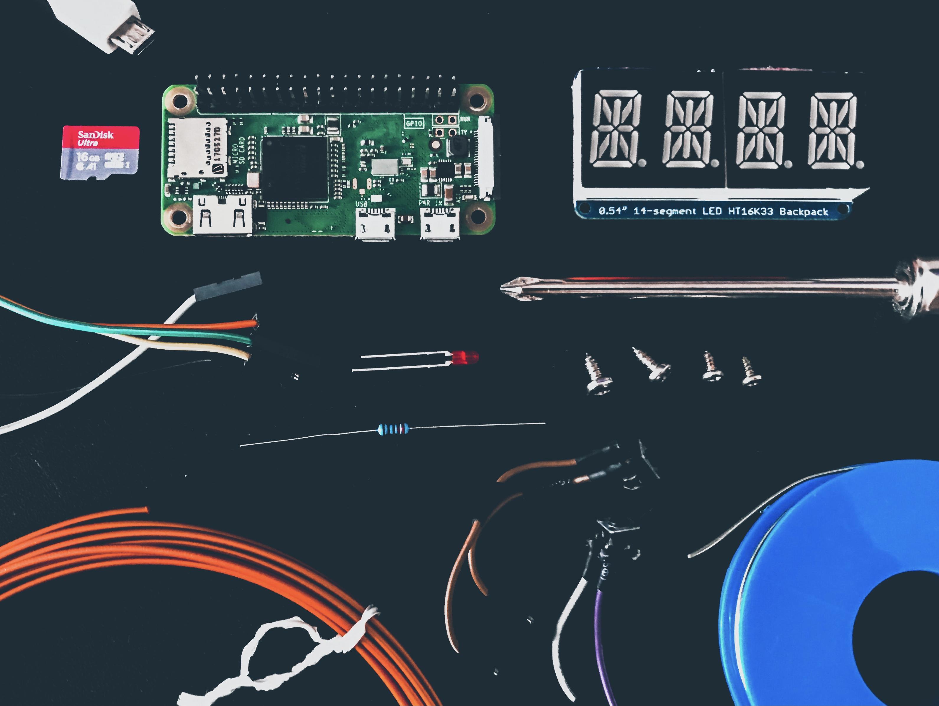
You will need:
- A Micro SD Card (minimum 16GB)
- A Micro USB Charging cable
- A Red 4-Digit Seven-Segment Display or Quad Alphanumeric Display w/I2C Backpack
- Short length female to female jumper cables
- A 3D printer and a spool of any color PLA filament (I used orange (Later primed, then painted silver, then weathered and painted red) and white filament)
- An assortment of small scrap screws (In my case from old scrap electronics)
- A small red LED (d=3mm) with a fitting resistor
- Two small tactile push buttons (6x6mm)
- Heat shrink tubing (Optional)
- A spray primer and silver and red spray paint (Optional: you could just stick to the color of the filament)
Tools:
A soldering iron and solder, needle nose pliers, a hot glue gun and hot glue and a phillips head screwdriver.
Designing and 3D Printing
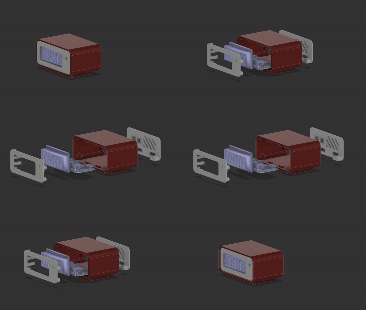
I designed the enclosure myself in Autodesk Fusion 360, to exactly fit the Raspberry Pi and the display snugly. I went for a retro look, and added an indicator LED in the front, for extra detail. On the back i also added space for two small tactile push buttons, which could be used to switch the display og Pi off, or scroll through different functions for the display.
Download the 3D-printable files below.
Parts to be printed: The Base, the Front and the Back.
NOTICE: The Base will have to print with supports enabled.
Painting (Optional):
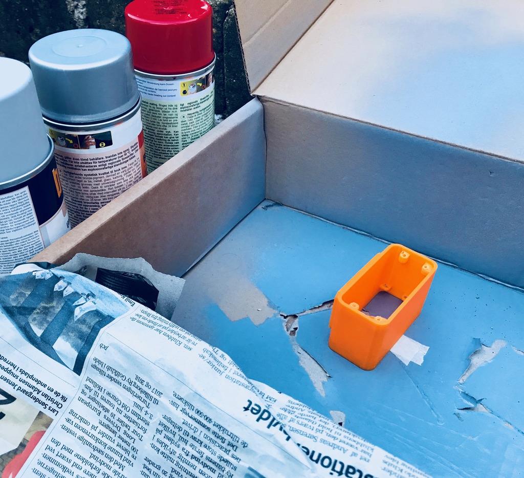
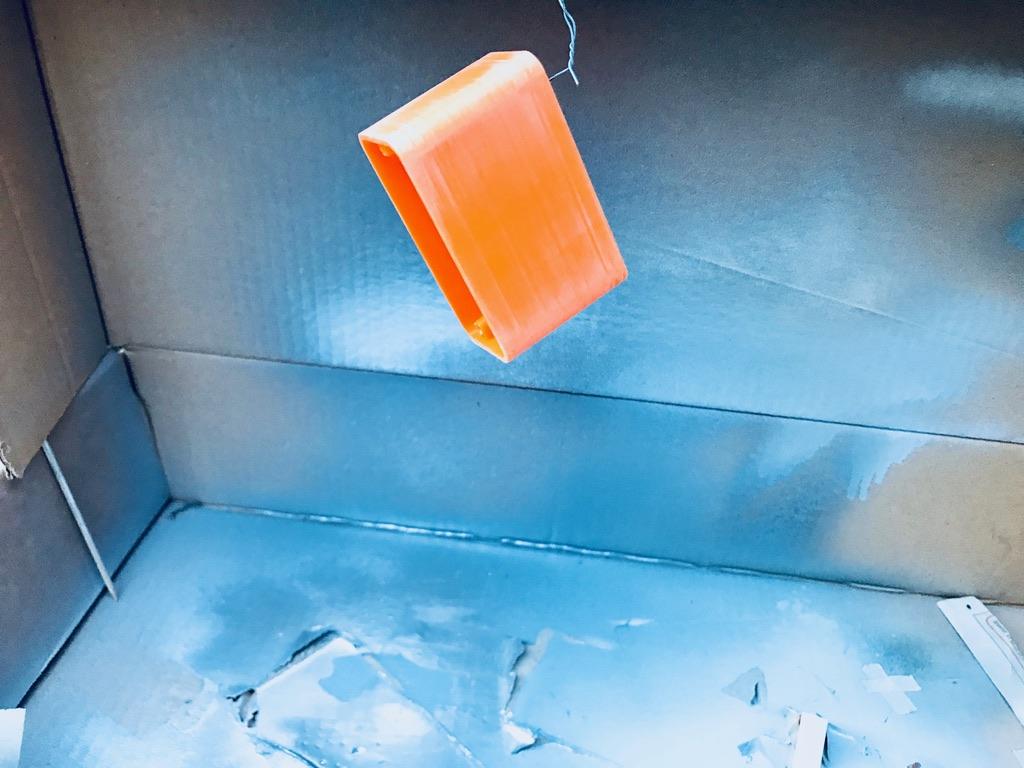

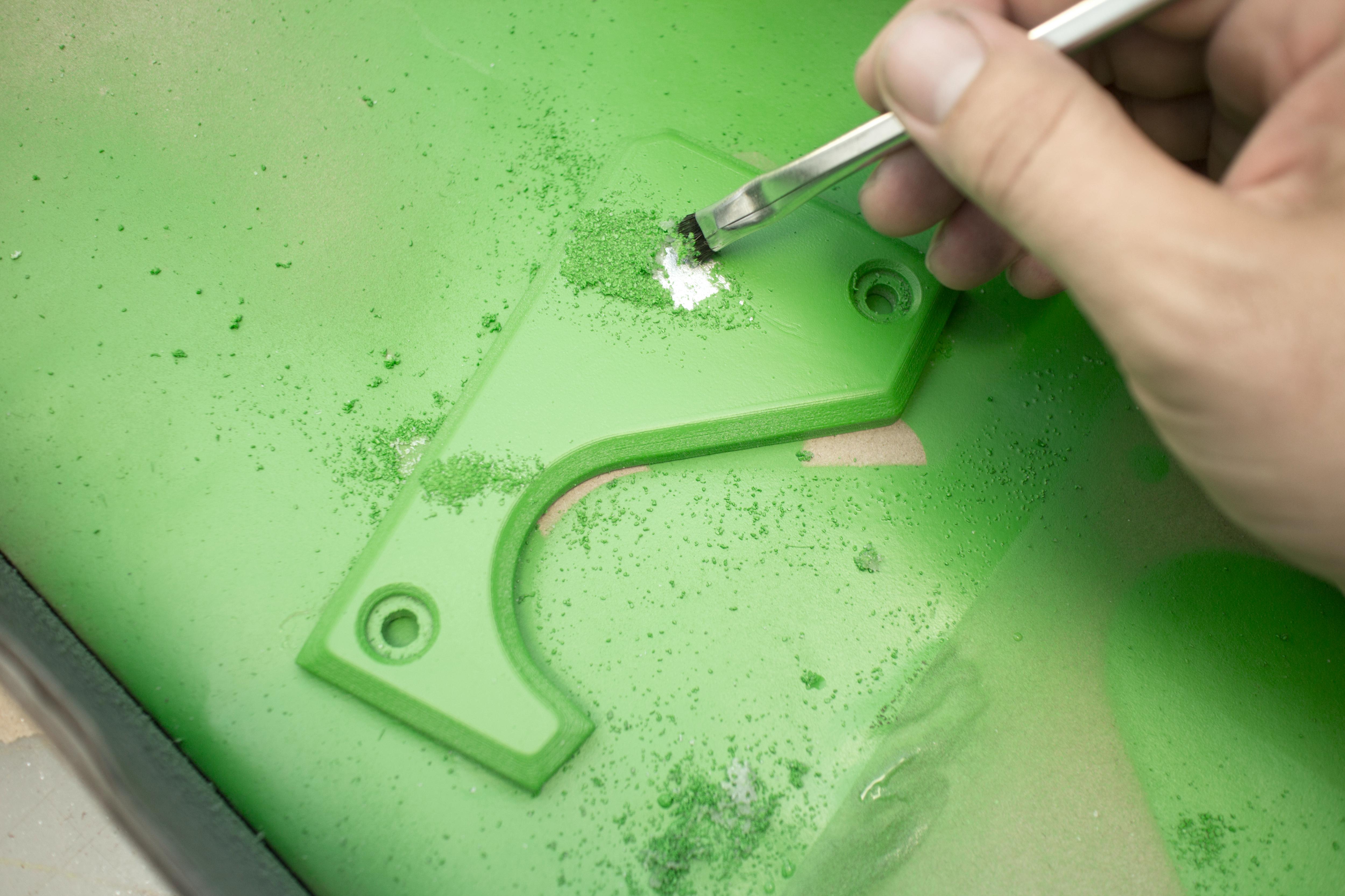
Now this step is completely optional, but I choose to paint mine to make it look retro and worn out. But also to hide the fact that it is 3D-printed, which means priming and sanding the printed parts, to remove the layer lines.
I choose only to paint and weather the base, but not the front and back panels. But it is completely up to you.
Firstly I gave the part a good sanding, to remove some of the layer lines, and to give the paint something to stick to.
Then I gave it a good spray with a primer, followed up with another good sanding.
Then to give it a weathered metallic look, I was inspired by Jonathan Odom, also known as JON-A-TRON on Instructables, and his weathering techniques for making 3D-printed parts look worn and rustic, which he showcased in this Instructable of his.
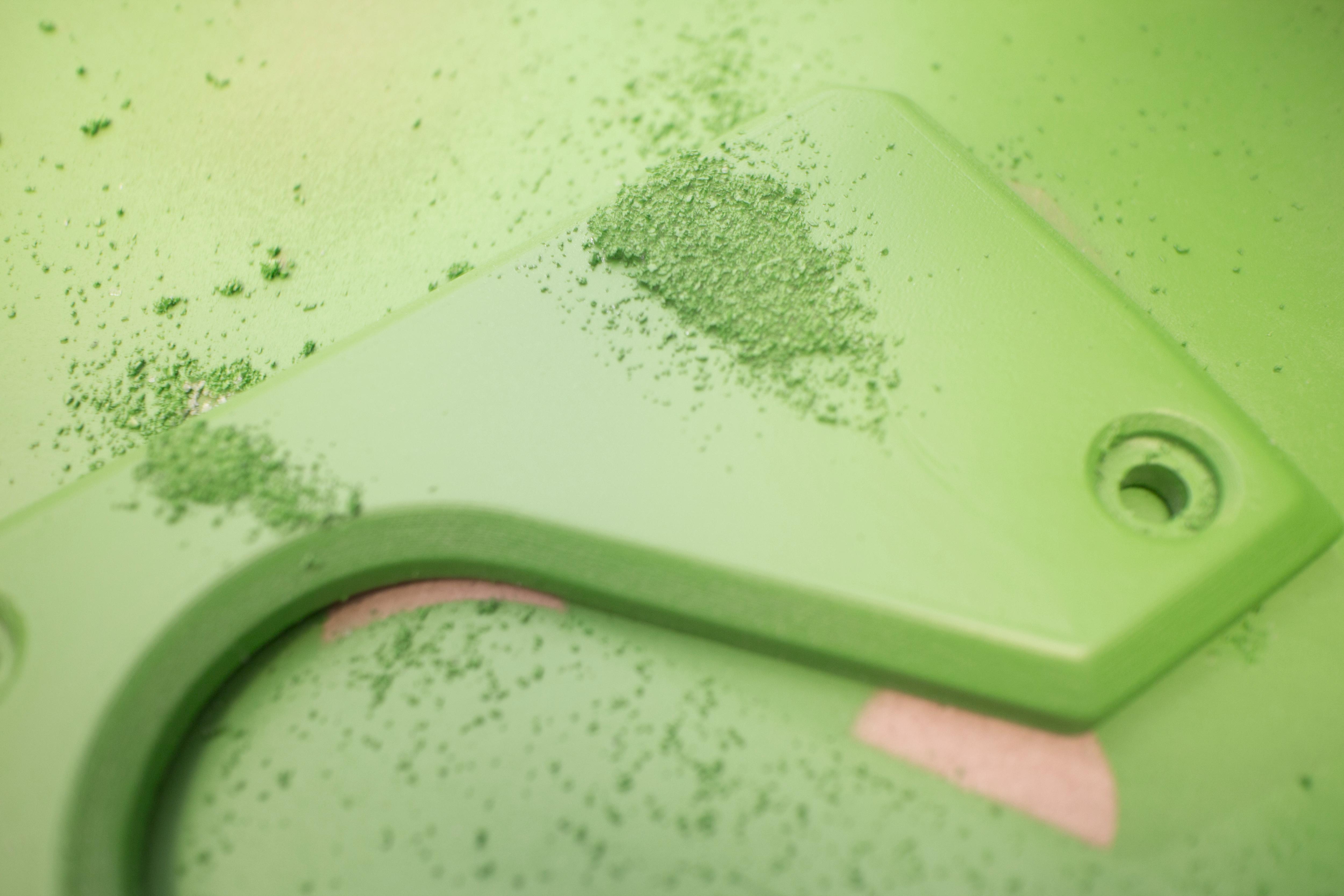
The following steps are from his guide on weathering, as well as the two green images above:
- Paint the parts to be weathered with a base coat. I went with metallic silver.
- Once that coat dries, dab some water on the part then sprinkle salt onto the water. Push the salt into any desired shape.
- Paint the part with a finish coat. Here I used a dark-red colored spray paint.
- Once this coat dries, use a stiff brush (a toothbrush would also work well) to scrub off the salt. This will come off fairly easily and leave a splotchy base coat showing through with a fuzzy edge and some scattered specs around it. It looks very natural when it's done!
The finished weathering turned out like shown in the close-up image.
Setting Up the Micro SD Card
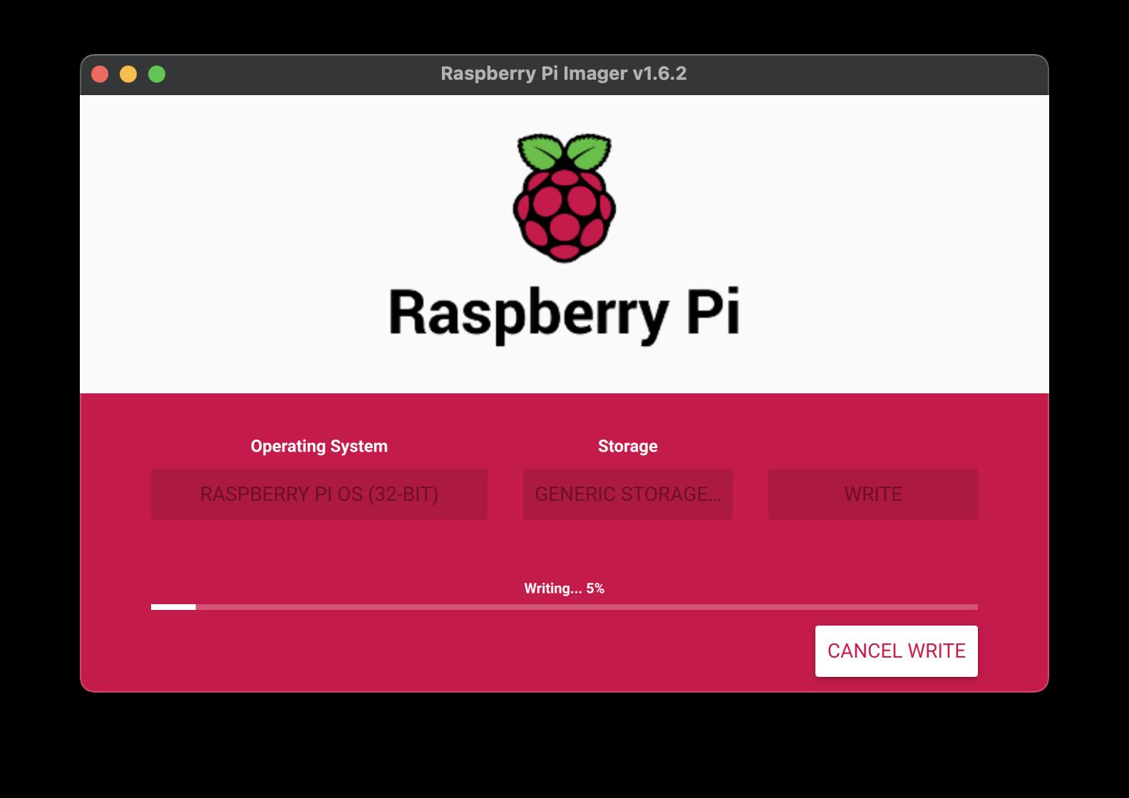
We start by writing Rasberry Pi OS to the Micro SD-card, using the Raspberry Pi Imager, which you can download for free, on the Official Raspberry Pi website.
Plug the SD-card into your computer, and select Rasberry Pi OS as the Operating System, and the SD-card as the storage device.
Hold SHIFT + CTRL + X on your computer, to open the advanced options. Here you will need to enable SSH, and typing in your WIFI credentials.
Last but not least, press Write.
When complete, remove the SD-card, and insert it into the RPI.
Assembly
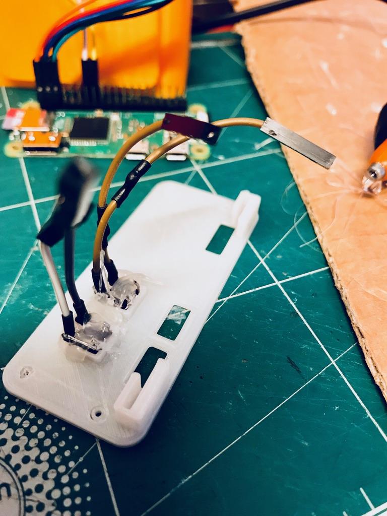
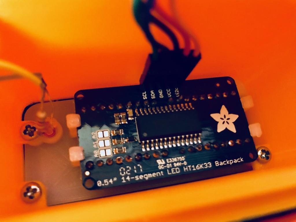
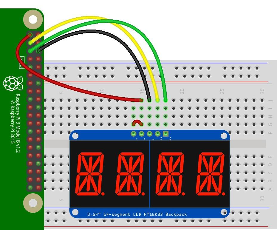
We have now come to assembling the electronics and the enclosure.
Buttons and LED
- First cut the ends off of four female jumper cables, and then solder them to two pins on each of the two buttons, making sure the two different wires are not connected when the button is not pushed. Remember to add heat shrink tubing before soldering.
- Solder the resistor to the positive end of the LED, and solder two other female jumper cables to the end of the resistor and the negative end of the LED.
- Now fit the buttons and the LED into there designated spots, and use hot glue to secure them in place.
- Next fit the display into place in the front, making sure it is turned upright. Additionally also add hot glue if needed, although the fit should already be quite tight.
- Connect five female to female jumper cables to the pins on the back of the display.
Screwing it together
- Start by screwing the Front onto the Base, lining up the screw holes, and screwing it together from the inside.
- Now slide the RPi into the slots on the Back-panel, so that the ports are pointing into the holes, and then screwing it in place, using two small screws.
Connecting the wires
- Then connect the display like shown on the fritzing schematic, as well as connecting the negative jumper from the LED and on of each of the jumpers from the buttons, to one of the available grounds on the Pi.
- Connect the remaining resistor and button female jumpers to any available GPIO pins, on the Pi.
- Now line up the Base with the holes on the Top, and screw them together. Be sure to hold them tightly together, so the screws can screw correctly and tightly on.
- Lastly fit the wires and Pi inside the Base, and screw the Back into place.
Setting Up the RPi
I expect that you are familiar with Raspberry Pi, SSH and Python for the following steps.
Uploading the code
Start by powering the PI, and connecting to your PI wirelessly, using the SSH that we enabled earlier.
1. Enable the I2C and SPI function in raspi-config under Interfacing Options. Exit and reboot.
sudo raspi-config
2. Run these standard commands in the terminal, to update your pi:
sudo apt-get update
sudo apt-get upgrade
sudo reboot
and
sudo apt-get install python3-pip
sudo pip3 install --upgrade setuptools
sudo reboot
3. Run the following commands to install the necessary Adafruit CircuitPython Libraries on RPi:
cd ~
sudo pip3 install --upgrade adafruit-python-shell
wget https://raw.githubusercontent.com/adafruit/Raspberry-Pi-Installer-Scripts/master/raspi-blinka.py
sudo python3 raspi-blinka.py
4. Run the following command to finally install the necessary libraries for the display:
For the full documentation for setting up the display, go to learn.adafruit.com.
sudo pip3 install adafruit-circuitpython-ht16k33
5. Run the following command to open a new python file called "retroclock.py":
nano retroclock.py
6. From the download link below, copy the code for retroclock.py into the newly created file on the RPi:
7. Now exit out of the file, and the code should run when you run this line:
python3 retroclock.py
Downloads
The Result and Final Notes
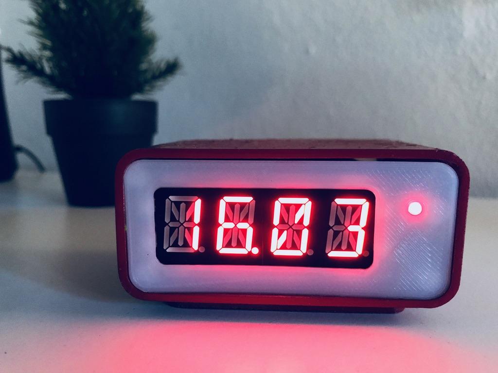
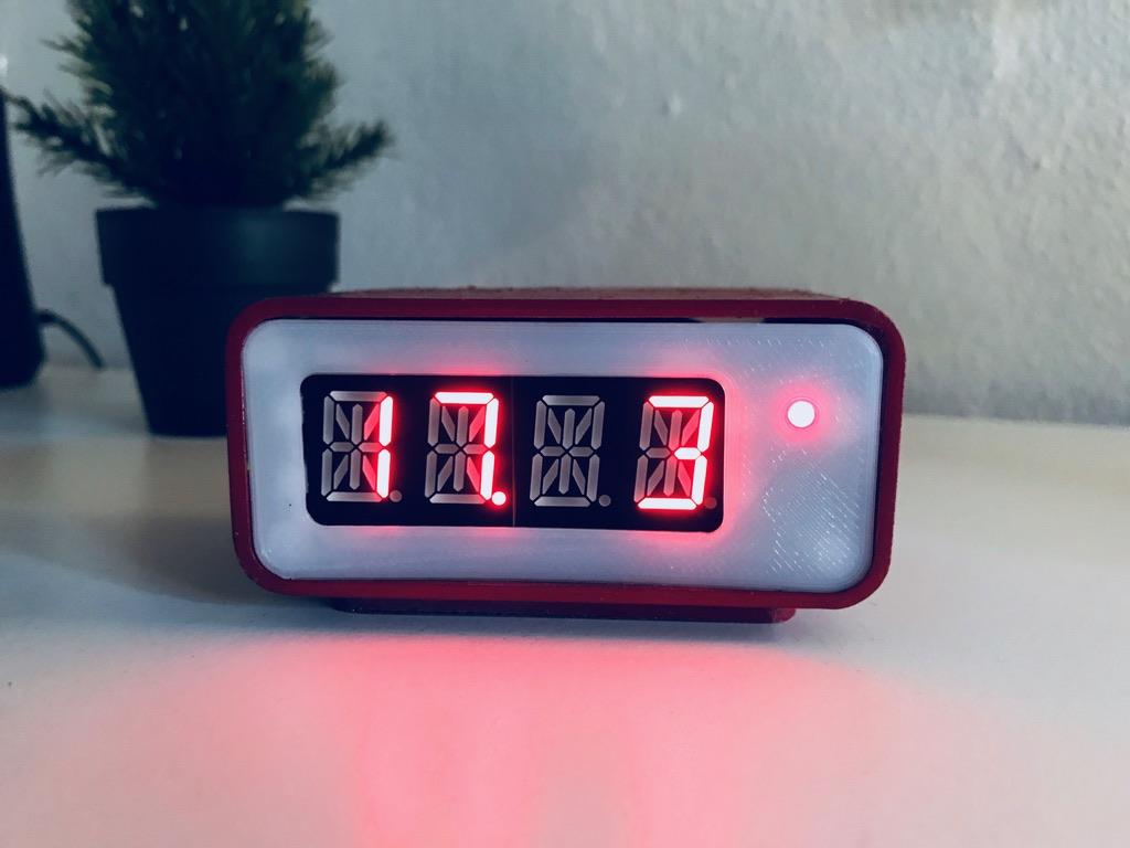
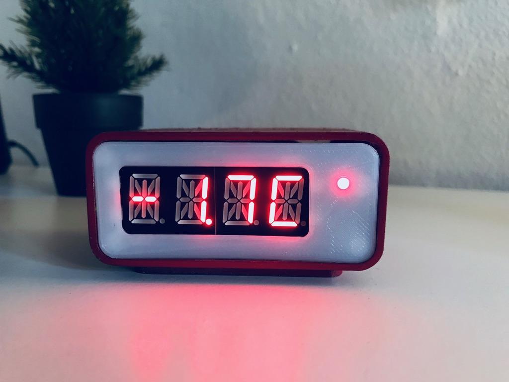
That's it! You have now made your very own retro digital clock, that for now only displays the time, but can be customized to have much more functionality, just by adding more lines of code to the simple python program.
Now feel free to play around with the idea, and customize it to fit your needs.
I hope you liked this project, and if you do, I would very much appreciate it if you wised me best of luck in the RetroTech-contest on Instructables, and feel free to follow me on Instagram and Twitter (@Anders644PI) to keep you updated with what I make.