Repulsor Glove

The Neopixel LED rings look like a repulsor or arc reactor from Ironman movies, right? In one movie scene, Toni Stark only has one glove with him to defend himself against Wintersoldier. I need something like that too! Looks cool and carnival is coming.
Microcontroller - LED ring - mp3player -speaker - flex sensor - power supply
Supplies


Arduino nano / Arduino Mini / Wemos D1 / Seeduino Xiao / Attiny85
DF Player + SD card
Mini speaker (from old device)
Flex sensor (or another kind of switch)
Resistor 5K
LiPo Charge Controller (TP-4056 or similar) or Step-up 5V
LiPo battery 3.7V
Perforated circuit board
Switch
2 Black Gloves
breadboard, wires, hot glue, soldering iron, sewing materials, Velcro tape
Testing on Breadboard


You must save the two (or more?) mp3 sounds on an SD card and insert it into the DF player.
For legal reasons I do not want to place the mp3 files here. But you will certainly find them on the internet.
Software
The software is quite simple:
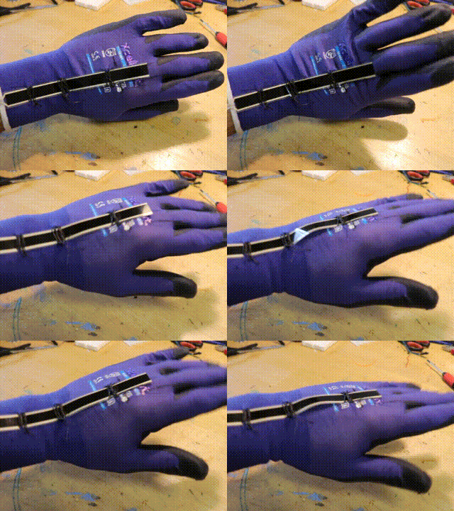
After the setup, the values of the Flex sensor are constantly read out. If the sensor is bent by the wrist, this triggers the lighting and the power-up sound. If the sensor is straightened, the power-down sound is heard and the light is dimmed.
You need a for-loop to address all 12 LEDs on the ring. The colours of the LEDs are composed out of three parameters (RGB). By increasing the blue component by the value 20, the repulsor light appears colder/more intense.
To learn how to use a microcontroller (Arduino nano / Arduino Mini / Wemos D1 / Seeduino Xiao / Attiny85) please check one of the great tutorials on instructables.com.
/* Markus Opitz 2023
 * @ instructables.com
 */

// flex sensor
int flag = 0;
int trigger = 900;

// LED ring
#include <Adafruit_NeoPixel.h>
#define PIN 2   // D2
#define NUMPIXELS 12    // How many NeoPixels are attached to the Arduino?
Adafruit_NeoPixel pixels = Adafruit_NeoPixel(NUMPIXELS, PIN, NEO_GRB + NEO_KHZ800);
int x,y,z;

//DF Player
#include "Arduino.h"
#include "SoftwareSerial.h"
#include "DFRobotDFPlayerMini.h"
SoftwareSerial mySoftwareSerial(11,10); // RX, TX on D11 and D10 of Arduino
DFRobotDFPlayerMini myDFPlayer;


void setup() {


  mySoftwareSerial.begin(9600); //DF Player
  delay(10);

 // DF Player init
  Serial.println();
  Serial.println(F("Initializing DFPlayer ... (may take 3-5 seconds)"));
  if (!myDFPlayer.begin(mySoftwareSerial)) {  //Use SoftwareSerial to communicate with player.
    Serial.println(F("Unable to begin:"));
    Serial.println(F("1.Please recheck the connection!"));
    Serial.println(F("2.Please insert the SD card!"));
    while(true){
      delay(0); // Code to compatible with ESP8266 watch dog.
    }
  }
  Serial.println(F("DFPlayer Mini online."));
  myDFPlayer.volume(25);  //Set volume value from 0 to 30
  //Serial.println(F("df player ready"));


  Serial.begin(9600);
  pinMode(A0,INPUT);  //flex sensor
  pixels.begin();     //LED

}

void loop()  {

  int flex = analogRead(A0); // Reading sensor values
  //Serial.print("Flex1 value = ");
  Serial.println(flex); // Printing Sensor value on Serial monitor


  if ((flex < trigger) && (flag == 0))  {   // start LED light
     myDFPlayer.play(1);
     lightfadeon();
     flag = 1;
  }
  if ((flex < trigger) && (flag == 1)) {     // hold LED light
      lighton();
  }
  if ((flex > trigger+50) && (flag == 1)) {    // fade out light
      myDFPlayer.play(2);
      lightfadeoff();
      flag = 0;
  }
  if ((flex > trigger+50) && (flag == 0))  {   // off
       lightoff();
       flag = 0;
  }
  delay(5);

}

void lightfadeon() {        //repulsor fade on

    //Serial.println(" + + + + + ON + + + + + +");
    for(z=0; z<256; z=z+5)
    {
      for(int p=0; p<12; p++) {
        x = z; y = z;
        if (x>225) x = 225; if (y>225) y = 225;
        pixels.setPixelColor(p, pixels.Color(x,y,z));
        pixels.show();
      }
      //Serial.print(x);Serial.print(", ");Serial.print(y);Serial.print(", ");Serial.println(z);
    }
  }

  void lightfadeoff() {      //repulsor fade off

  //Serial.println(" - - - - OFF - - - - -  ");
  for(z=255; z>=0; z=z-5)
  {
    for(int p=0; p<12; p++) {
      x = z; y = z;
      pixels.setPixelColor(p, pixels.Color(x,y,z));
      pixels.show();
    }
    //Serial.print(x);Serial.print(", ");Serial.print(y);Serial.print(", ");Serial.println(z);
  }
}

void lighton() {      //repulsor on
    for(int p=0; p<12; p++) {
      pixels.setPixelColor(p, pixels.Color(235,235,255));
      pixels.show();
    }
}

void lightoff() {      //repulsor off
    for(int p=0; p<12; p++) {
      pixels.setPixelColor(p, pixels.Color(0,0,0));
      pixels.show();
    }
}
Downloads
Making a Mini Circuit Board


I designed the circuit diagram in an elongated shape so that it fits well on the forearm. Use this circuit diagram as a guide to build a compact circuit with a breadboard and wire connections.
Leave room on the board for a battery!
Sewing Work on the Glove


To be able to put on the gadget without problems, I use two gloves, one for the inside, the outer bigger one as a cover. I can place the cables in between.
Make sure that the gloves are made of some kind of fabric, so you can sew on the cables and LEDs.
First, the flex sensor must be placed correctly on the inner glove. It should be bent through the wrist. I do not sew on the strip itself, but fix it with several sewn loops. The two contacts must stand out on the forearm so that they can be connected to the electronics.
Then we take care of the LED ring. It sits in the hand palm of the outer glove. When you have found the right position, a tiny hole is cut in the glove to lead the cables inside. With several sewn loops the LED ring is now fixed. The LED cables are fixed near the wrist again with sewn loops.
To ensure that the glove can be removed without any problems, the fingertips of the inner and outer glove should be joined together. This can be done with a few stitches or with superglue. (Please do a material test before, to make sure that the glue does not damage the material).
The board is simply attached to the forearm with Velcro and later disappears under the sleeve. Now just connect the sensor and LED, put the sleeve over it - done!
Test It!


Cool, isn't it?
(Replaces a headlamp.)
Now it's up to you to design a solid shell/armor for it. You have the electronics now. Have fun!