Replacing the Screen on a Samsung NP300E5A-A01UB Laptop Computer
by KDS4444 in Circuits > Computers
25743 Views, 5 Favorites, 0 Comments
Replacing the Screen on a Samsung NP300E5A-A01UB Laptop Computer
[Laptop screen used in this Instructable obtained from http://www.LaptopScreen.com]
Whether you have accidentally damaged your current screen or just want to switch from a matte screen to a glossy one, this Instructable will guide you through the steps of replacing the screen on a Samsung NP300E5A-A01UB Laptop Computer. Much of what follows may also be applicable to similar Samsung models (NP300E5A-A02UB, for example) but this is not guaranteed.
Also please note: disassembling your laptop or notebook computer comes with an inherent set of risks: you may accidentally crack a component or lose a screw or forget to reattach a cable somewhere along the line, and then you may have no end of headaches. But if you are sufficiently brave and meticulous, anyone with a screwdriver and some patience can replace their Samsung laptop screen.
The part number for a matte screen for a Samsung NP300E5A-A01UB computer has the code LTN156AT19. The letters "LTN" signify that the screen was designed for a Samsung computer (although this does not limit its use: Toshiba, for example, sometimes uses Samsung screens in its laptops). The next three digits, "156", indicate that the diagonal size of the screen is 15.6". This is a WXGA screen with a resolution of 1366x768 pixels measuring 13.6": across and 7.6" high. Note that other part numbers are apparently not compatible with this particular computer, even if they have the same resolution and dimensions as the original screen.
Replacement screens can cost anywhere from $60 to $140 new. All are manufactured in China. If you order directly from a Chinese distributor, expect the screen to take 3 to 4 weeks to arrive.
Opening the Computer Housing
In order to access the existing screen, you have to open up the computer and disconnect the DVD drive and the hard drive. Note that in this Instructable, the terms "up" and "down" refer to directions relative to the image as seen in the step.
- First, if possible, remove any DVD or CD that is in the DVD drive. Then make sure the computer is unplugged from any power source.
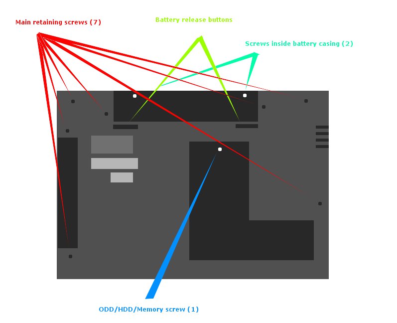
- Next, turn the computer upside down and remove the battery pack. There are two buttons (indicated in the image with arrows in light green) which are spring-loaded and must be simultaneously slid outward-- once both are pushed out, the battery can be released by sliding it up and out. Set the battery aside.
- Next, you must remove the seven basic retaining screws (indicated with red arrows). Like all of the screws on this laptop, these are small Philips -head screws and require a fairly specific size of screwdriver to remove. Once removed, put all of these screws in a small well-marked dish, container, or plastic bag.
- Next, you should remove the two screws inside the battery casing (indicated with teal arrows). Once these are out, put them in another dish/ bag.
- Next, you should remove the single ODD (Optical Disk Drive)/ HDD (Hard Disk Drive)/ Memory cover screw (shown with a blue arrow). Put this in yet another dish/ bag. You can now remove the ODD/HDD/Memory cover (it slides downward and then lifts out, see image).
- First, if possible, remove any DVD or CD that is in the DVD drive. Then make sure the computer is unplugged from any power source.
- Next, turn the computer upside down and remove the battery pack. There are two buttons (indicated in the image with arrows in light green) which are spring-loaded and must be simultaneously slid outward-- once both are pushed out, the battery can be released by sliding it up and out. Set the battery aside.
- Next, you must remove the seven basic retaining screws (indicated with red arrows). Like all of the screws on this laptop, these are small Philips -head screws and require a fairly specific size of screwdriver to remove. Once removed, put all of these screws in a small well-marked dish, container, or plastic bag.
- Next, you should remove the two screws inside the battery casing (indicated with teal arrows). Once these are out, put them in another dish/ bag.
- Next, you should remove the single ODD (Optical Disk Drive)/ HDD (Hard Disk Drive)/ Memory cover screw (shown with a blue arrow). Put this in yet another dish/ bag. You can now remove the ODD/HDD/Memory cover (it slides downward and then lifts out, see image).
Removing CD/DVD Drive and Hard Drive
The next step is to remove the two main drives of the computer.
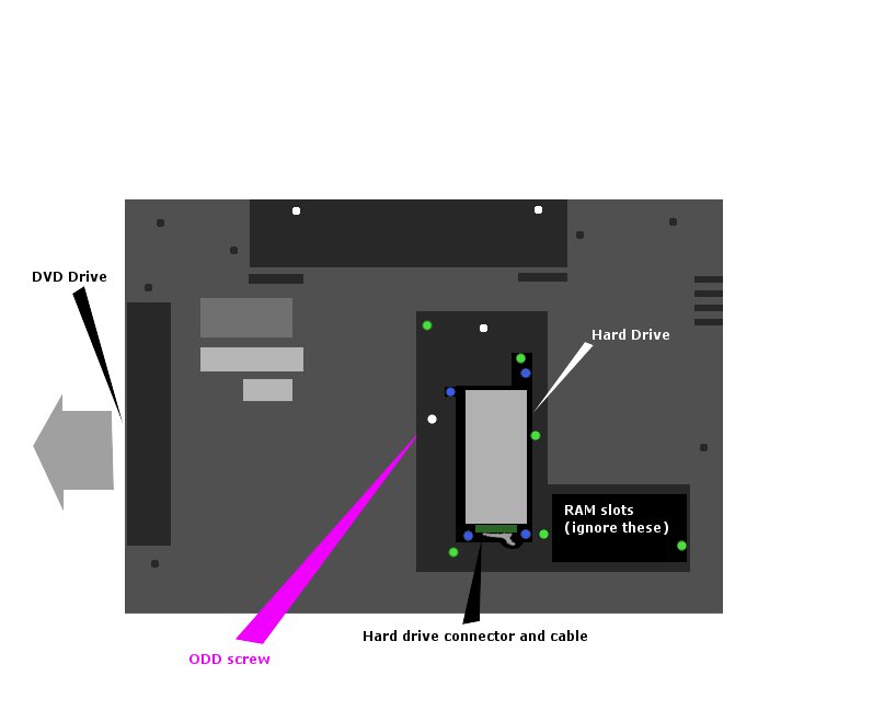
- Inside the ODD/HDD/Memory compartment there is a screw marked ODD (shown with a purple arrow). Remove the ODD screw. Set aside.
- Next, remove the six internal retention screws (screws shown here in green). Set these aside.
- Then, remove the four hard drive retention screws (shown in blue) and set these aside. The hard drive (shown in light gray) is now lose inside its recessed opening. Lift it out of this compartment and detach the hard drive cable by gently pushing the connector (which is shown here in dark green) off the end of the hard drive. Set the hard drive aside.
-The DVD drive is now also loose. Slide the DVD drive out of its slot by gently pulling on it from the left. It may require some wiggling, but it should come loose fairly easily once the ODD screw has been removed (see the beginning of this step). Once it is out, set the DVD drive aside.
Removing Bottom of Case
The next step is to remove the entire bottom of the computer case. This will only be possible once all of the aforementioned screws have been removed. Also, make sure you have not left an SD card in the SD card slot as this will hamper the removal process.
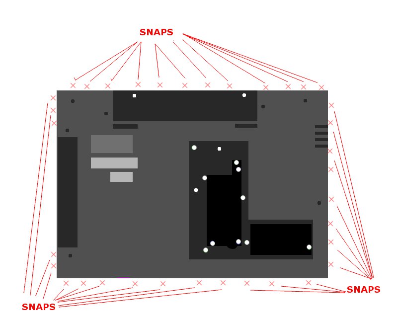
The bottom of the case is held in place by a series of 25 snaps that encircle the computer's edge. You will need to work a thumbnail under the edge of the case at any point and pry up a snap. Note that these snaps are quite strong and are deliberately difficult to dislodge-- you must be persistent but gentle. Eventually, once the first snap comes lose, the others will follow suit. Go all around the bottom of the case and undo all of the snaps. The bottom of the case will now lift up. Thread the hard drive cable and connector out through the opening that allows them to attach to the hard drive, and set the bottom of the case aside. This step will likely take 10-15 minutes to complete, possibly longer if the snaps prove difficult. Do not crack the bottom of the case.
The bottom of the case is held in place by a series of 25 snaps that encircle the computer's edge. You will need to work a thumbnail under the edge of the case at any point and pry up a snap. Note that these snaps are quite strong and are deliberately difficult to dislodge-- you must be persistent but gentle. Eventually, once the first snap comes lose, the others will follow suit. Go all around the bottom of the case and undo all of the snaps. The bottom of the case will now lift up. Thread the hard drive cable and connector out through the opening that allows them to attach to the hard drive, and set the bottom of the case aside. This step will likely take 10-15 minutes to complete, possibly longer if the snaps prove difficult. Do not crack the bottom of the case.
Disconnect Lid Hinges
Congratulations, you are now looking at the inner workings of the laptop. The next step is to disconnect the lid and screen from the rest of the computer by disconnecting the hinges and cable that attach them.
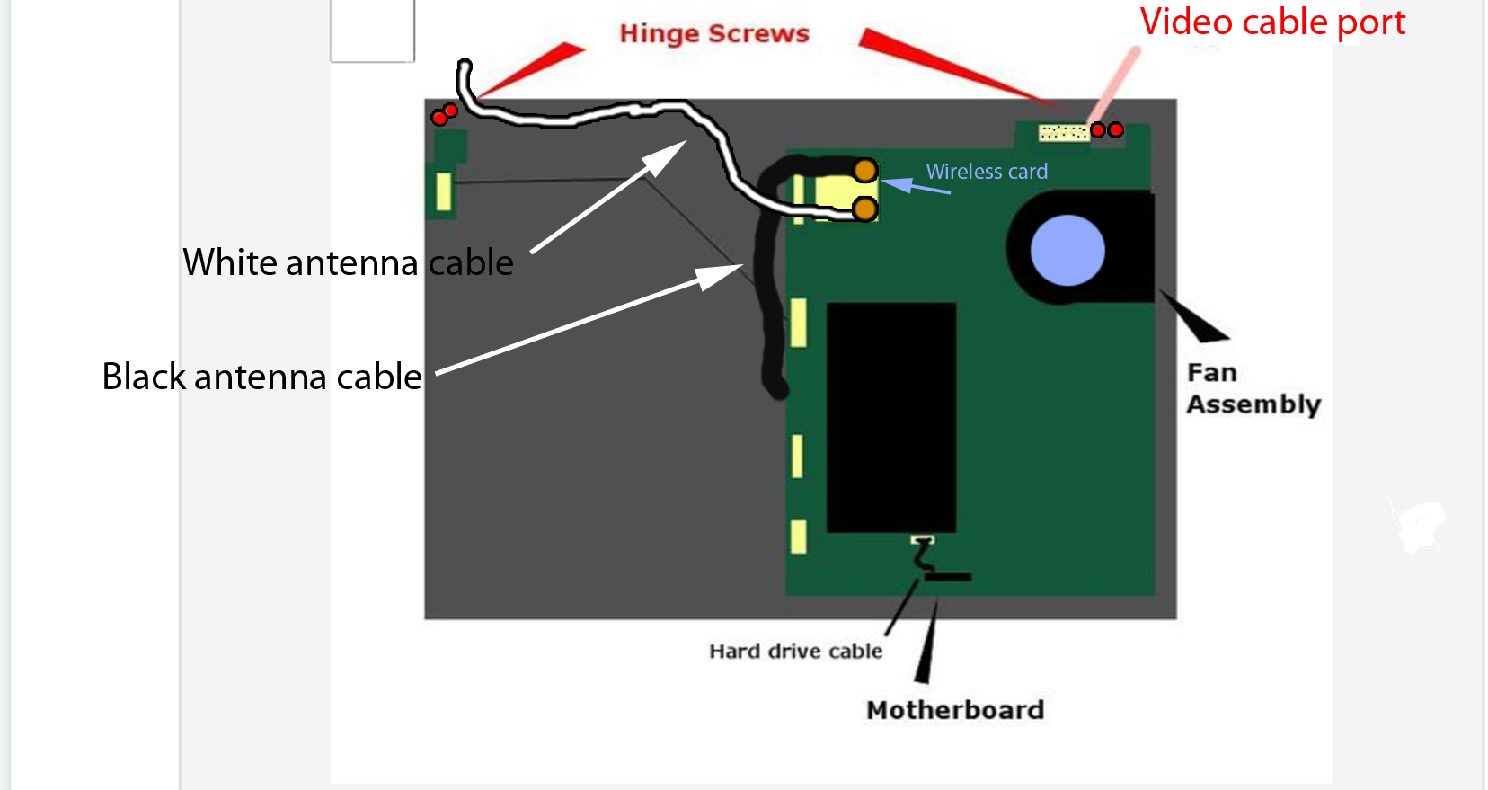
- First, disconnect the video cable from the motherboard by gently sliding it out of its port.
- Next, along the top edge towards the extreme left and right sides of the case are a total of four hinge screws (marked in red).. Unscrew and remove all four of these hinge screws. Set them aside.
- Lastly, you must disconnect the white antenna cable. The whole antenna consists of a black cable and a white cable that both attach with small round gold tabs to the wireless card on the motherboard (wireless card shown here as the large white square). Both the white and black cables attach to this card, but only the white cable needs to be disconnected to fully remove the lid assembly. The small round gold tab should be pried up using your fingertips-- it is held on with tension only (no screws or snaps),
The lid is now disconnected from the rest of the computer Set the computer part aside. We will now focus on the lid.
Opening Up the Lid and Removing the Screen
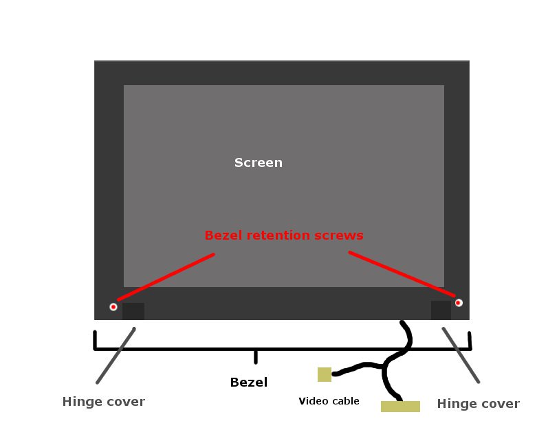
The next step is to open up the lid to gain access to the screen proper. The lid is composed of three layers: the bezel, the screen, and the cover. The bezel is a thin square plastic "frame" that goes around the screen and helps secure it to the cover.— it is flat except for two hinge flaps along its bottom edge. The screen is the meat of the sandwich. We need to remove the bezel to gain access to the screen.
- The bezel is held in place by only two screws, one at the lower right and the other at the lower left of the display (see first image). Remove both of these bezel screws. Set them aside.
- Next, the bezel must be unsnapped from the rest of the lid. Like the bottom of the computer case, it is held in place by a series of very strong snaps. Using a fingernail, again undo all of the bezel snaps, going all around the outside of the display. Once all of the snaps have been released and the screws removed, the bezel can be lifted out. Remove the bezel and set aside.
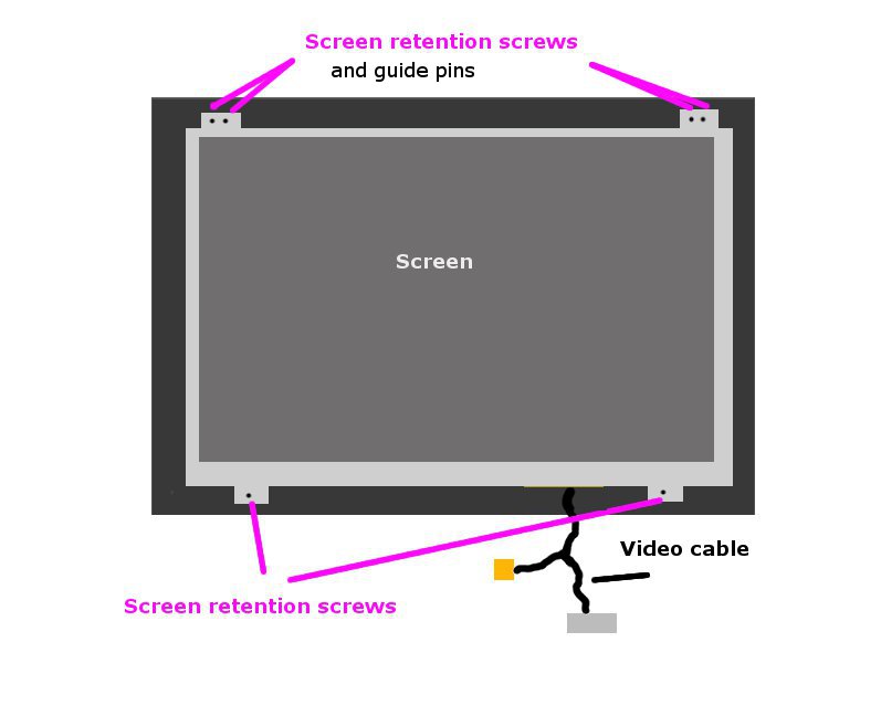
- You are now looking at the naked interior of the lid. The next step is to remove the old screen from the cover. The screen is held in place by four screws and two video cable connectors on one video cable (see second image). Remove all four of the screen retention screws.
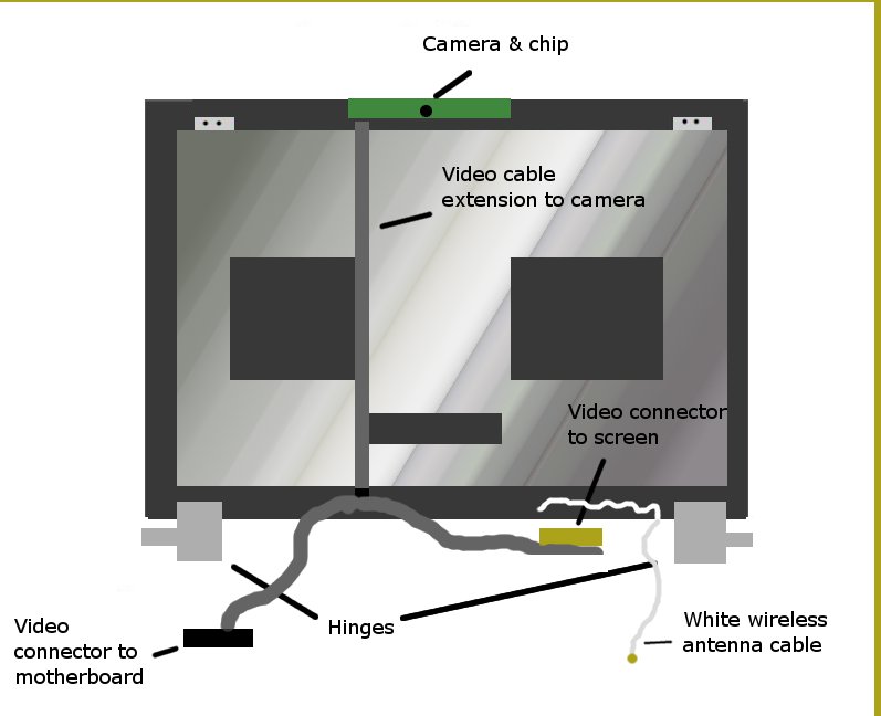
- Next, disconnect the video cable from the screen by sliding it down and out of position. The screen may now be lifted free of the lid. This will reveal the metallic shield of the inside cover (see third image). The video cable (called a CBF harness and LCD assembly cable) runs down along the left side of this shield from the camera at the top of the lid to the Y-connection that goes to the screen (at one end) and the motherboard (at the other).
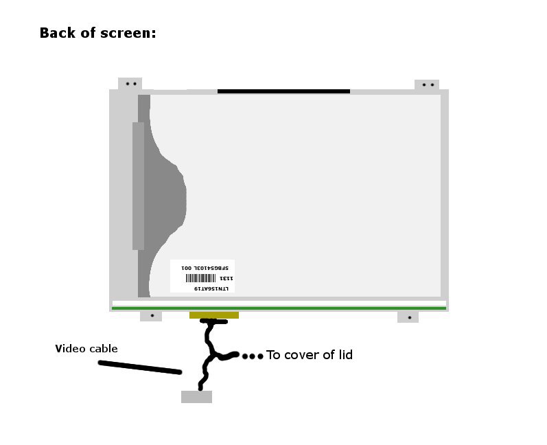
If you flip the screen over (see fourth image) you can see where the video cable connects to the chip inside the lid, and you can see the part number for the screen itself.
- The bezel is held in place by only two screws, one at the lower right and the other at the lower left of the display (see first image). Remove both of these bezel screws. Set them aside.
- Next, the bezel must be unsnapped from the rest of the lid. Like the bottom of the computer case, it is held in place by a series of very strong snaps. Using a fingernail, again undo all of the bezel snaps, going all around the outside of the display. Once all of the snaps have been released and the screws removed, the bezel can be lifted out. Remove the bezel and set aside.
- You are now looking at the naked interior of the lid. The next step is to remove the old screen from the cover. The screen is held in place by four screws and two video cable connectors on one video cable (see second image). Remove all four of the screen retention screws.
- Next, disconnect the video cable from the screen by sliding it down and out of position. The screen may now be lifted free of the lid. This will reveal the metallic shield of the inside cover (see third image). The video cable (called a CBF harness and LCD assembly cable) runs down along the left side of this shield from the camera at the top of the lid to the Y-connection that goes to the screen (at one end) and the motherboard (at the other).
If you flip the screen over (see fourth image) you can see where the video cable connects to the chip inside the lid, and you can see the part number for the screen itself.
Attach New Screen & Re-Assemble
Attach your new screen and re-assemble the computer:
- Attach the video cable (correctly) to the back side of the new screen.
- Flip the new screen over and re-secure the screen to the lid using the four retention screws removed in the last step. Line the screen up so that it fits into the guide pins along the top edge before inserting the screws. If you unthreaded the video cable from its channel along the bottom of the lid, you must re-thread it now. The video cable leads out through one of the hinge flaps and the white antenna cable leads out through the other.
-Attach the bezel to the front of the lid assembly: place the bezel over the new screen and push all of the bezel snaps back together; then re-attach the two bezel screws.
- Secure the lid assembly back onto the rest of the computer using the four hinge screws removed two steps ago.
- Re-attach the main video cable connector to its port on the motherboard.
- Re-attach the white antenna cable to the wireless card. Close the lid.
- Replace the bottom of the computer case: thread the hard drive cable back through its original opening and push the bottom of the computer case back into place by pressing on all of the edge snaps. Any snaps you happen to miss will be easily visible-- make sure all of these snaps are correctly back in place before proceeding.
- Replace the hard drive into its recessed opening: re-attach the hard drive cable onto the hard drive and re-secure the hard drive using the correct screws from Step 2.
- Re-insert the DVD drive by pushing it gently back into position. Use the ODD screw from Step 2 to secure it into place. If it is not correctly inserted, this screw will not thread: keep pushing on the front of the drive until you feel it slide into its port on the motherboard, then attempt to re-attach the screw.
- Close the ODD/HDD/ Memory cover and re-secure it using the appropriate screw.
- Replace all seven of the bottom case retention screws.
- Replace the battery by sliding it back into its original position. It will "click" when correctly inserted. There is no need to hold the spring-loaded buttons in the open position to accomplish this.
- Turn the computer over. You may now re-attach the main power supply cable. Open up the lid and press the power button. The computer will now begin to boot up. If you have attached the screen correctly, within a few seconds you will see the Samsung logo appear on the new screen. If any part of the connection between the motherboard and the new screen is not secure, you will see nothing: turn the computer back off by holding down the power button until the computer powers down, then disconnect the power cord and battery before disassembling the computer and checking all of the cable connections.
With some luck, you have now successfully replaced the screen on a Samsung NP300E5A-A01UB laptop computer. Congratulations.