Repair a Gramophone Soundbox/Reproducer With 3D Printed Die
by JGJMatt in Workshop > Repair
5176 Views, 24 Favorites, 0 Comments
Repair a Gramophone Soundbox/Reproducer With 3D Printed Die


Please consider subscribing to my YouTube channel for more projects
Hello fellow makers!
A few weeks ago after a lot of searching I was finally able to find a nice old Columbia gramophone on one of our local auction sites.
Unfortunately the shipping company was a "little" careless and I received a gramophone with a lot of repairs needed, Except for the cosmetic repairs the biggest problem was that the tone-arm came out of its holder and smashed the needle into the box causing the aluminium diaphragm to tear apart.
Now if you are lucky you might still be able to find replacements in your country but after some Googling I only had one option....DIY!
(Admittedly I didn't mind as I always love a DIY challenge)
Let's get stared with our brand spanking new diaphragm...
What You Will Need:
You will need the following:
- The broken soundbox/reproducer
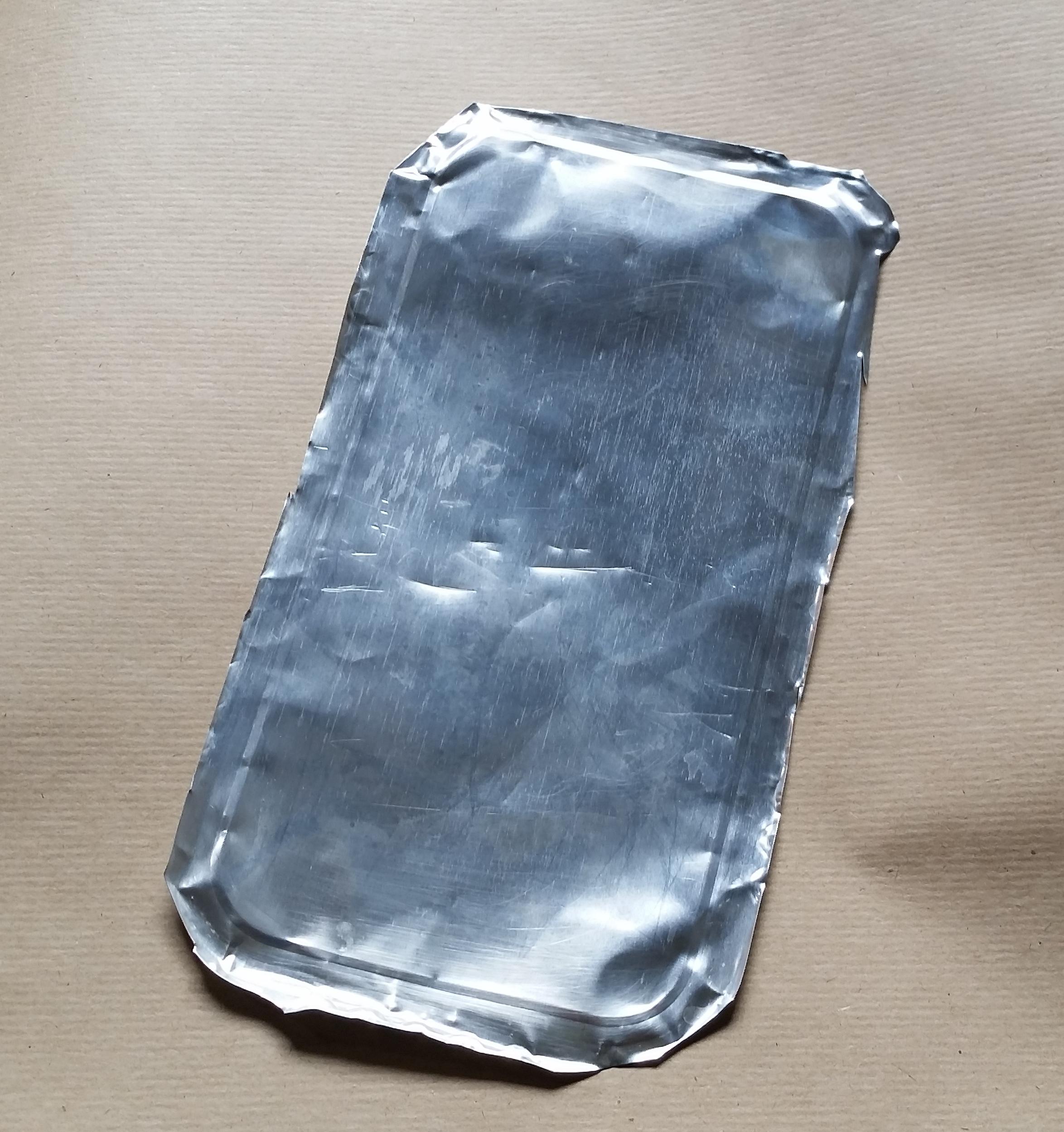
- Some thin (0.1-0.2mm) aluminium
I went through a lot of rummaging to find the perfect aluminium and the one that I found works best is the bottom of "heat and eat" meal containers (These are the matt/dull looking ones that are suitable for microwave use) they are the exact thickness of the original diagram and can take a lot of deforming without cracking which is very important.
- Access to a 3D printer
- About 2 meters of PLA filament
- Beeswax or candle wax
I used pure beeswax.
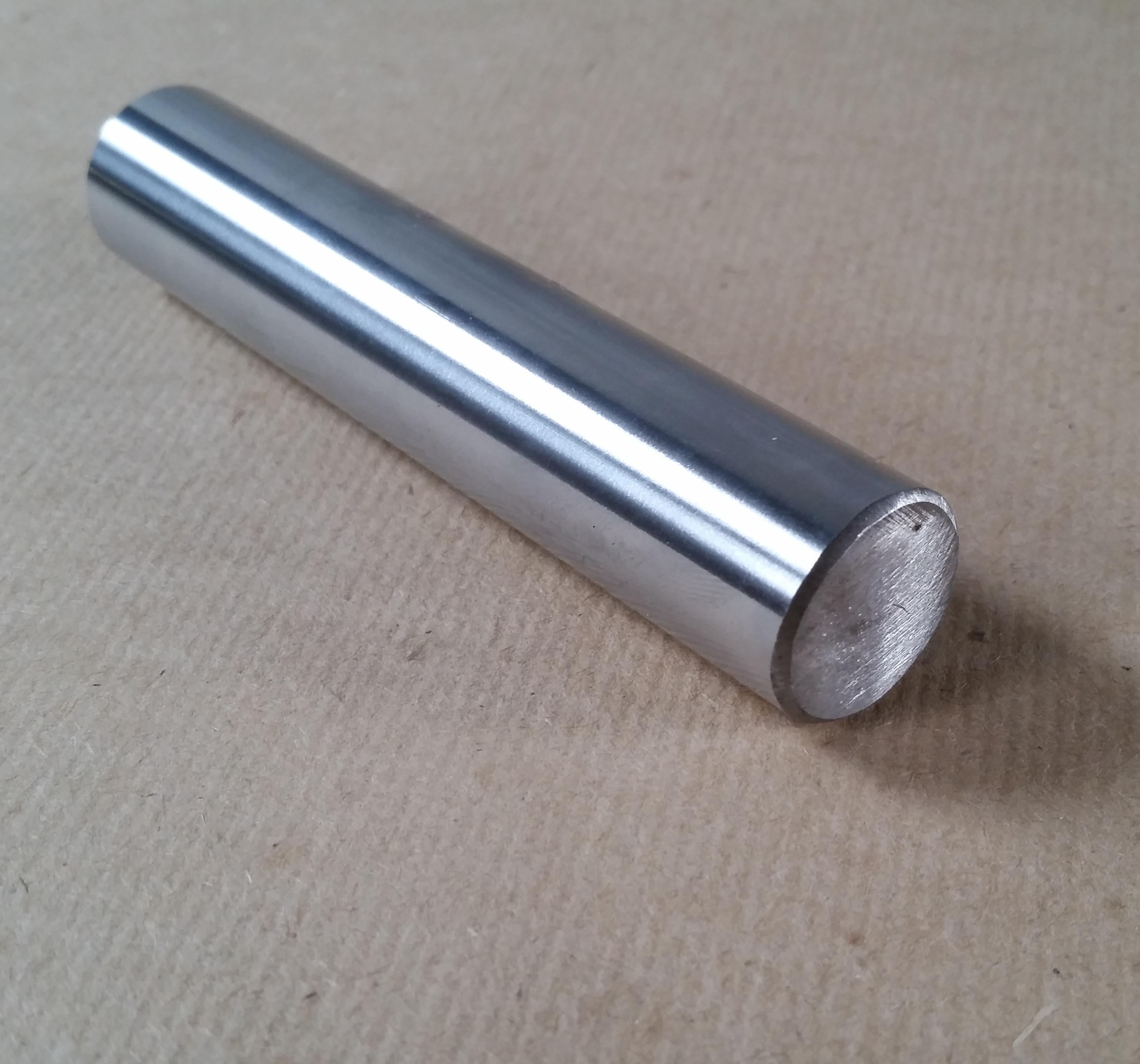
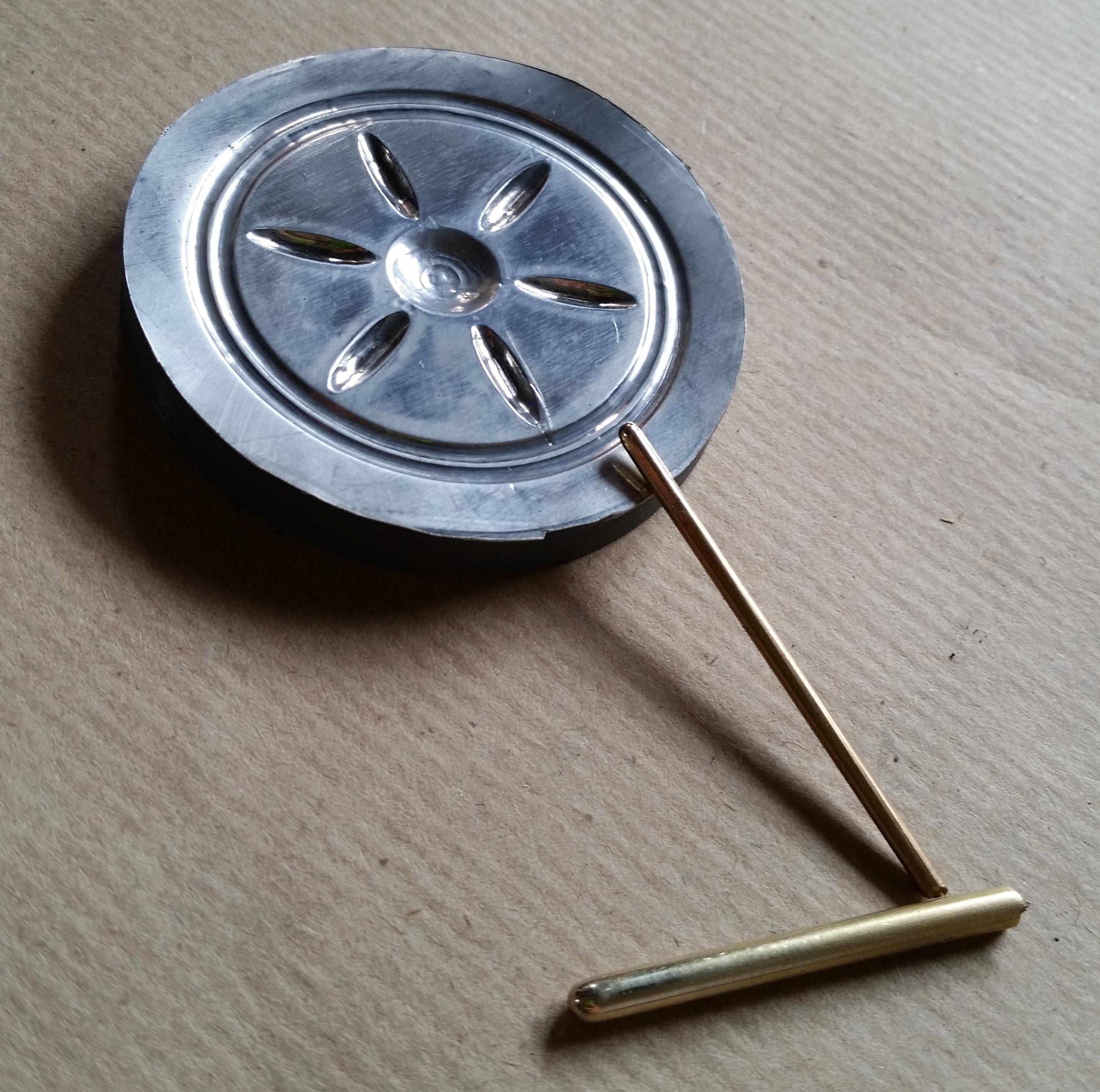
- A thick smooth metal staff
I used an off-cut piece of 20mm stainless steel rod.
- Sanding paper
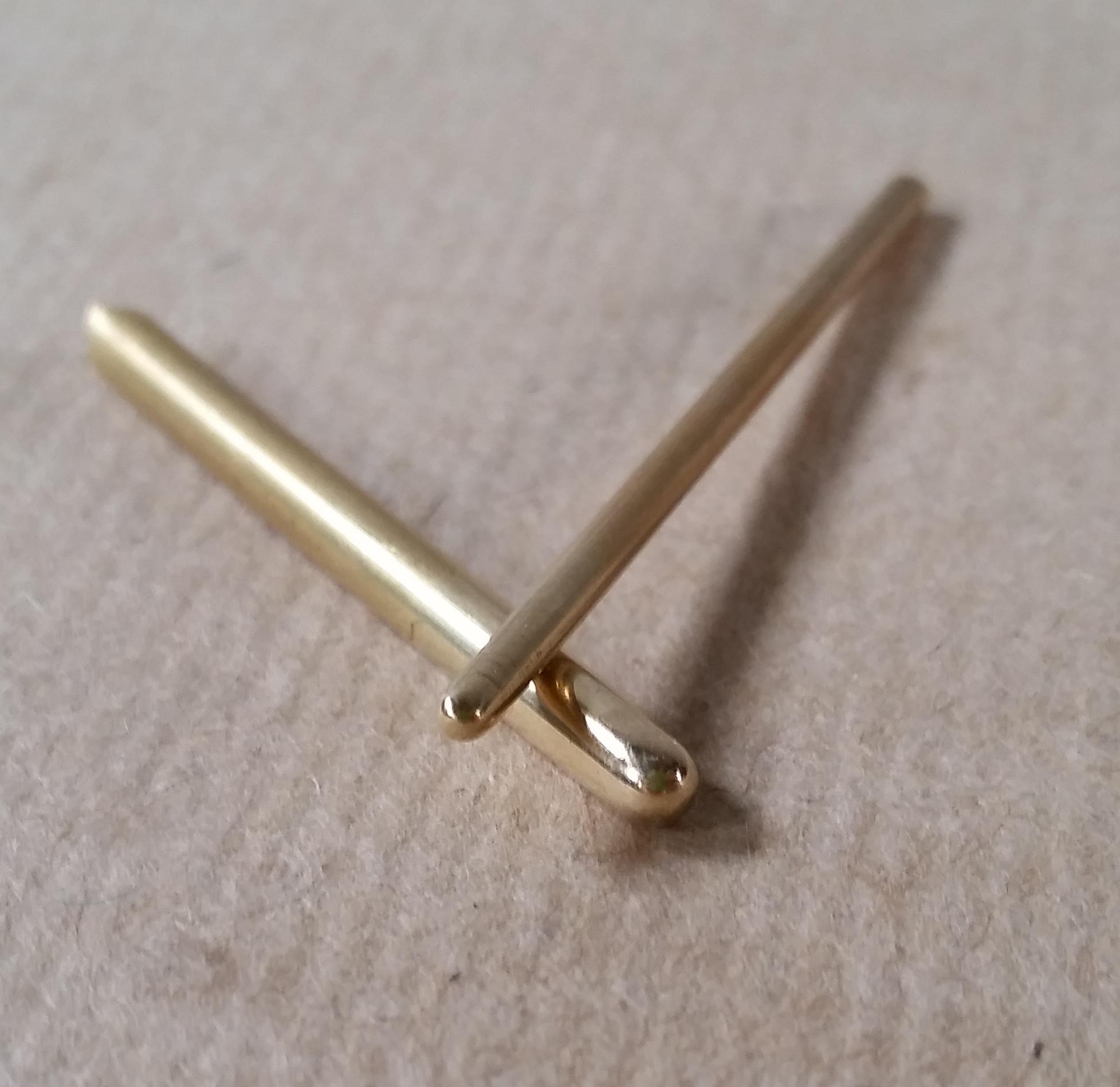
- A 2-3mm smooth round ended object to do the embossing*
I took pieces of 3mm and 1.5mm brass brazing rod that I put into a drill and rounded the tips with sanding paper, but you can even use something like the point of an RCA jack.
Disassemble the Soundbox:
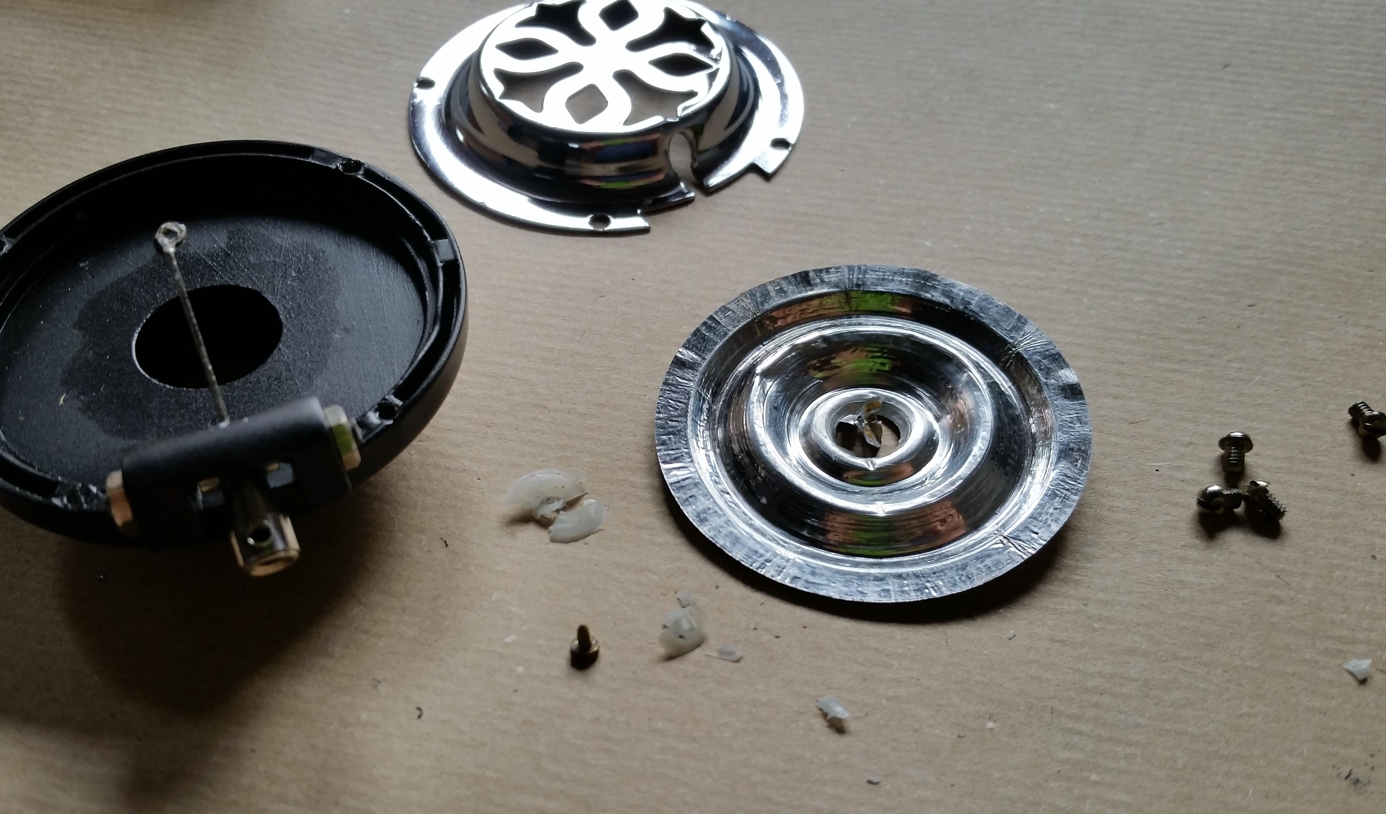
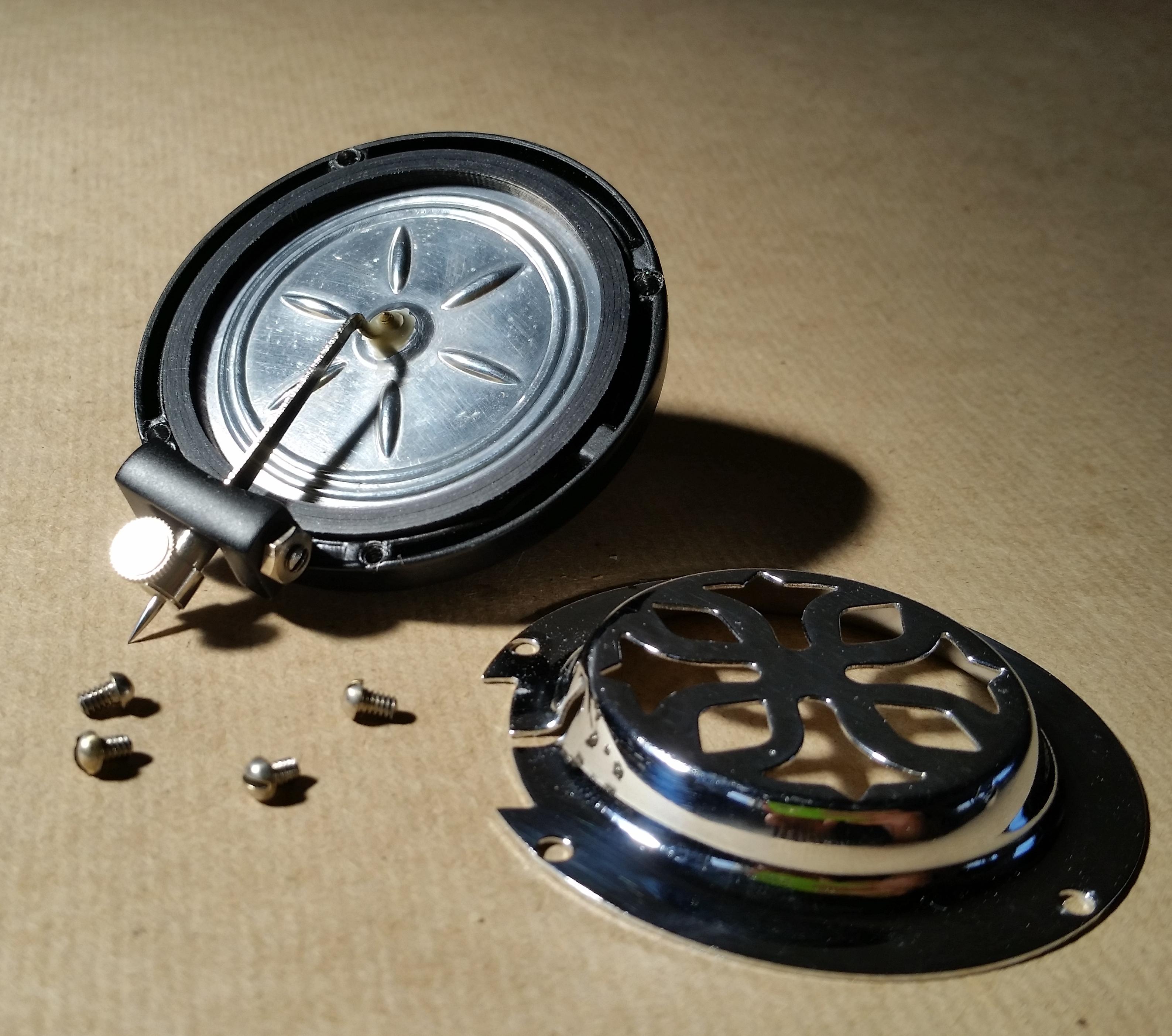
First we need to disassemble the soundbox to get all of the dimensions to design our diaphragm.
This will rely entirely on the model of your gramophone but most are assembled mainly the same.
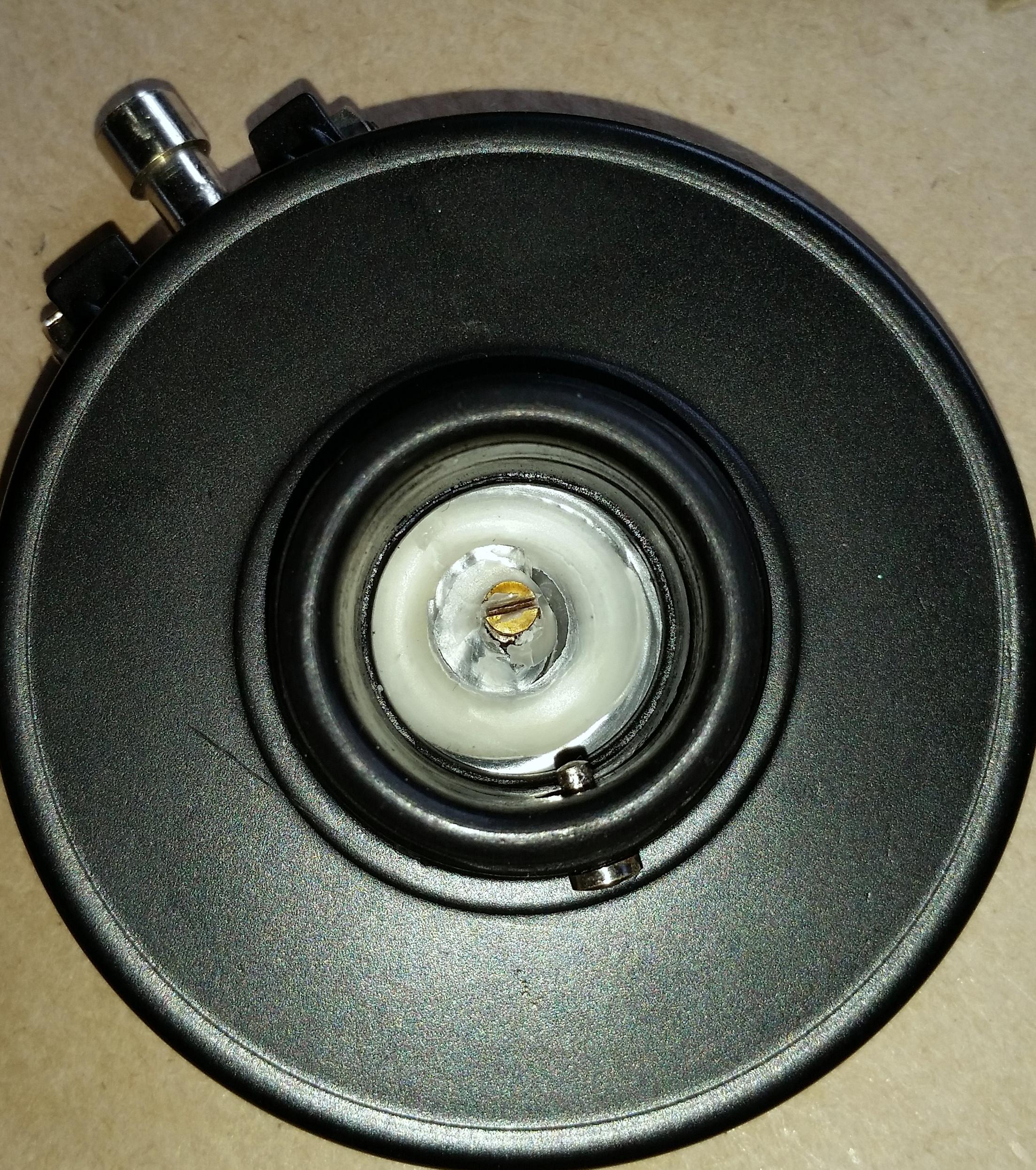
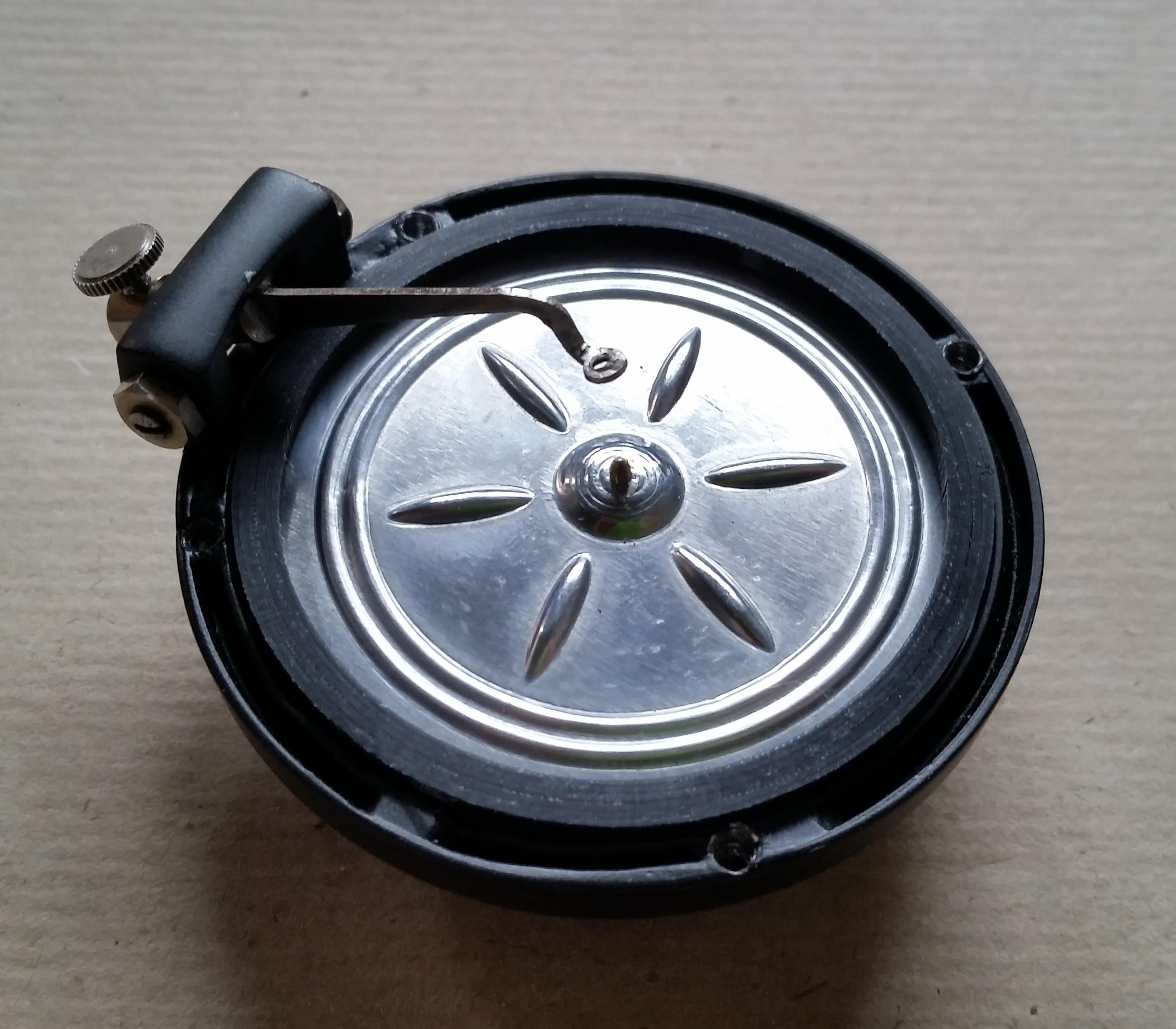
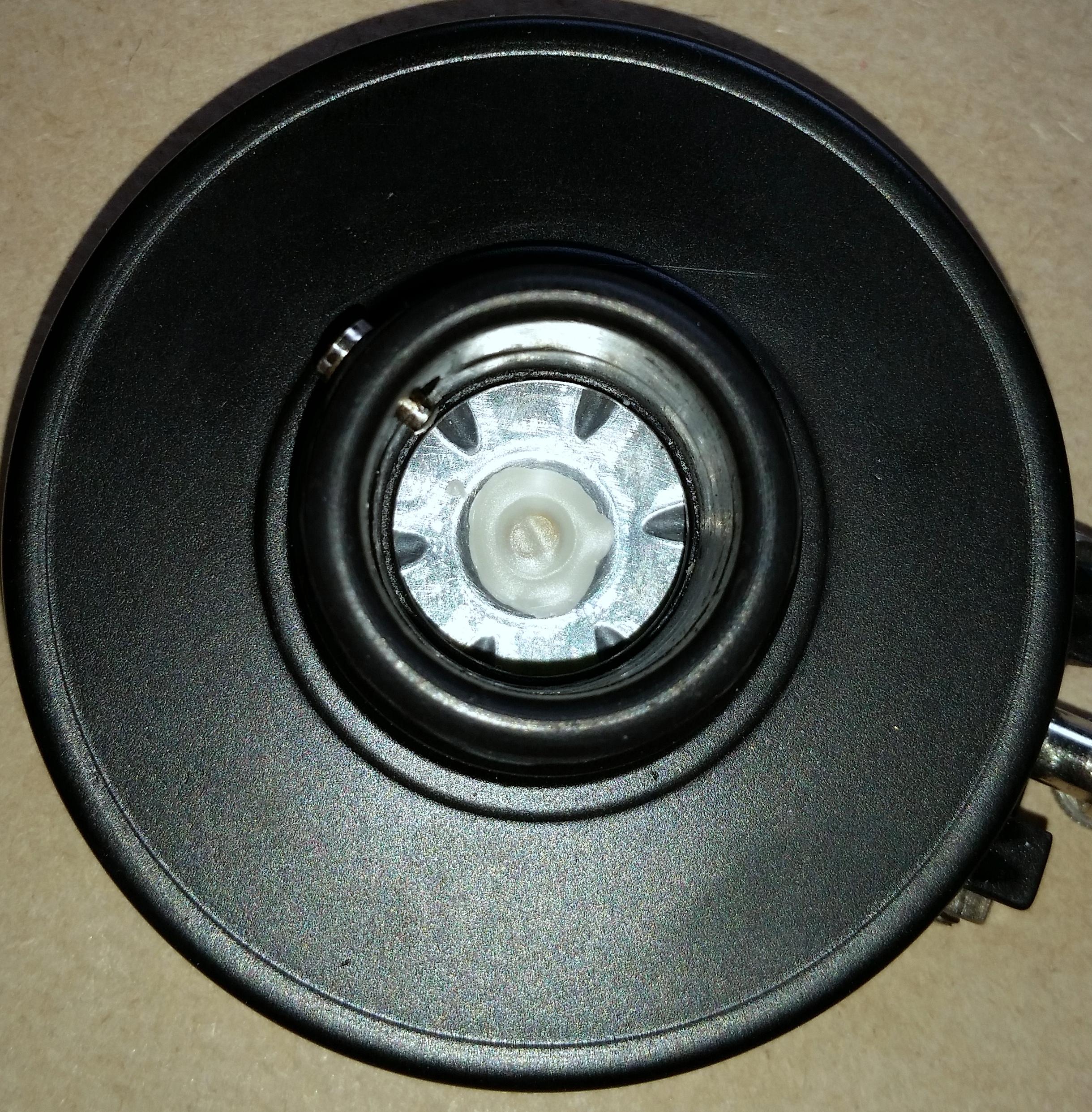
I started by loosening the 4 screws that holds on the front protective grill and removed it, next if you look in the hole at the back of the soundbox you should see a small screw that will most probably be covered in yellow wax.
Remove this screw to free the diaphragm, unfortunately when I took out the diaphragm I saw that the rubber surround that holds it in place and keeps it from rattling turned to dust with the slightest touch so I will also need to find/make a replacement for that.
Design the Die(Mold):
In this Instructable I will be using Fusion 360 to design the die.
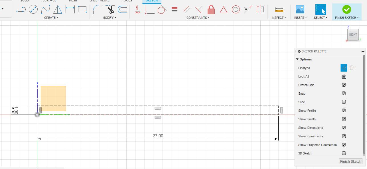
- Using the measurements of the diaphragm (most are 51mm and I made my die 54mm) that you removed we can start by making a bounding box, I created a rectangle that's 27mm wide and 1mm high and changed it to construction lines.
- Within this box we can create our design (you will only be creating one half of the diameter), now you can go wild.
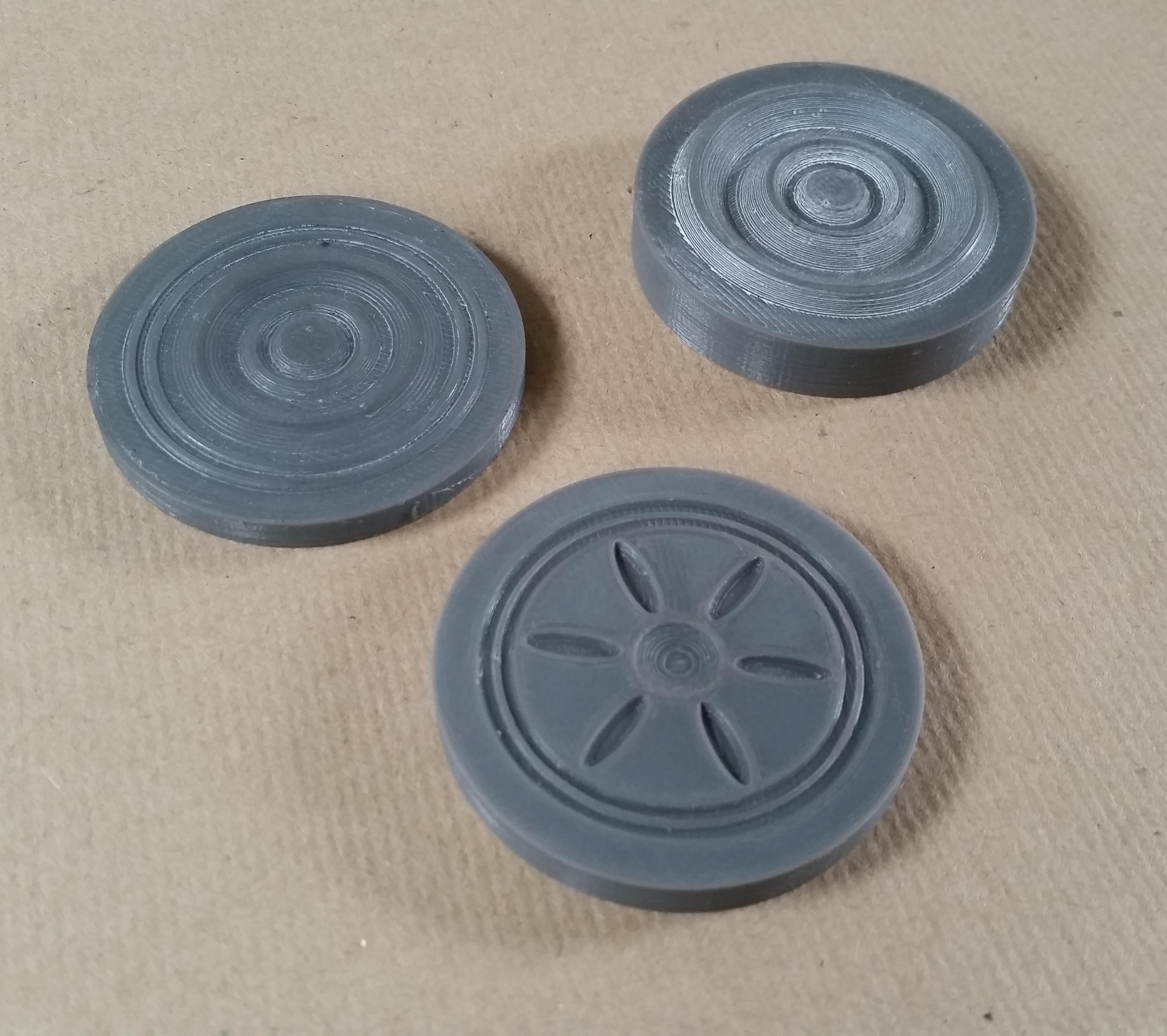
- I have already created three different designs and continue to think of more, the design of your diaphragm will have a direct impact on how your gramophone sounds so go ahead and experiment.
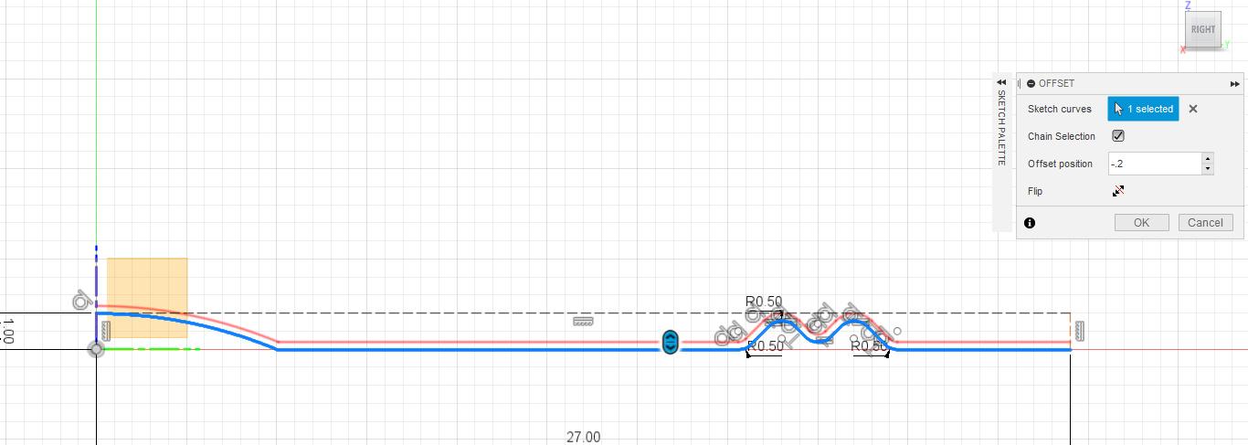
- Once you have your sketch finished offset it by the thickness of your aluminium and close the two sides that are now open on the sketch.
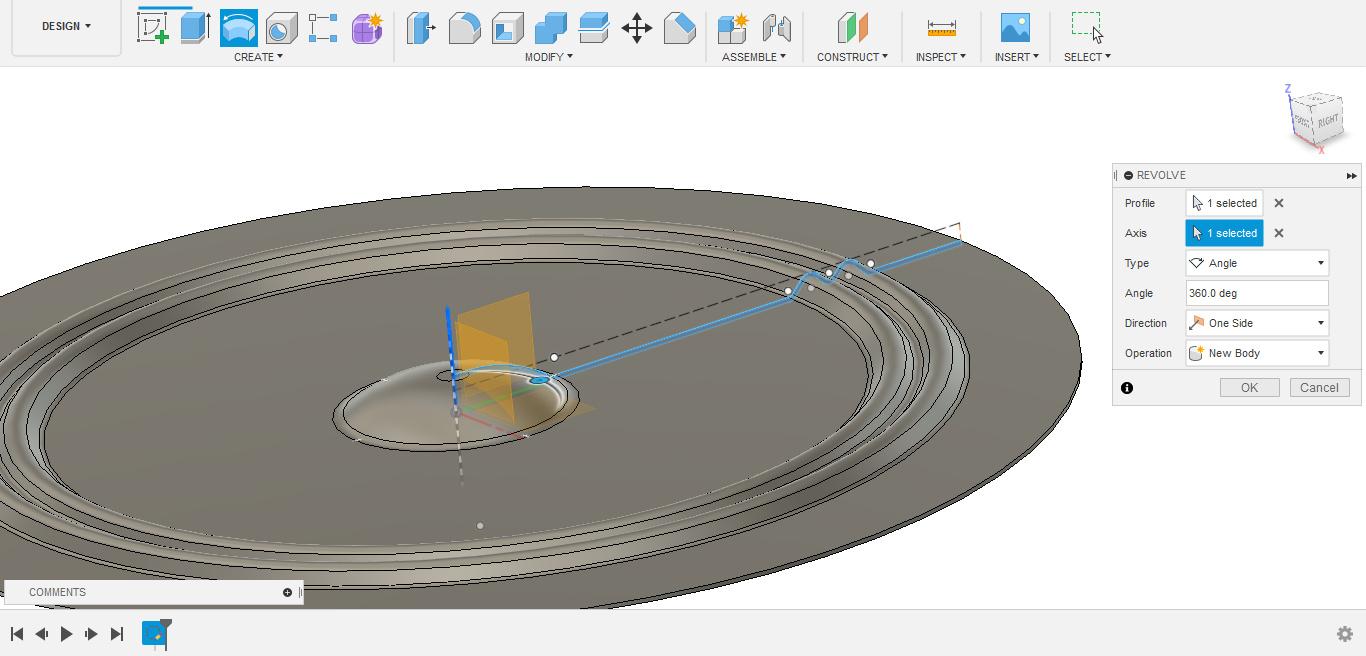
- Now we can use the "Revolve" feature and select the sketch you've just created, this will revolve the sketch around a centre selected axis and give you your diaphragm.
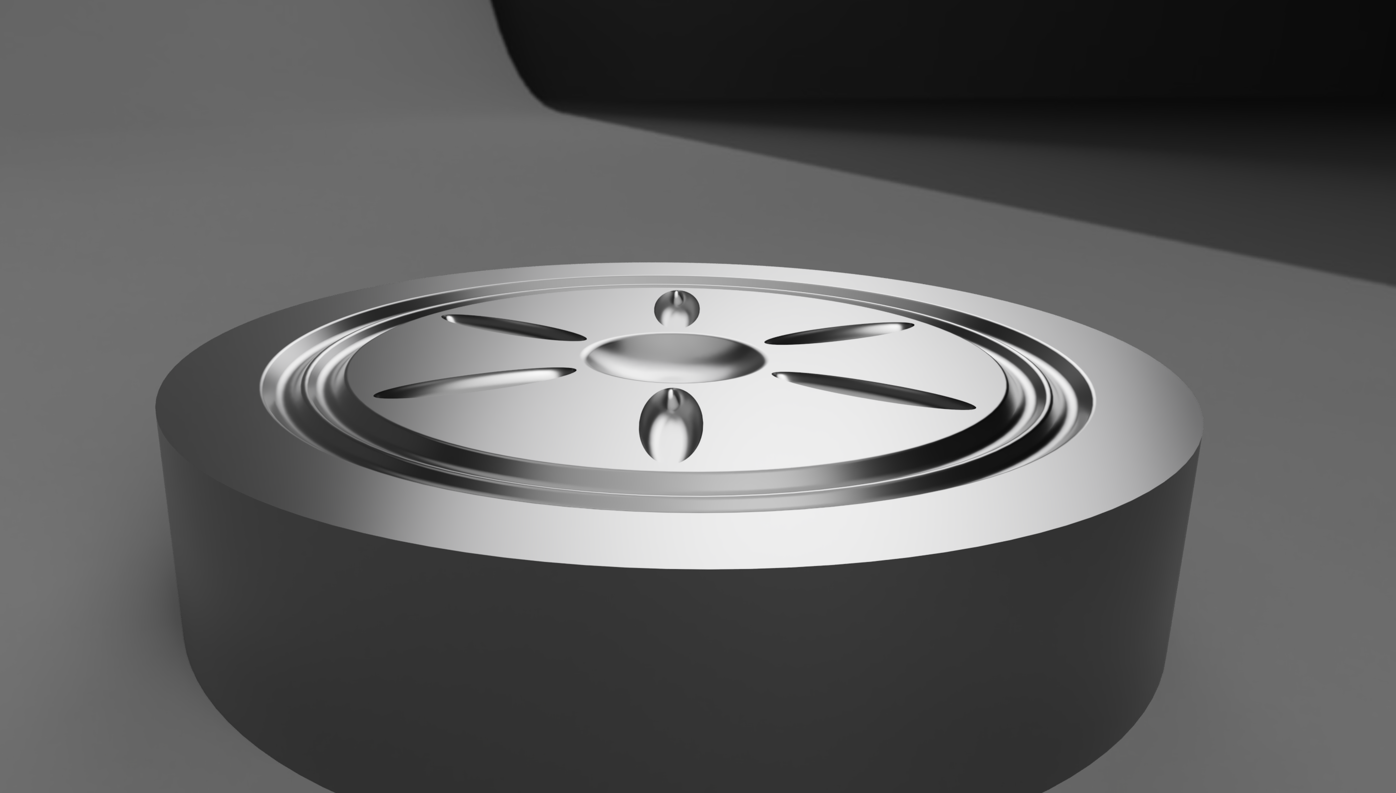
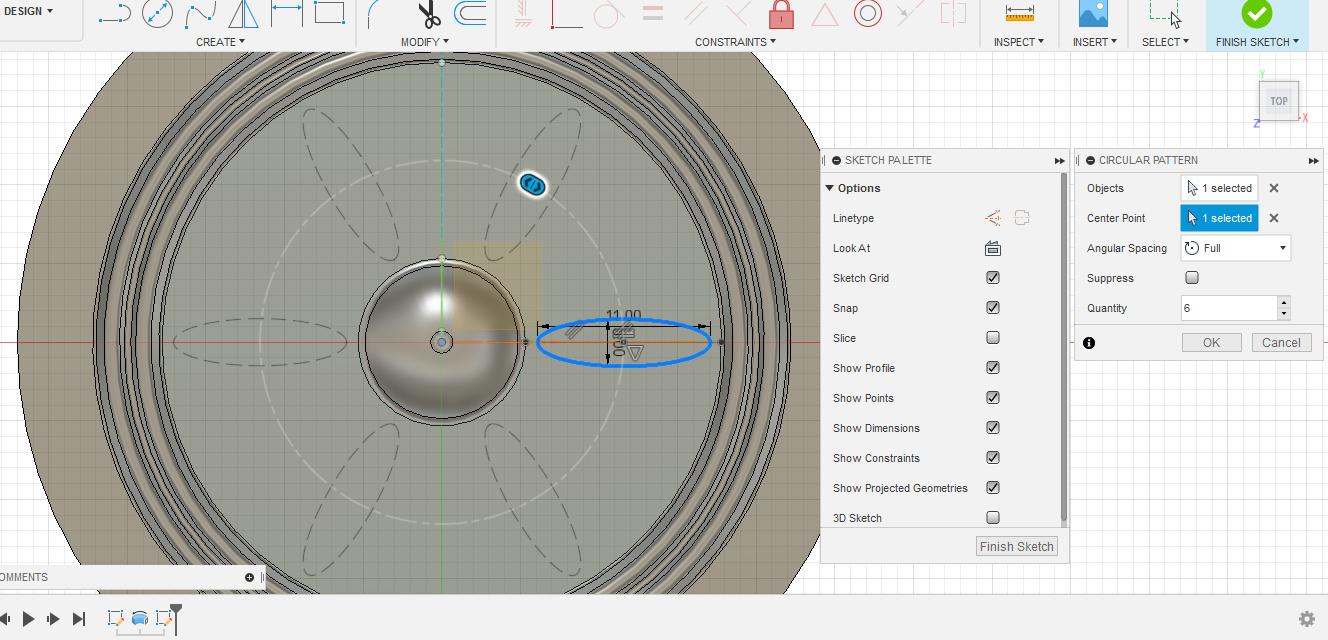
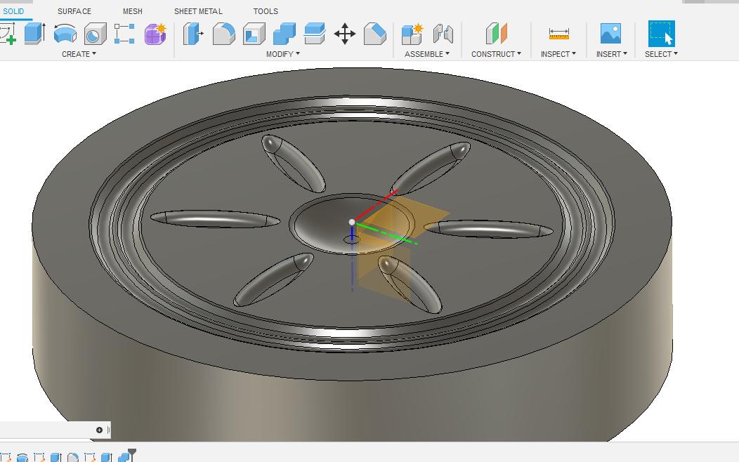
- After that I created a sketch on the top of the diaphragm and created a skinny oval that I repeated in a circular pattern.
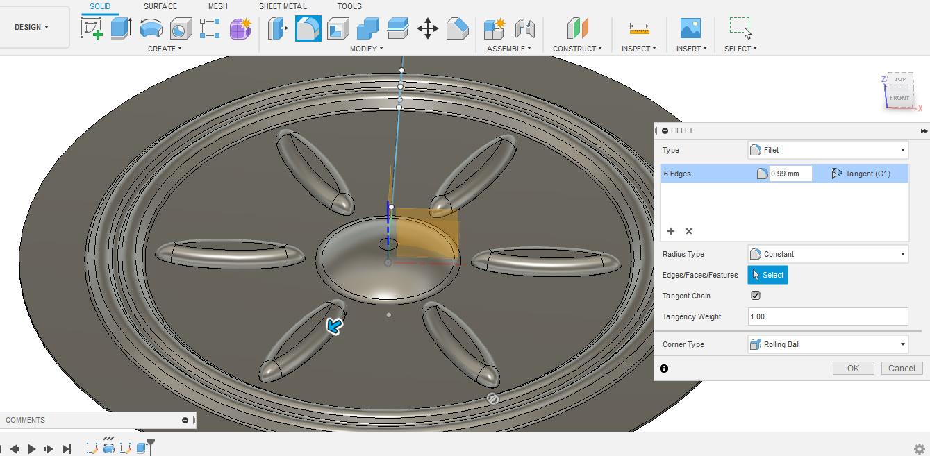
- I extruded the ovals by 1mm and rounded them with the fillet tool.
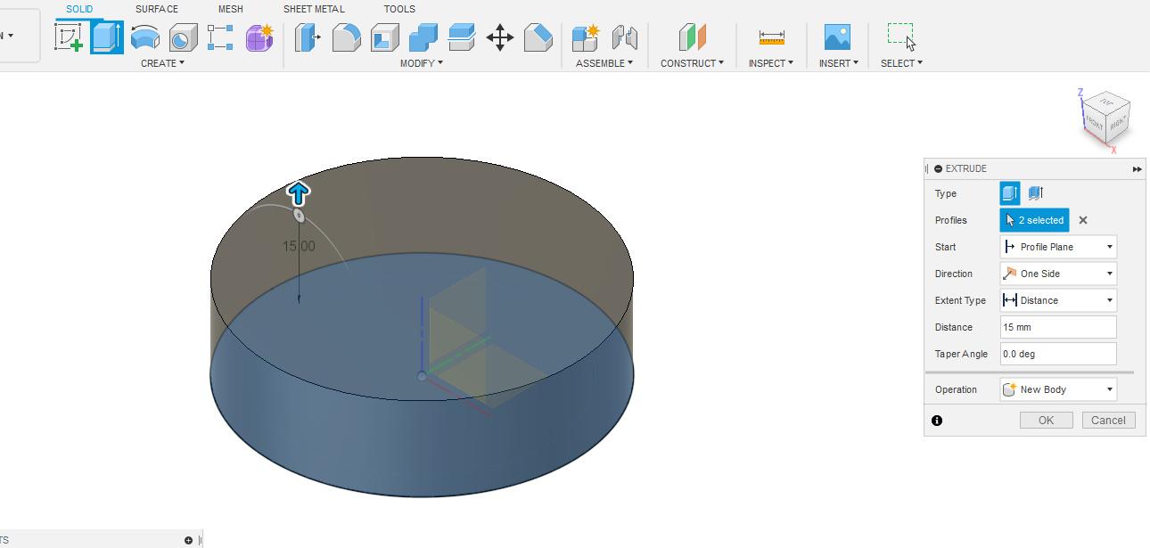
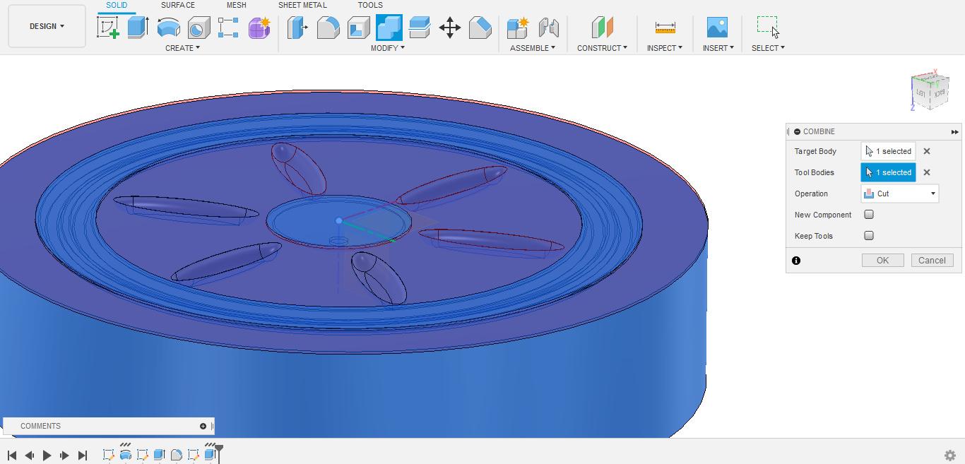
- Now in order to create your die we need to cut this design into a solid body, to do this I extruded a 15mm circle under the diaphragm.
- Next use the combine tool and select the circle as the target body and the diaphragm as the tool body and set it to cut.
- You should now be left with your die that can be exported as an STL or 3MF ready to be printed.
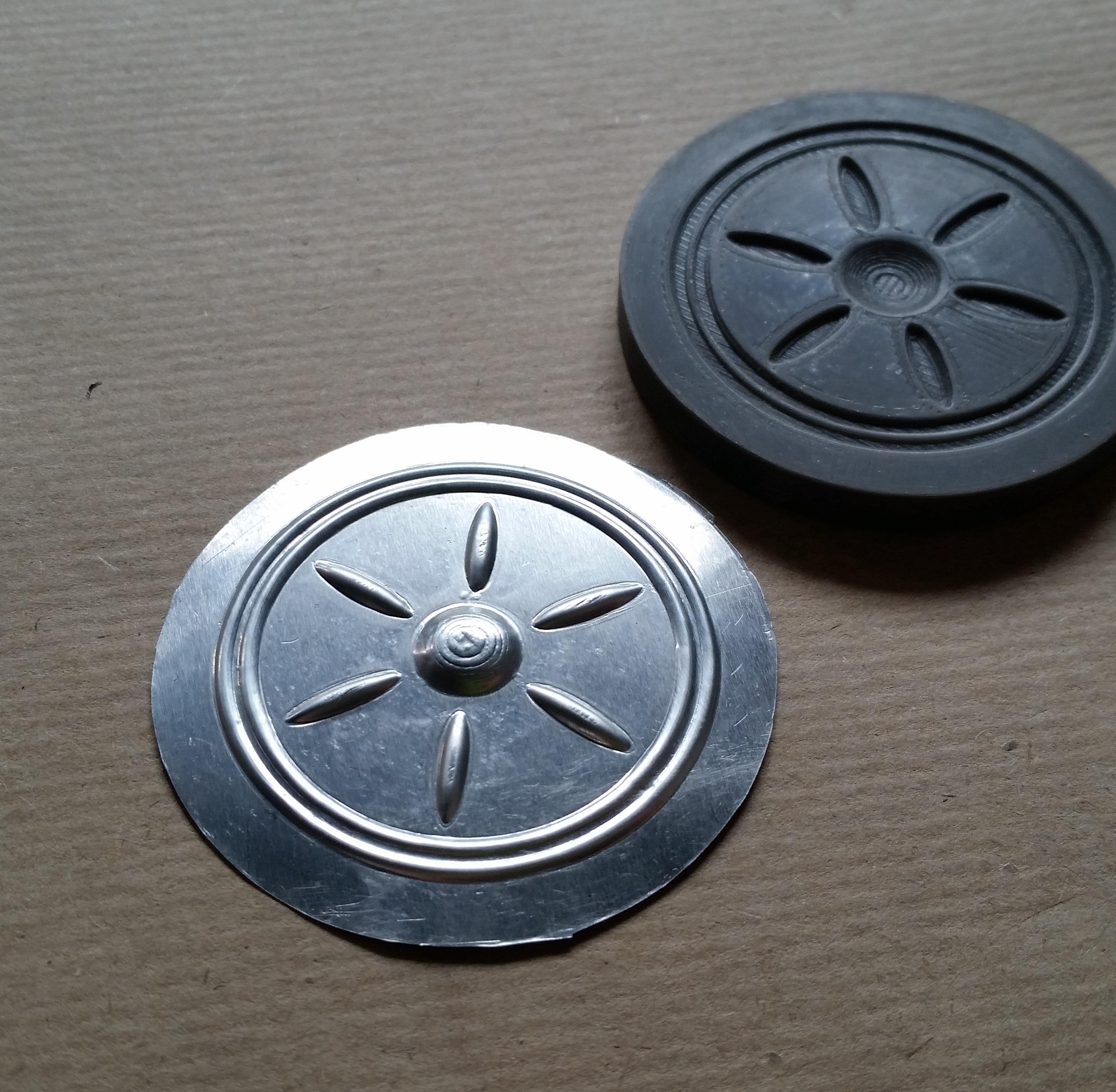
Print:
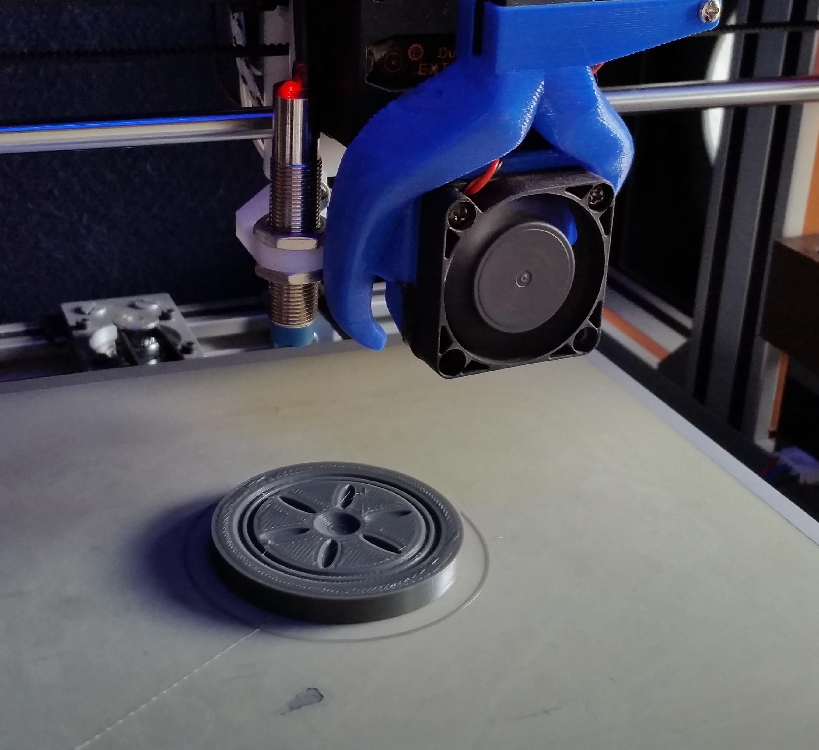
Now that we have our embossing die designed we can start printing it.
To get a good smooth print I decided to use PLA filament as it is the easiest to get smooth prints with.
My print settings are:
Material: Sunlu PLA
Layer height: 0.16mm
Speed: 30mm/s
Temperature: 220/60
Cooling: Off
Post Processing:
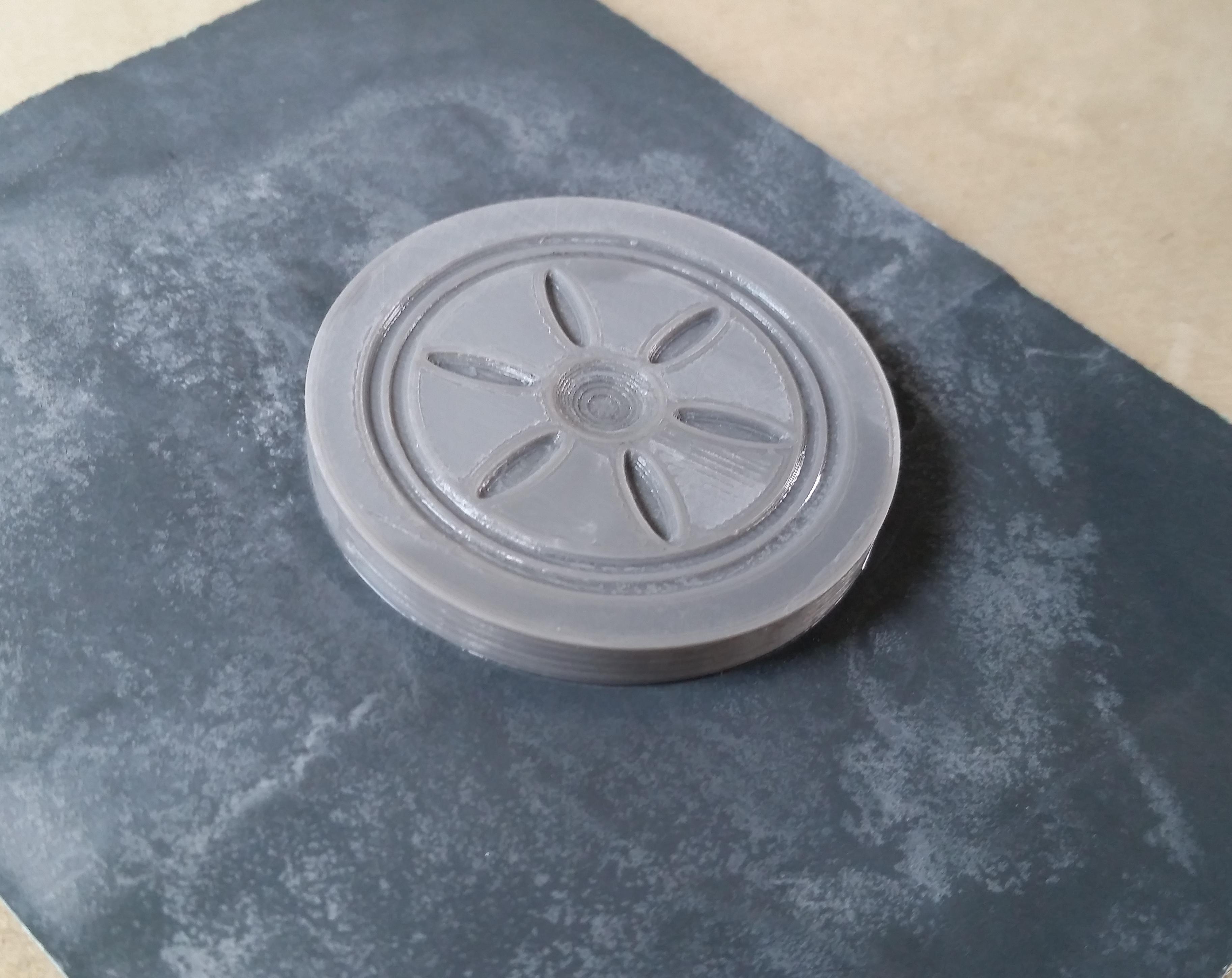
After our die is printed we need to smooth it out a bit.
I first used a sharp knife to cut away any blobs left inside the grooves of the print, this is important as any sharp parts inside the grooves will damage your aluminium while embossing.
Next I took some wet 400 grit sanding paper placed on a glass plane and sanded the top of the die to remove any lines left by the printer, you want this as smooth as possible.
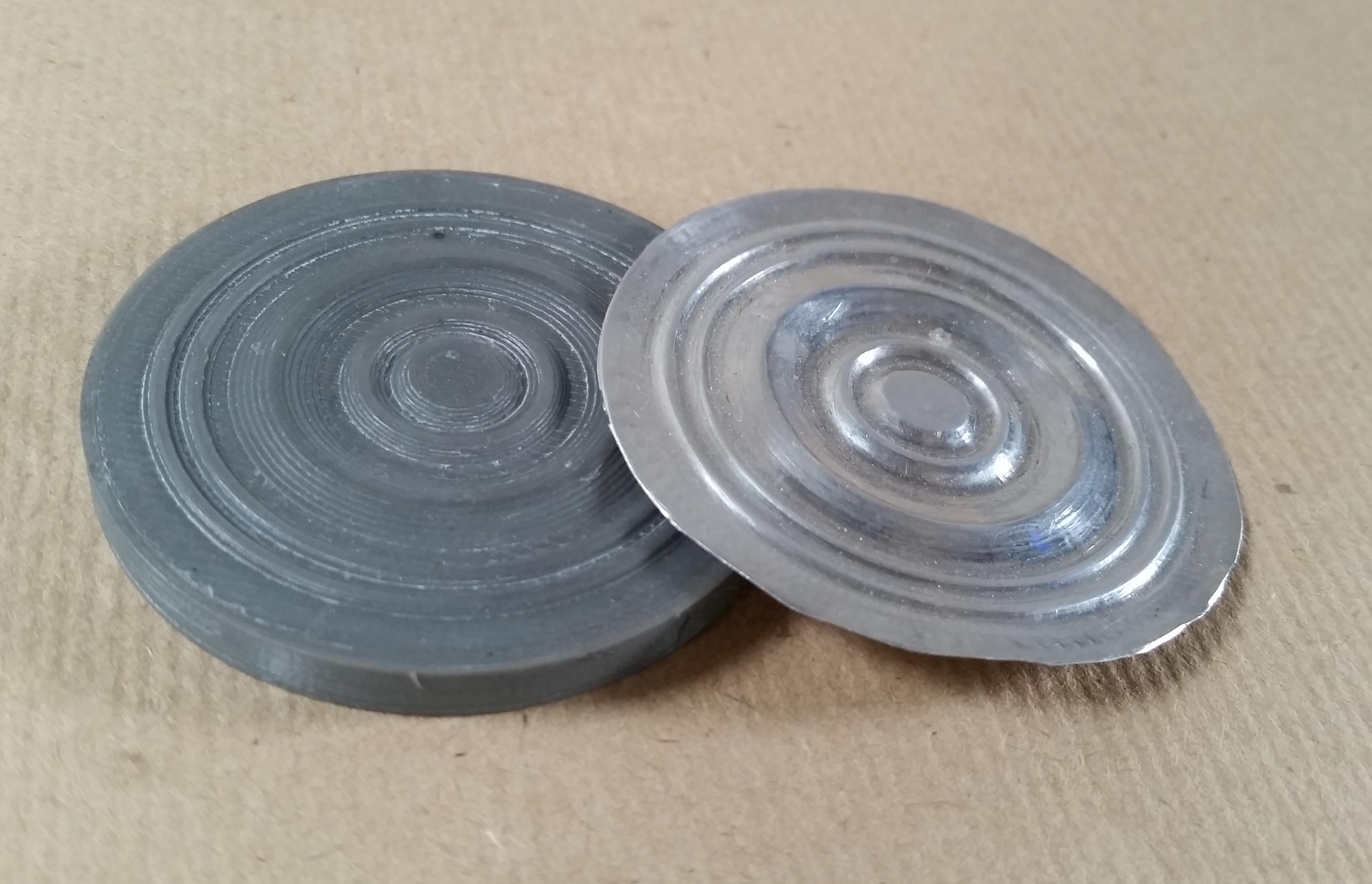
Embossing the Aluminium With the Die:
Now comes the fun part.
Place your die onto the aluminium piece then mark around it and cut it out, what I like to do is to score around the die with a sharp hobby knife and then by bending the aluminium slightly back and forth your shape should break free.
Now place the cut piece of aluminium onto the die and rub over it with your finger, this will create slight indentations that can be used as a reference on where to start.
Using your embossing tool start in the centre and gently start "rolling" the aluminium into the die, go slow too much pressure at once will cause a tear. We want to slowly stretch the aluminium into the die.
TIP: If you are having trouble with your embossing tool "grabbing" onto the aluminium you can add some oil to lubricate it.
Once you are done with the centre you can start moving outwards.
I first do the entire die with the 3mm rod then move to the 1.5mm just to get the sharper details.
Smooth It Out:
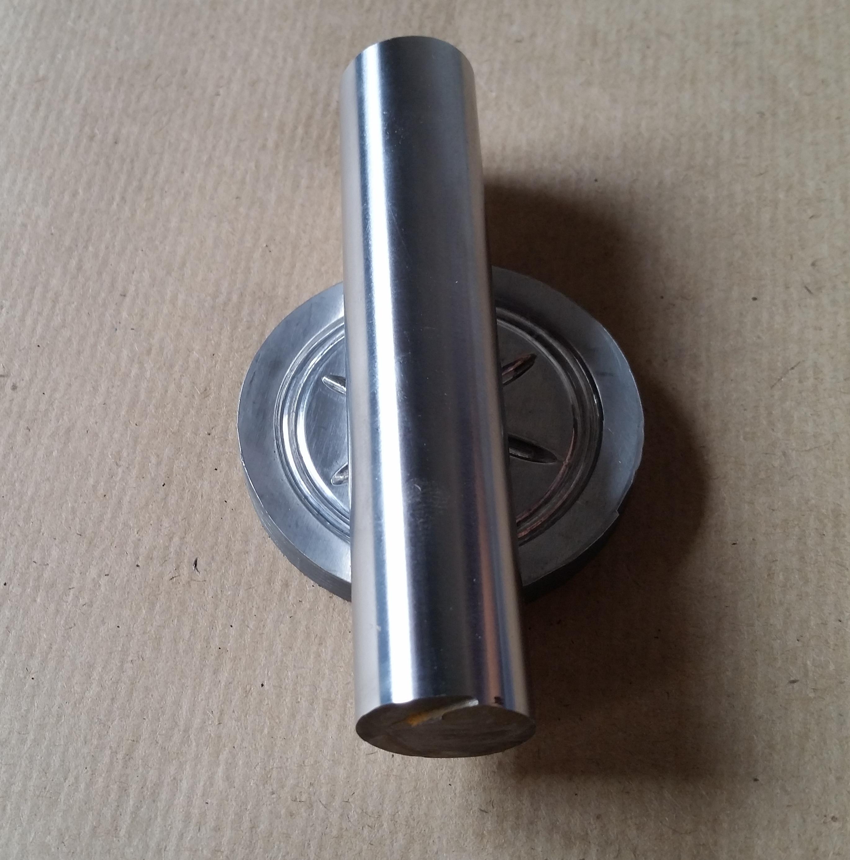
Now we are going to take the metal rod and roll/scrape it over the die a few times in different directions.
Doing this will flatten out the diaphragm getting rig of any wrinkles and it will also work harden the aluminium giving you a much stiffer end result.
Making the Hole:
We will now need to make the hole where the needle arm will attach to.
To do this I started with a sharp needle and pierced a small hole through the centre of the dome, I do this from the back to prevent it from deforming from the pressure.
Next you can use a small drill or like me a Dremel engraving bit to enlarge the hole until the screw from the original fits through.
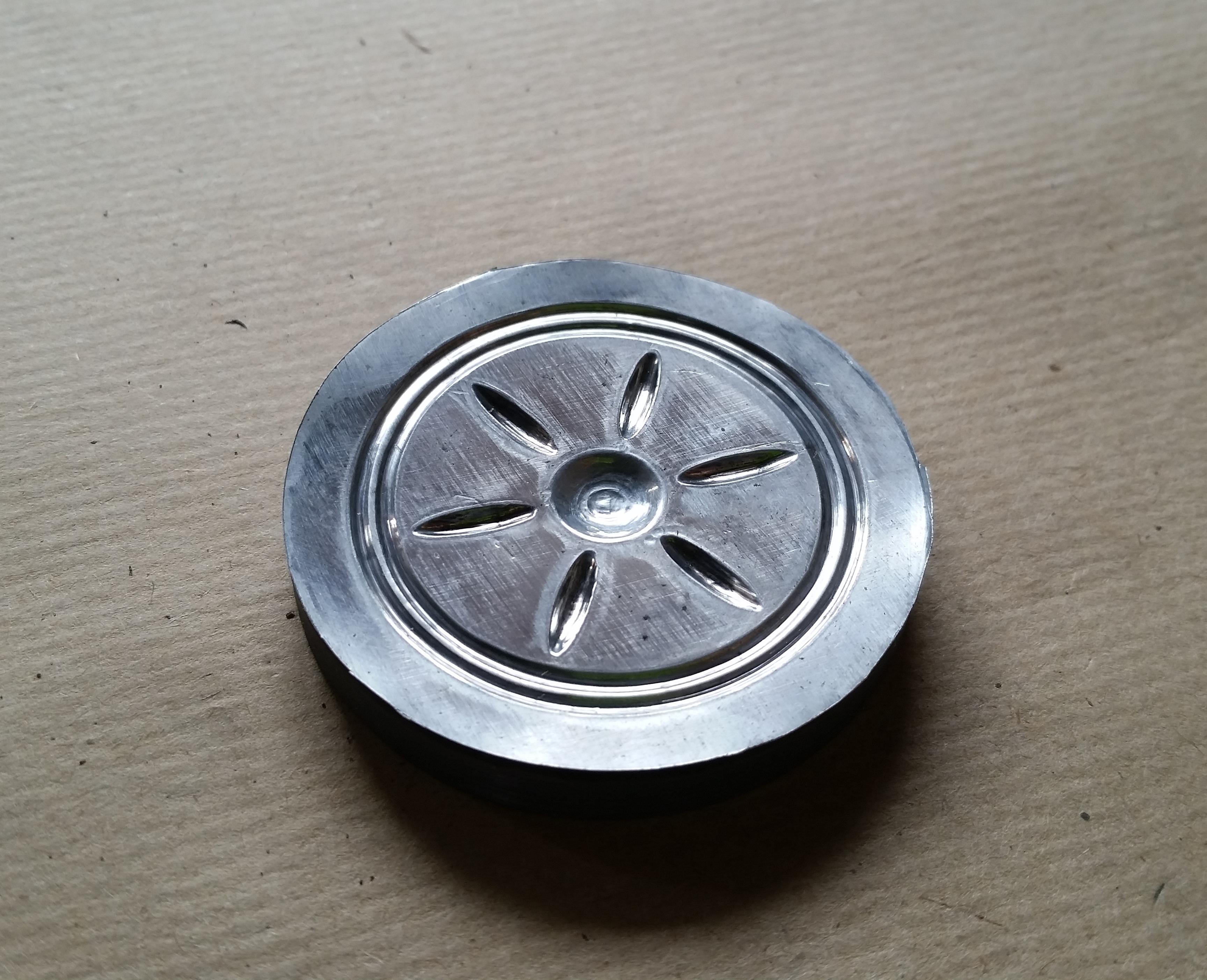
Make It Shine:
This step is optional but it does look a lot more professional in the soundbox if it's nice and shiny.
Apply some automotive compounding polish or metal polish to the top of your diaphragm and with a bundled up soft cloth start buffing in small circular motions.
It might look fragile but the embossed aluminium can take quite a bit of pressure before you damage it.
I had to reapply polish about 3 times to get a nice surface finish.
Replace the Diaphragm:
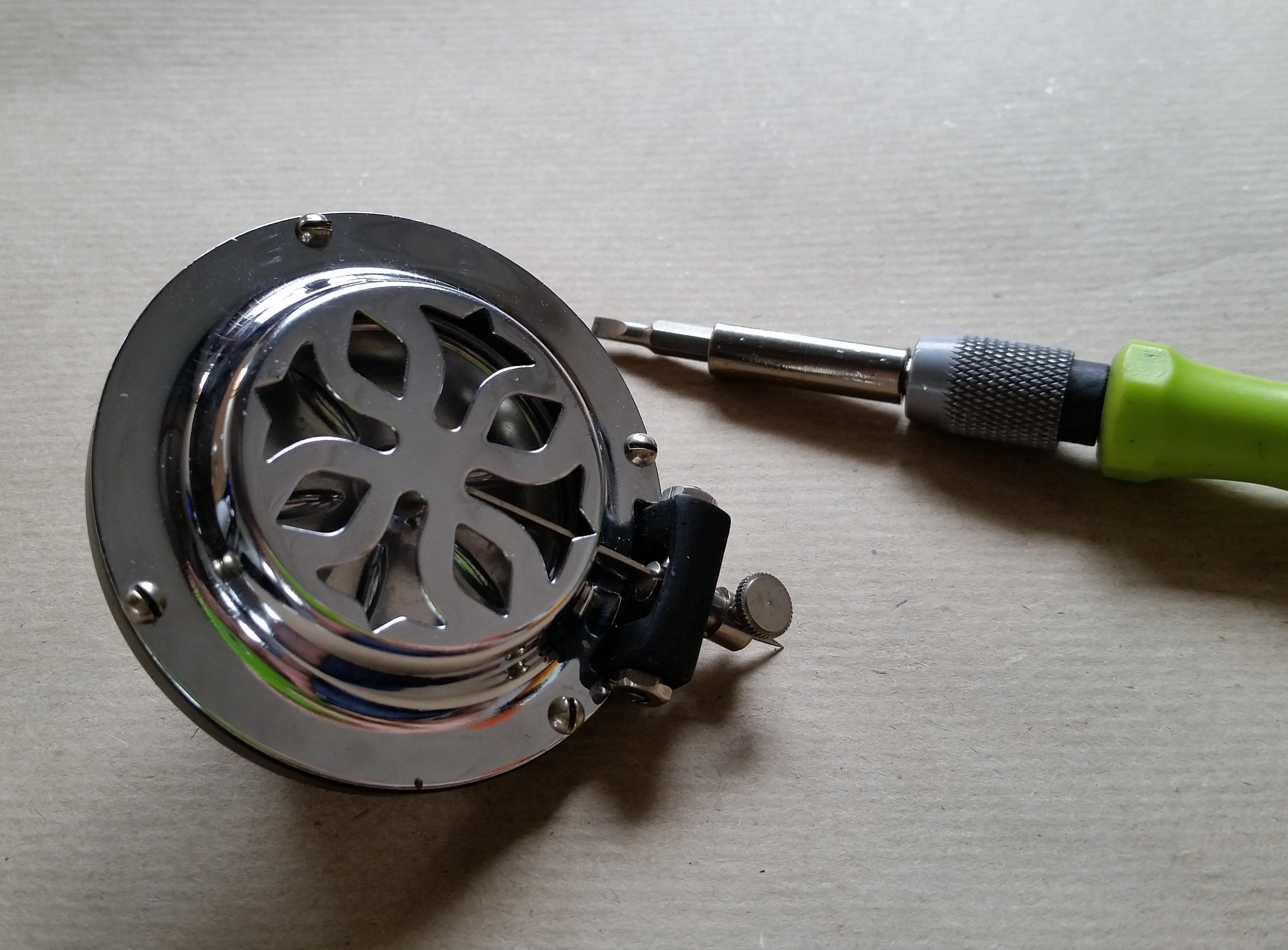
We are now finally ready to start the reassembly process!
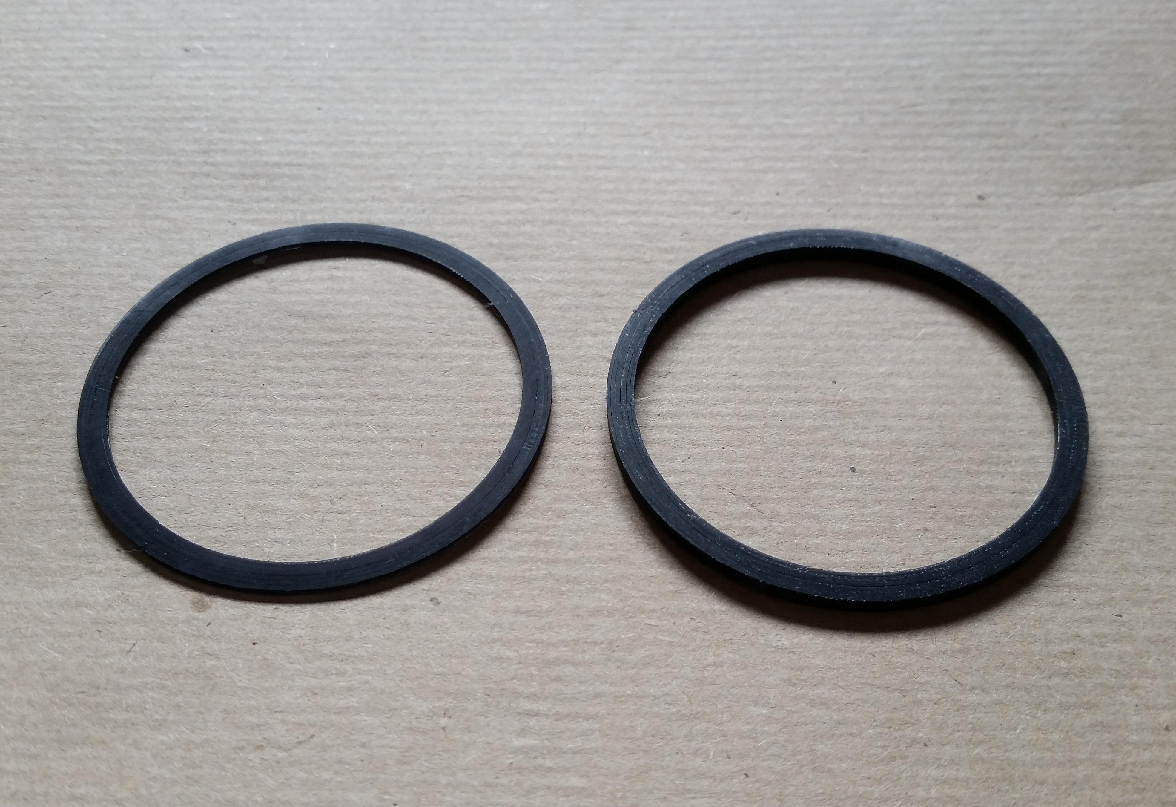
First because my diaphragm surround was now dust and no longer rubber I decided to print two replacements from elastic TPU filament. The ones I made to fit mine were just two 3mm wide circles, the bottom one was 1mm thick and the top one was 2mm to get a nice tight seal.
If you don't have suitable filament you can also visit your nearest auto or hydraulic supply store and let them search for two O-rings that's the correct size.
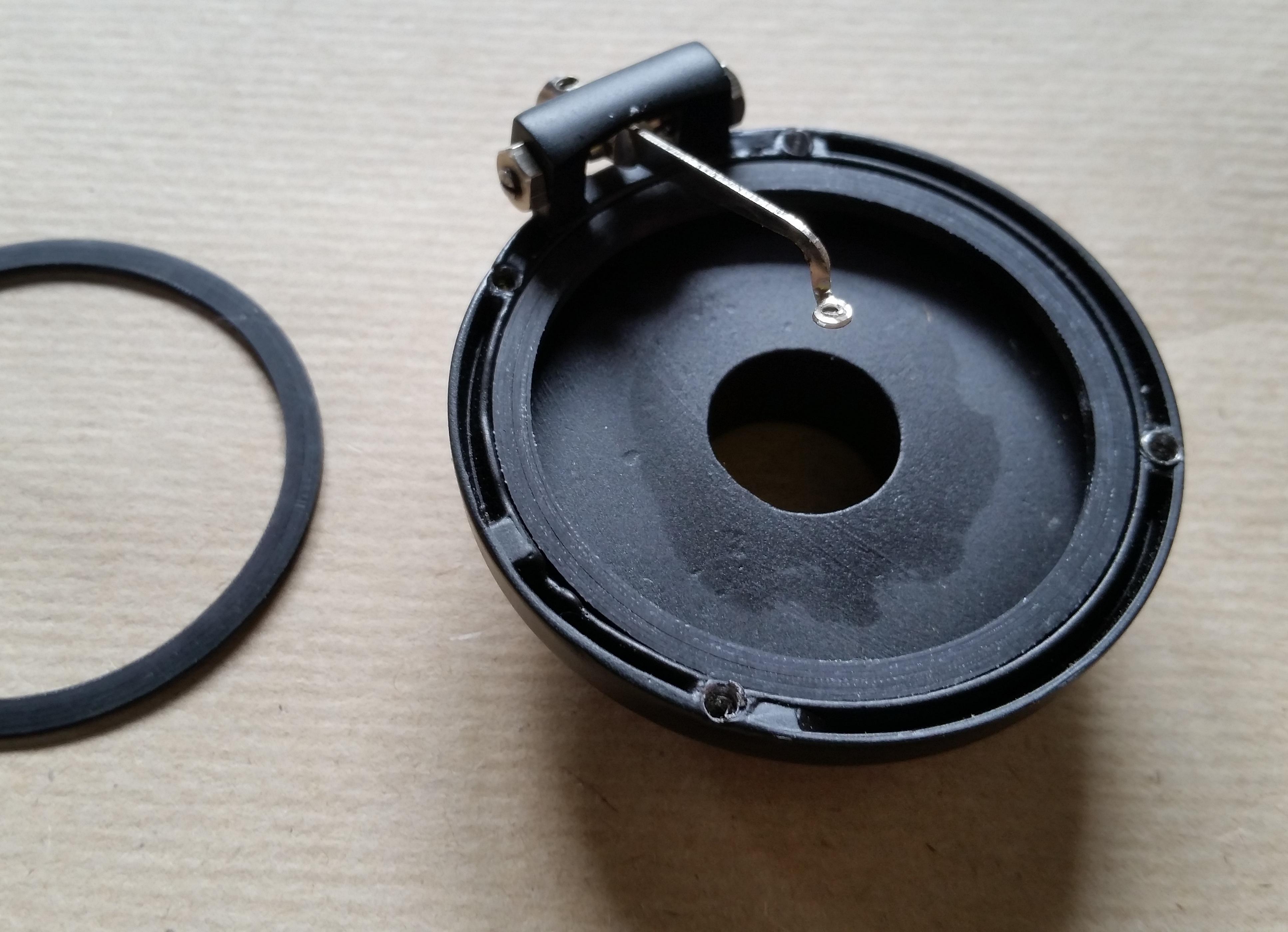
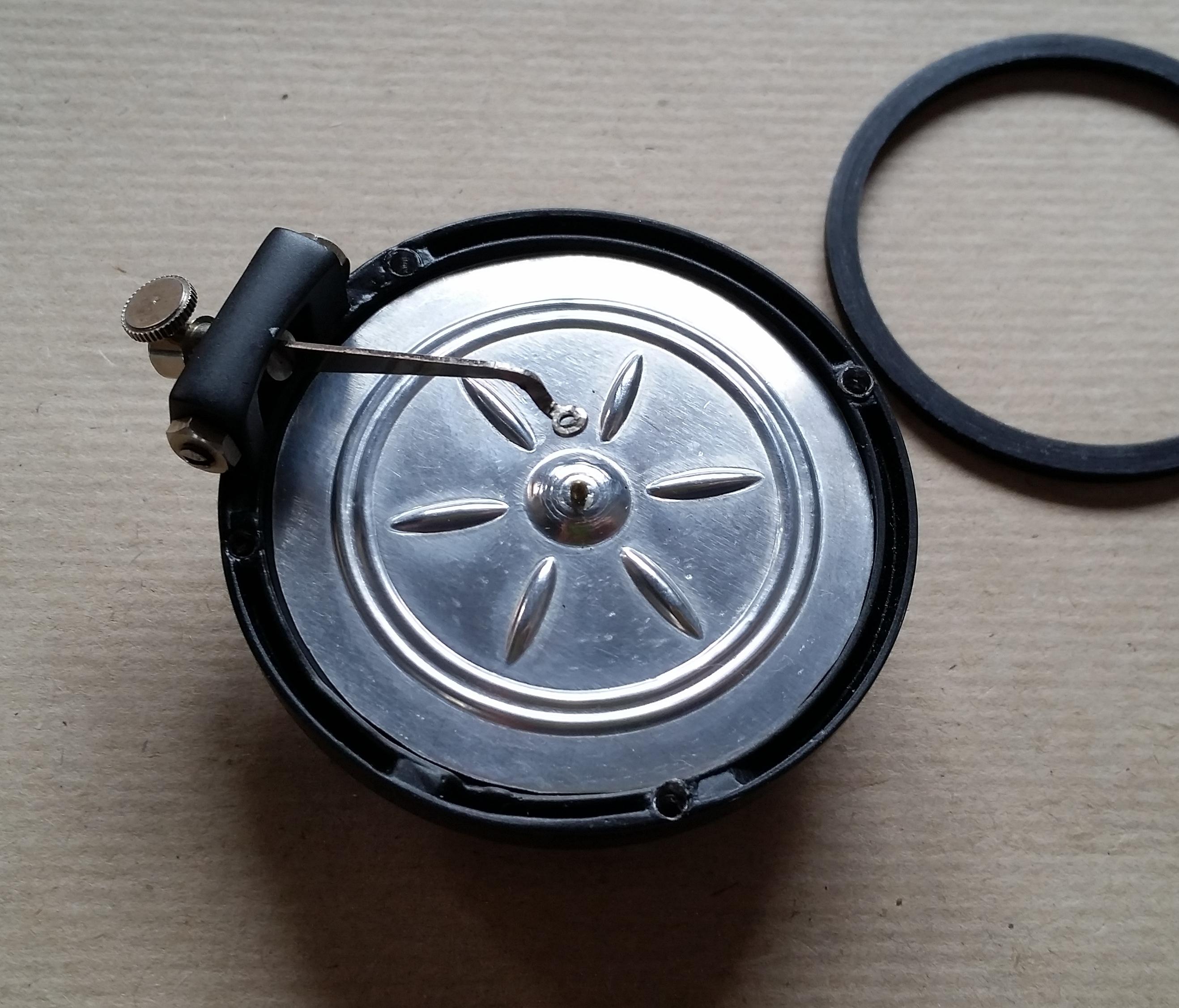
Next I inserted the first 1mm seal into the soundbox body, ontop of that I put the new diaphragm and next the second seal.
Now lower the needle arm onto the diaphragm and make sure it is centred onto the hole, then screw in the bolt from the back.
-Be careful when fastening the bolt as the thread is very fine and easy to damage-
Wax:
Now to keep the arm from vibrating on the diaphragm creating unwanted distortion and to keep the bolt from loosening we need to apply some molten wax.
For me the easiest way to do this is by heating up a pair of fine nose tweezers on a flame and then dipping it into wax, it will then wick up a small amount that is easy to place on the area.
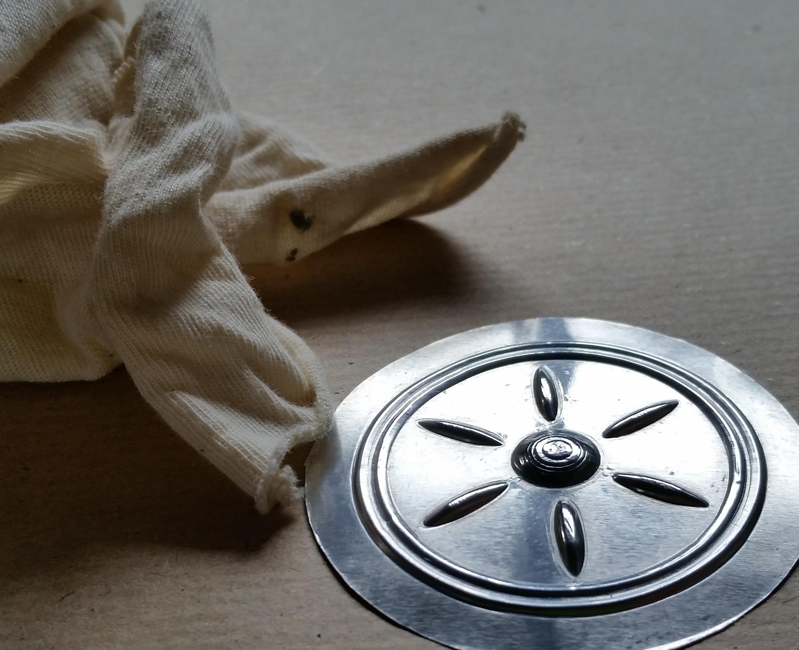
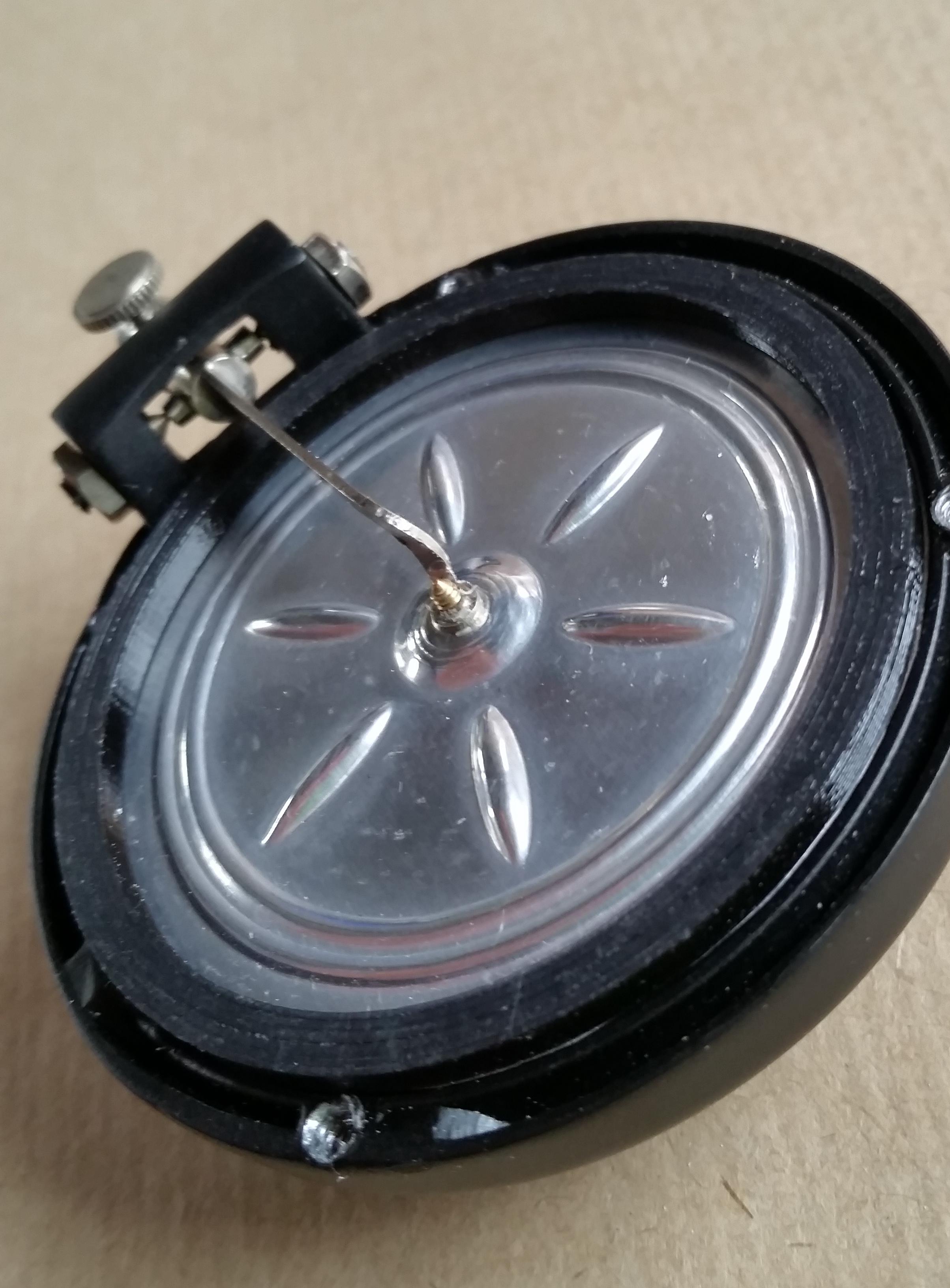
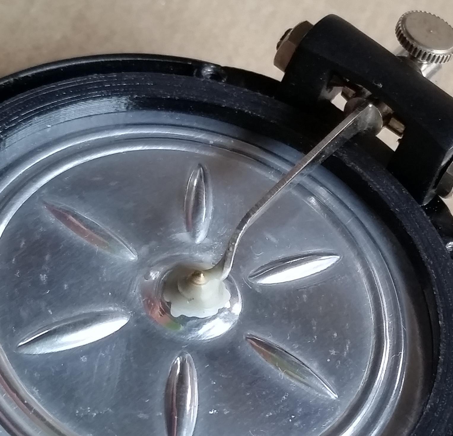
You want a drop where the needle arm makes contact with the diaphragm and on the bolt on the other side as pictured,
After putting a drop on both sides I heat up the tweezers again and then smear the applied wax around making sure it seeps in between the arm and diaphragm.
Now you can finish the assembly by reattaching the top protective cover.
Enjoy!
Now you can enjoy your gramophone again!
If you experience any unwanted distortion you can add more wax onto the diaphragm to dampen it.