Remote Controlled Timer With NodeMCU
by joosthuter in Circuits > Arduino
1206 Views, 2 Favorites, 0 Comments
Remote Controlled Timer With NodeMCU
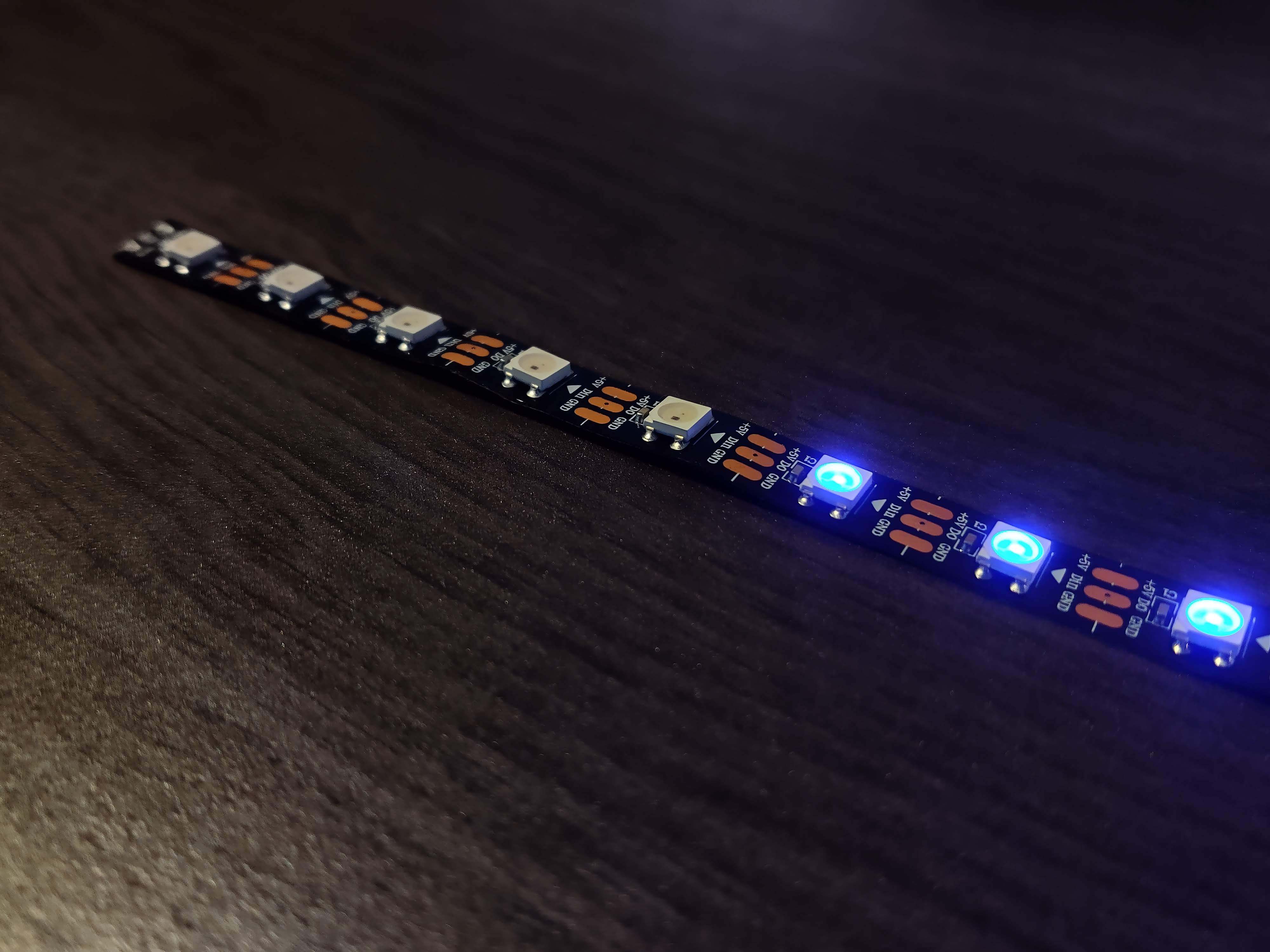
Here we're gonna be creating a timer using a NodeMCU and Adafruit. We are going to be displaying our timer with a LED strip and we'll be able to control it using our phone or computer!
Our goal:
Create a timer using a LED strip that we can: start, pause and reset using our phone or computer.
Downloads
Supplies
Hardware:
Libraries:
- Adafruit_NeoPixel.h
AdafruitIO_WiFi.h
Other:
- A decent WiFi connection
Let's Create a Feed in Adafruit!
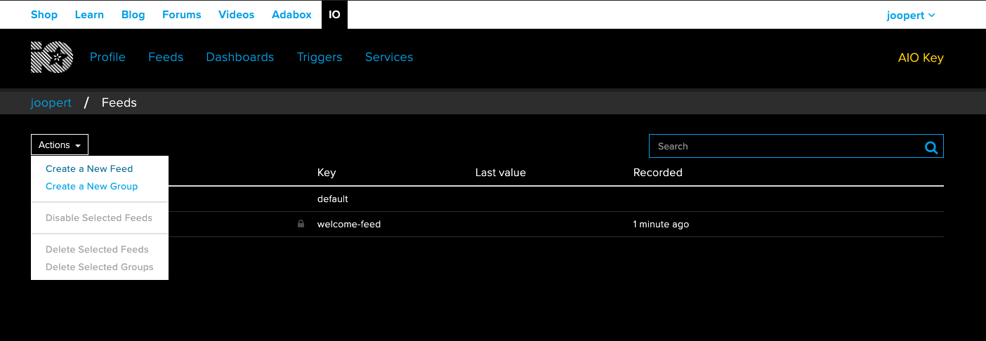
Now that we got everything we need, we're ready to start building! First of all we have to create a feed in Adafruit. Adafruit is a service that makes it really easy for us to connect our Arduino to the internet and make useful remote controlled features. If you haven't already, sign up for Adafruit.
Now let's create a new feed!
We can name our feed anything we want, I'm calling it 'timer'.
What a feed does is record everything we do in our dashboard (which we'll create in just a minute) and sends that data to our board, but that's something we'll look at once we have data to be sent.
Now Let's Make a Dashboard..
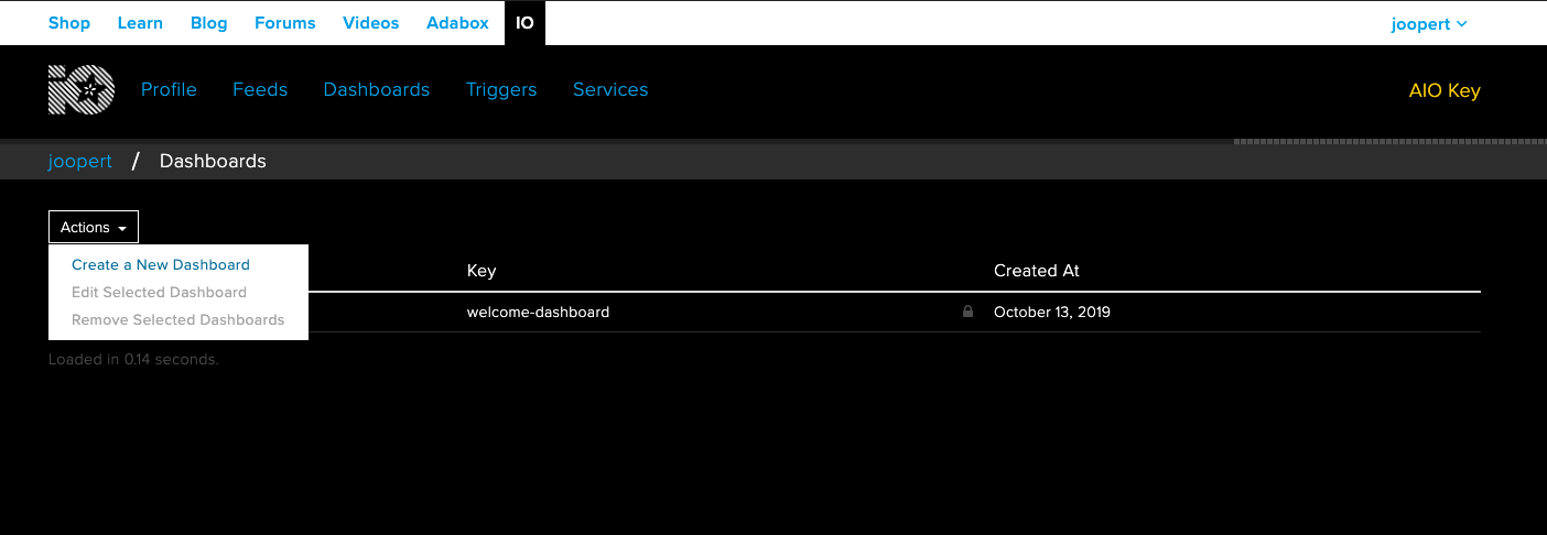
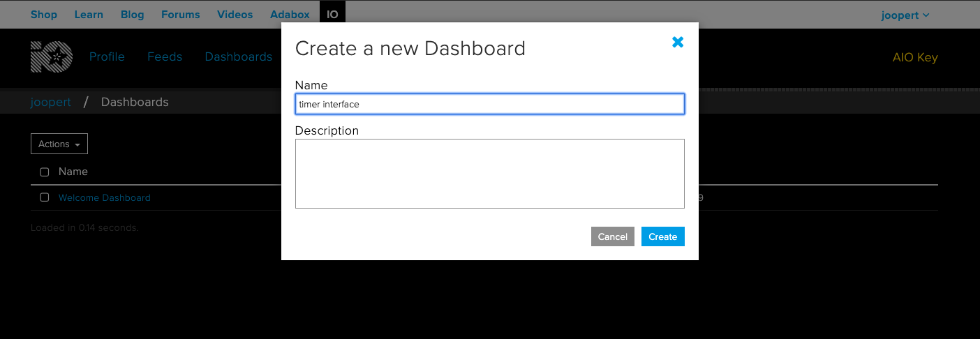
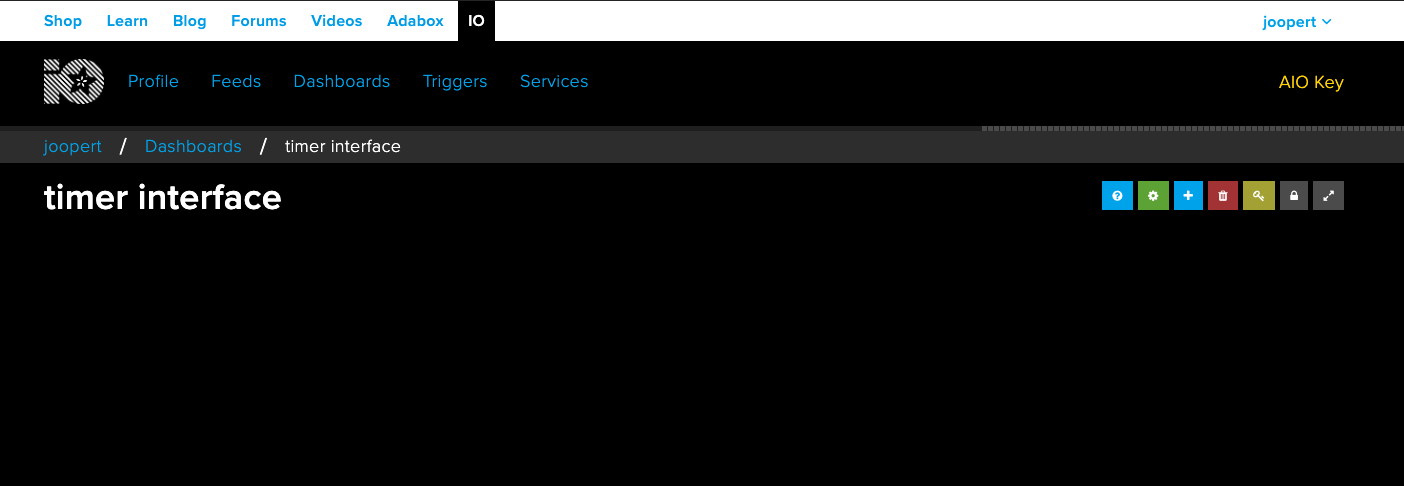
Now in the same way that we made a feed, we'll create a new Dashboard. I'll call my dashboard: 'timer interface' because that's basically what our dashboard will be: an interface with the buttons to control our timer.
Get Our Key

If we want to connect our Arduino to our feed we need to get our Adafruit key, this is your secret password that will make sure only you can connect to your feeds.
You can get your key by clicking the yellow AIO Key button in the top right of your screen in Adafruit.
Save this key somewhere, we're gonna need it later.
Don't share your key! Otherwise people with bad intentions could connect to your feeds and devices.
Open the Feed Read Example
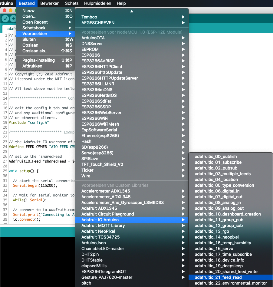
Now let's open our Arduino IDE and start the coding proces. First of all we need to have the Adafruit IO Arduino library installed.
Don't know how to install libraries? this is a great guide by Adafruit: Arduino Libraries
Adafruit offers a lot of pre-made examples for us to use and learn from. One of these examples is: adafruitio_21_feed_read. You can find this example here: File ---> Examples --> Adafruit IO Arduino --> adafruitio_21_feed_read
(excuse my dutch interface in the image)
Let's Set Up Our Connection
If you've succesfully opened the adafruitio_21_feed_read sketch you should be seeing 2 tabs in your sketch: adafruitio_21_feed_read and config.h. This sketch was made so that we can connect to the feed that we made in step 1.
To connect to this feed we need to fill in a few details about our WiFi and our Adafruit account,
Let's travel to config.h, here we'll fill in the following details:
Your Adafruit username:
#define IO_USERNAME "joopert"
Your Adafruit key:
#define IO_KEY "1234567890abcdefghijklmnop"
Your WiFi's name:
#define WIFI_SSID "MyWifi"
And your WiFi password:
#define WIFI_PASS "aVerySecretPassword"
Now let's go back to the adafruitio_21_feed_read tab and fill in:
Your Adafruit username... again:
#define FEED_OWNER "joopert"
And finally your feedname (from the feed we made in step 1):
AdafruitIO_Feed *sharedFeed = io.feed("timer", FEED_OWNER);Check the Connection to Adafruit IO

To check if the steps we took before have been executed correctly, we are going to upload our sketch to the NodeMCU. If you open your serial monitor, it should look something like the picture above. First the serial monitor is showing you that it's trying to connect to your WiFi and to Adafruit. if that's complete it should say:
Adafruit IO connected
This is great news! Now we can start adding functionality to our timer...
Lets LED
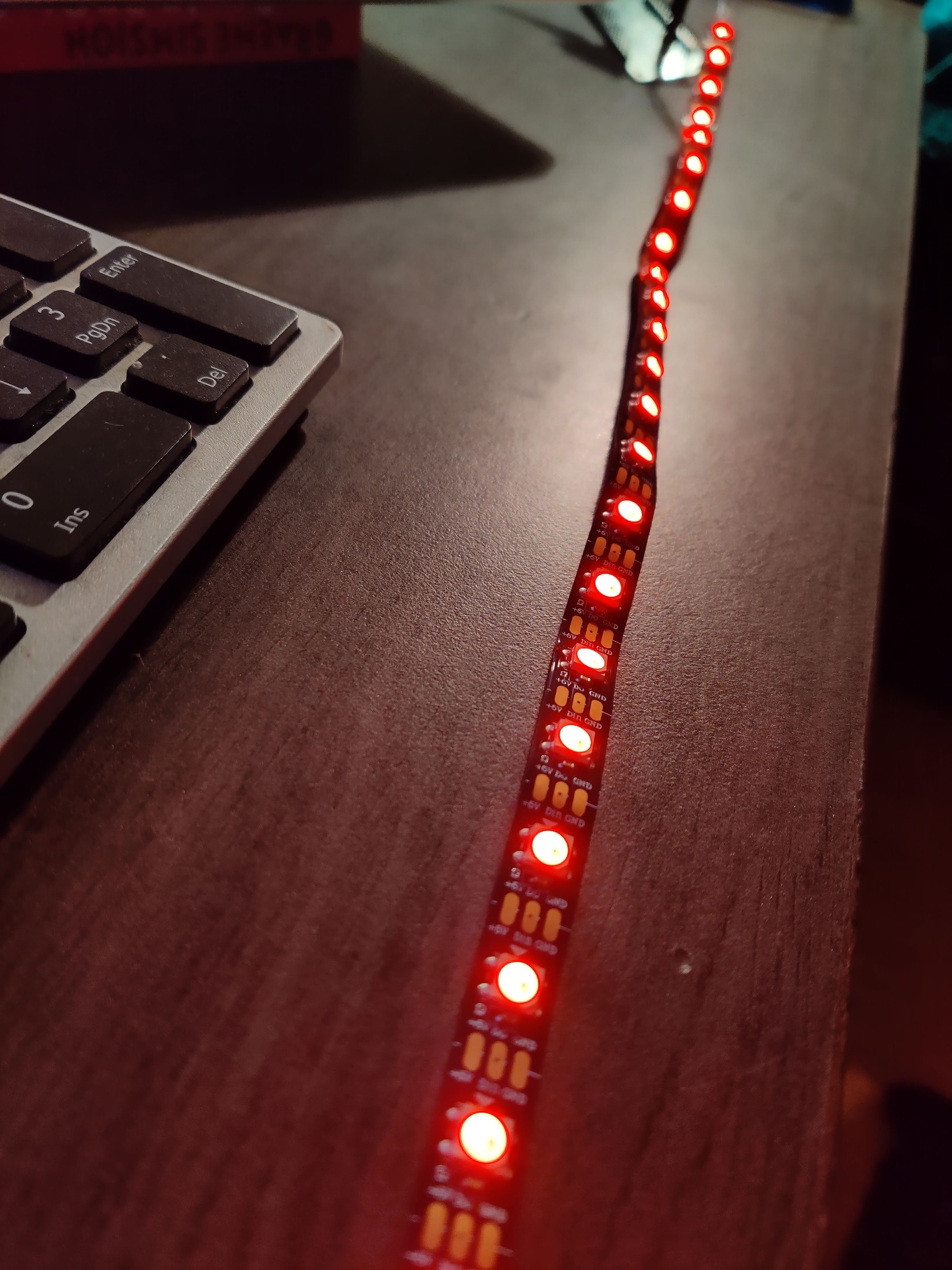
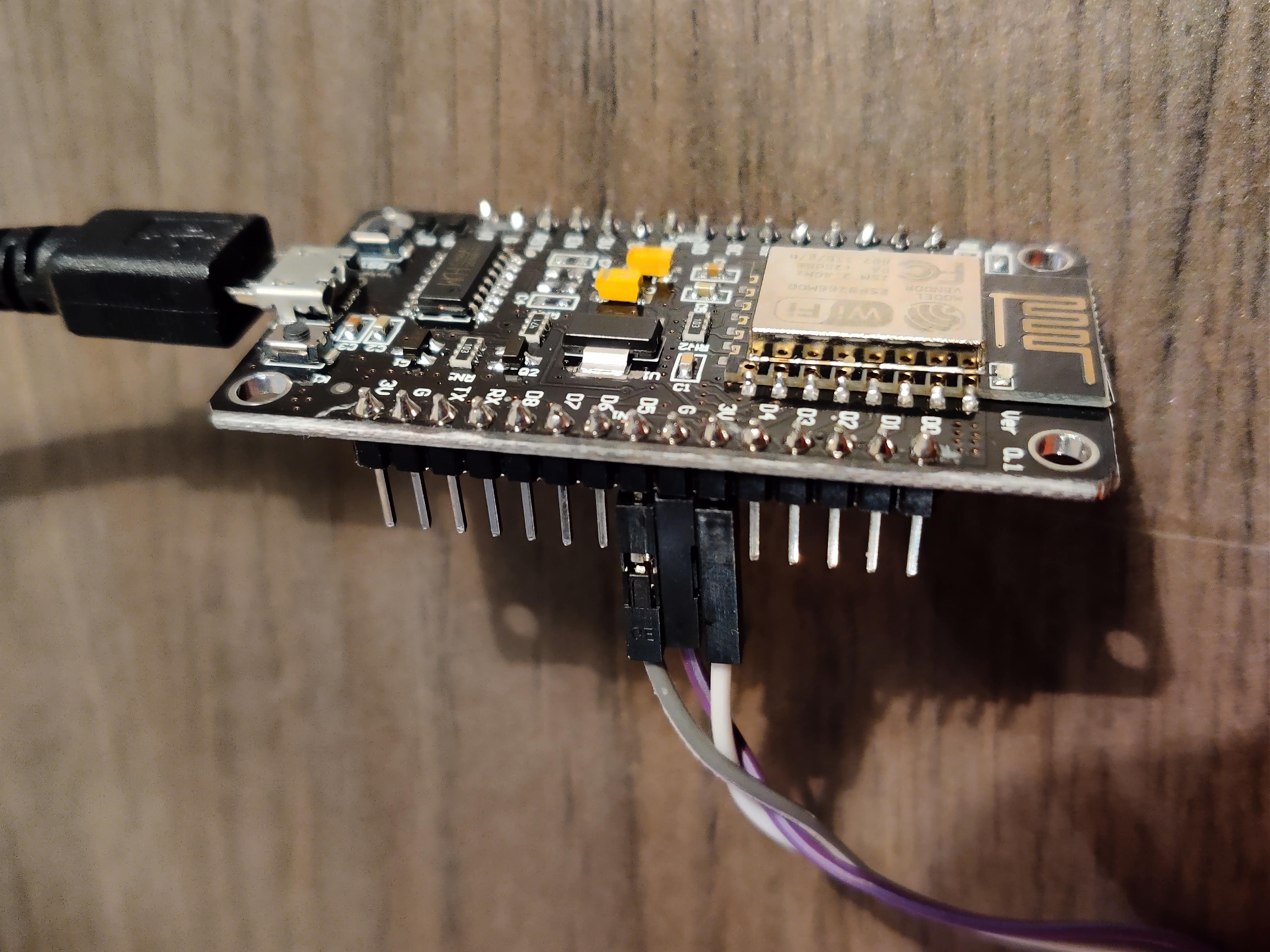
Now it's time to turn on our LED strip!
Connect your LED strip to the D5 PIN (if you can't find the D5 connect it to another PIN and change the LED_PIN in the code).
Define LED strip
The following code will add the NeoPixel library (learn more about this library here: https://learn.adafruit.com/adafruit-neopixel-uberguide/arduino-library-use) and make sure our Arduino knows where our LED strip is and how many lights it has. If your LED strip has different specifications, change it in the code.
Add the following code ABOVE the void setup():
// set up NeoPixel connection
#include <Adafruit_NeoPixel.h>
#ifdef __AVR__
#include
#endif
#define LED_PIN D5 // Where is the LED strip connected to?
#define LED_COUNT 30 // How many pixels does it have?
#define BRIGHTNESS 50 // NeoPixel brightness, 0 (min) to 255 (max)
Adafruit_NeoPixel strip(LED_COUNT, LED_PIN, NEO_GRB + NEO_KHZ800);
Start up LED strip
Now we'll start up our LED strip and set the brightness (brightness goes from 0 min to 255 max, but I recommend 50... 255 is REALLY bright).
Add the following code IN the void setup():
strip.begin();           // INITIALIZE NeoPixel strip object (REQUIRED)
strip.show();            // Turn OFF all pixels ASAP
strip.setBrightness(50); // Set BRIGHTNESS to about 1/5 (max = 255)
ledsOn(); // Calls the function to turn on each LED one by one
Turn the lights on
Maybe you've already noticed that we're calling a function that doesn't exist yet, that will be our next part of coding. If we want to turn on our lights we have to create a 'for loop' that turns on each individual LED one by one (don't know what a for loop is? Check it out here: www.arduino.cc/reference/en/language/structure/control-structure/for/).
Now we're going to be creating the function: ledsOn();
Add the following code BELOW void handleMessage():
void ledsOn() {
  for (int i = 0; i < strip.numPixels(); i++) { // For each pixel in strip...
    strip.setPixelColor(i, 0, 0, 255);         //  Set pixel's color to blue
    strip.show();                          //  Update strip to match
}
}
Upload!
Now is the fun part, let's upload our code to the NodeMCU... If everything works correctly your LED strip should now turn fully blue!
Are no pixels showing up?: have you connected the strip to the right PIN? Or maybe your internet connection is lost.
Are only some pixels not showing up?: check if you set the right amount of pixels!
Add Timing to the Timer
Now we're going to make sure that our timer actually... well... times, something.
There are different ways to do timing with Arduino, one is delay(), this stops the processing of our board for a defined period of time. We aren't going to be using this since our Arduino basically freezes during the delay, and we want our board to be updating regularly. So we are going to be using Millis(), this is a more elegant way of doing timing in Arduino, with Millis() we can still run code in between intervals.
If you're interested in how this works you can check out this article: https://www.arduino.cc/reference/en/language/functions/time/millis/
Let's add the code for Millis():
Put this code ABOVE the void setup()
unsigned long previousMillis = 0;        // will store last time the LED strip was updated
int interval = 1000;           // interval of our timer (milliseconds)
And let's put this code IN the void loop():
unsigned long currentMillis = millis();
// start TIMER RYTHM ******************************************************
  if (currentMillis - previousMillis >= interval) {
    previousMillis = currentMillis;

}
// end TIMER RYTHM ********************************************************
What we just did was create a rythm for our LED strip to turn off LEDs, in the next step we'll add the code to do just that.
Countdown!
In this step: we'll make a function that will make sure that each second (or whatever interval you've set) we turn off ONE LED at the end of the strip until all our LEDs are off.
We'll create an 'int' at the top called 'leds'. This will later tell our timer how many leds it still has to turn off.
Add the following code ABOVE the void setup():
int leds = LED_COUNT-1; // tels how many pixels should be lit
Now let's add the function 'timer();', this will be turning off a light every second
Add the following code BELOW the void ledsOn():
void timer() {  strip.setPixelColor(leds, 0, 0, 0);
if (leds > -1) {
    leds--;
} else {
blinkie();
}
}
We want to give some feedback to the user that the timer is done after all the lights have burned out. With 'blinkie();' the LEDs will blink red after the timer is done!
Add the following code ABOVE the void setup():
int blinkStatus = 1; // tells the blinkie(); function wether the light should be on or off
Add the following code BELOW the void timer():
void blinkie() {  if (blinkStatus == 1) {
    blinkStatus = 0;
    strip.clear();
  } else {
    blinkStatus = 1;
    for (int i = 0; i < strip.numPixels(); i++) { // For each pixel in strip...
      strip.setPixelColor(i, 255, 0, 0);         //  Set pixel's color (in RAM)
      strip.show();                          //  Update strip to match    }
 }
}
}
Finally we have to call the function in our void loop();,
Remember the TIMER RYTHM we added in step 8? In this if statement we'll call the function timer();.
TIMER RYTHM should now look like this:
// start TIMER RYTHM ******************************************************
  if (currentMillis - previousMillis >= interval) {
    previousMillis = currentMillis;
    timer();
strip.show();}
// end TIMER RYTHM ********************************************************
Now upload this code!
Right now your LED strip should be turning off 1 LED each second and blink red when it's done...
Now let's make this motherlover remote controlled!
Make It Remote Controlled: Part I
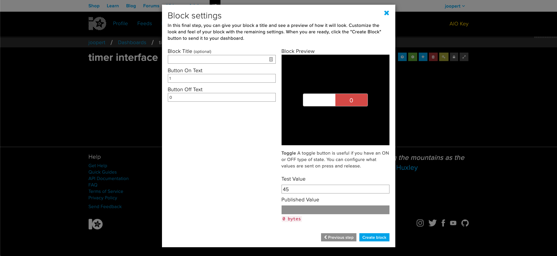

We've got our timer, that's all fine and dandy but I promised you that you would be able to control it with your phone right? Let's enter the final stage of our project: making our timer remote controlled.
Still got your Adafruit tab open? Let's travel to back to io.adafruit.com and let's go to our timer interface dashboard and create a new block: TOGGLE
- Connect the toggle to the TIMER feed
- Set the ON value to: 1
- Set the OFF value to: 0
The reason for this is that Adafruit doesn't send text data to our NodeMCU, but only numbers.
You can also give the Toggle a name if you like, maybe: 'On/Off switch'
Now let's head back to the Arduino IDE
Just to make sure our code is up to date, let's UPLOAD our code once again.
OPEN THE SERIAL MONITOR once it's done uploading and PRESS THE TOGGLE on our Adafruit dashboard a few times. We should now be seeing something like this popping up in our serial monitor:
received <-  0
received <-  1
received <-  0
received <-  1
received <-  0
This means that we can actually send controls to our NodeMCU!
If you aren't receiving these messages, check if your Adafruit Data in your config.h is still correct.
Make It Remote Controlled: Part II
Now all there's left is doing something with our received controls.
To do that we got to alter our TIMER RYTHM if statement in the void loop(); a little bit.
We're gonna tell our NodeMCU that it should only start the timer once we've received '1' (which means: ON) from Adafruit.
First let's collect the data Adafruit sends us
Add the following code ABOVE the void setup():
int adaData; // collects the data AdaFruit sends us
Now let's actually collect that data
Add the following code INSIDE the void handleMessage():
adaData = data->toInt();
Let's change our void loop();
TIMER RYTHM should now look like this:
// start TIMER RYTHM ******************************************************
if (currentMillis - previousMillis >= interval) {
    previousMillis = currentMillis;

  if (adaData == 0) {
      Serial.println("im not running");
    } else if (adaData == 1) {
      timer();
    }
    strip.show();
}

// end TIMER RYTHM ********************************************************
UPLOAD your code...
Now you should be able to turn the timer on and off by using the switch in Adafruit!
Play Around! We're Done... or Are We?
Right now you should have a fully functioning remote timer! If that's it for you then thank you for coming along with this project!
If you want to continue a bit longer, in the next few steps we're gonna be adding a RESET button for our timer!
EXTRA: Create Momentary Button
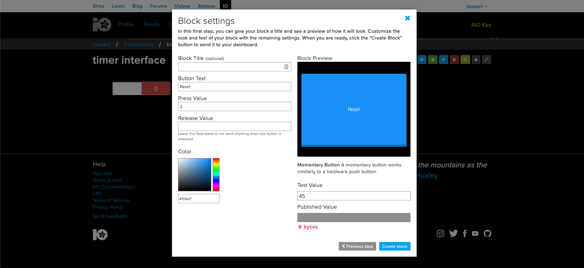
Let's return to our dashboard. Now we want to CREATE A NEW BLOCK again.
- Create a Momentary button
- Connect it to the 'timer' feed
- Set the press value to: 2
- REMOVE the release value
- Give it a nice color!
Conveniently the momentary button is already called 'Reset'!
Once you've created this block test it out, the button works if you receive:
received <- 2
In your serial monitor.
If you aren't seeing this message, try re-uploading the sketch
EXTRA: Add the Reset Function
To make the reset button do anything we need to add a function that resets all the LEDs back to the original state.
Add the following code BELOW the void blinkie():
void rerun() {
  leds = LED_COUNT;
  ledsOn();
}
Now all there's left is calling our function, for that we have to change TIMER RYTHM one last time
TIMER RYTHM should now look like this:
// start TIMER RYTHM ******************************************************
if (currentMillis - previousMillis >= interval) {
    previousMillis = currentMillis
    if (adaData == 0) {
      Serial.println("im not running");
  } else if (adaData == 1) {
      timer();
  } else if (adaData == 2) {
      rerun();
    }
    strip.show();
}

// end TIMER RYTHM ********************************************************
UPLOAD your code...
Now you should also be able to reset the timer by pressing the button!