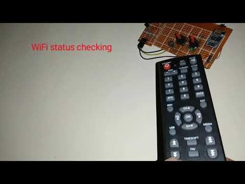
Remote Controlled Light With WiFi Status Checker
by Jeshanthan in Circuits > Remote Control
720 Views, 5 Favorites, 0 Comments
Remote Controlled Light With WiFi Status Checker
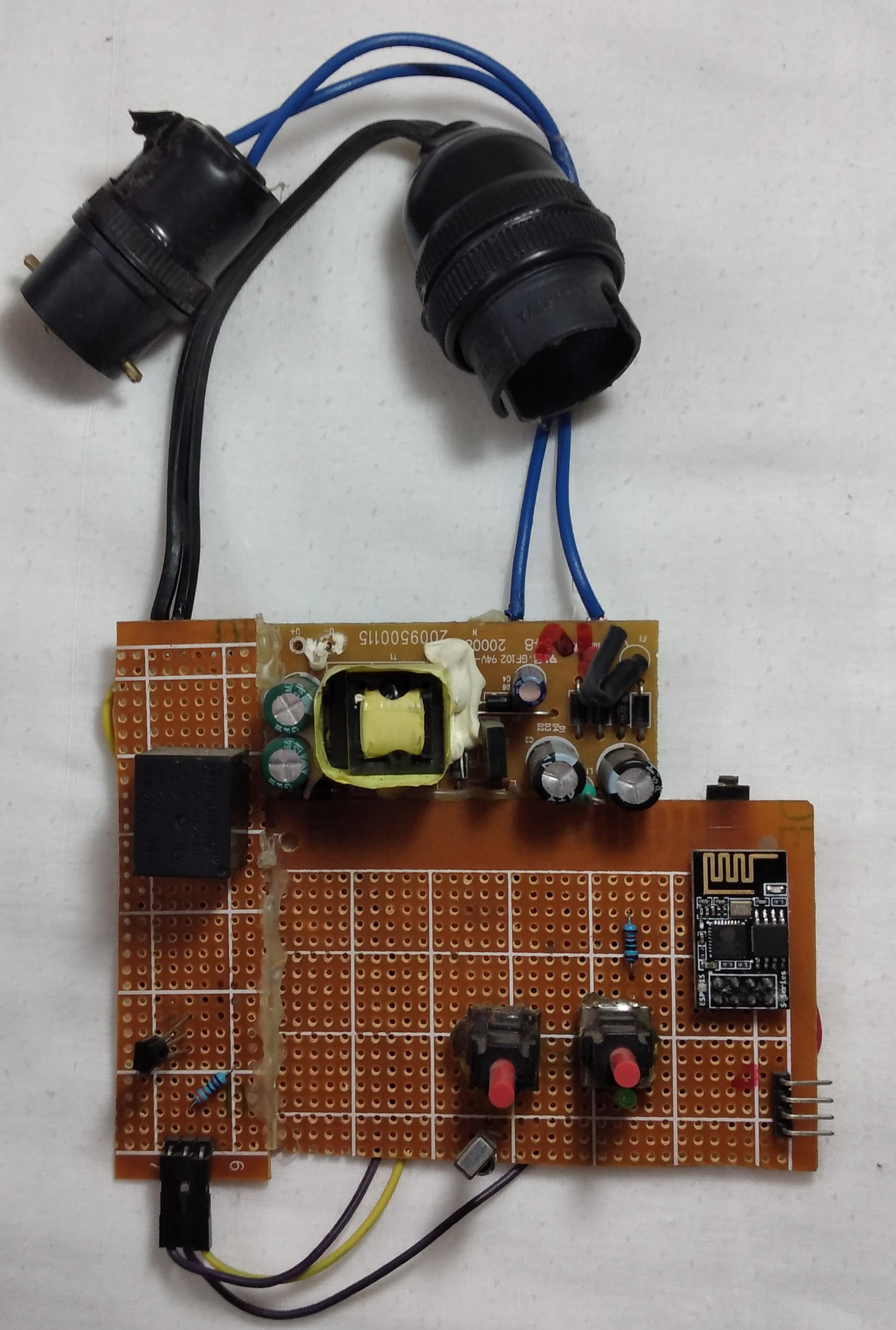
This instructable is about a remote controlled light, which I made. I've added another feature which is WiFi status checking. I've done this because whenever I sleep on bed I faced two different kinds of problem. The first one is turning off the light bulb after I slept which is a hassle because I always have to get-off the bed in order to turn it off. The second one is I usually like to watch YouTube before I sleep and while I am watching YouTube the WiFi or the phone stops randomly at any time. At this moment I always have to go to the server room in order to check the WiFi connection. In this instructable I solved those two kinds of problem and you can build it by following this instructable.
Supplies
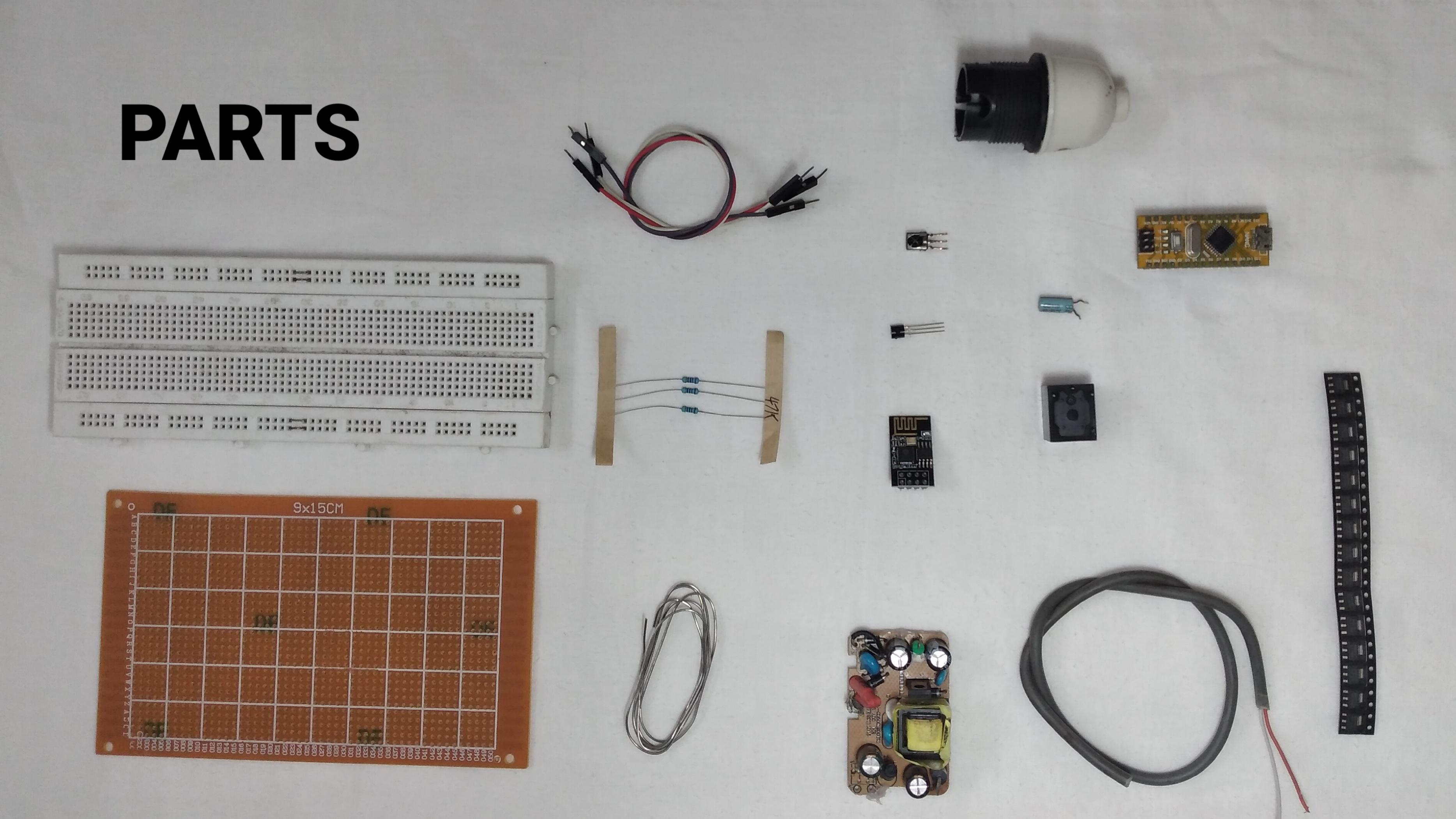
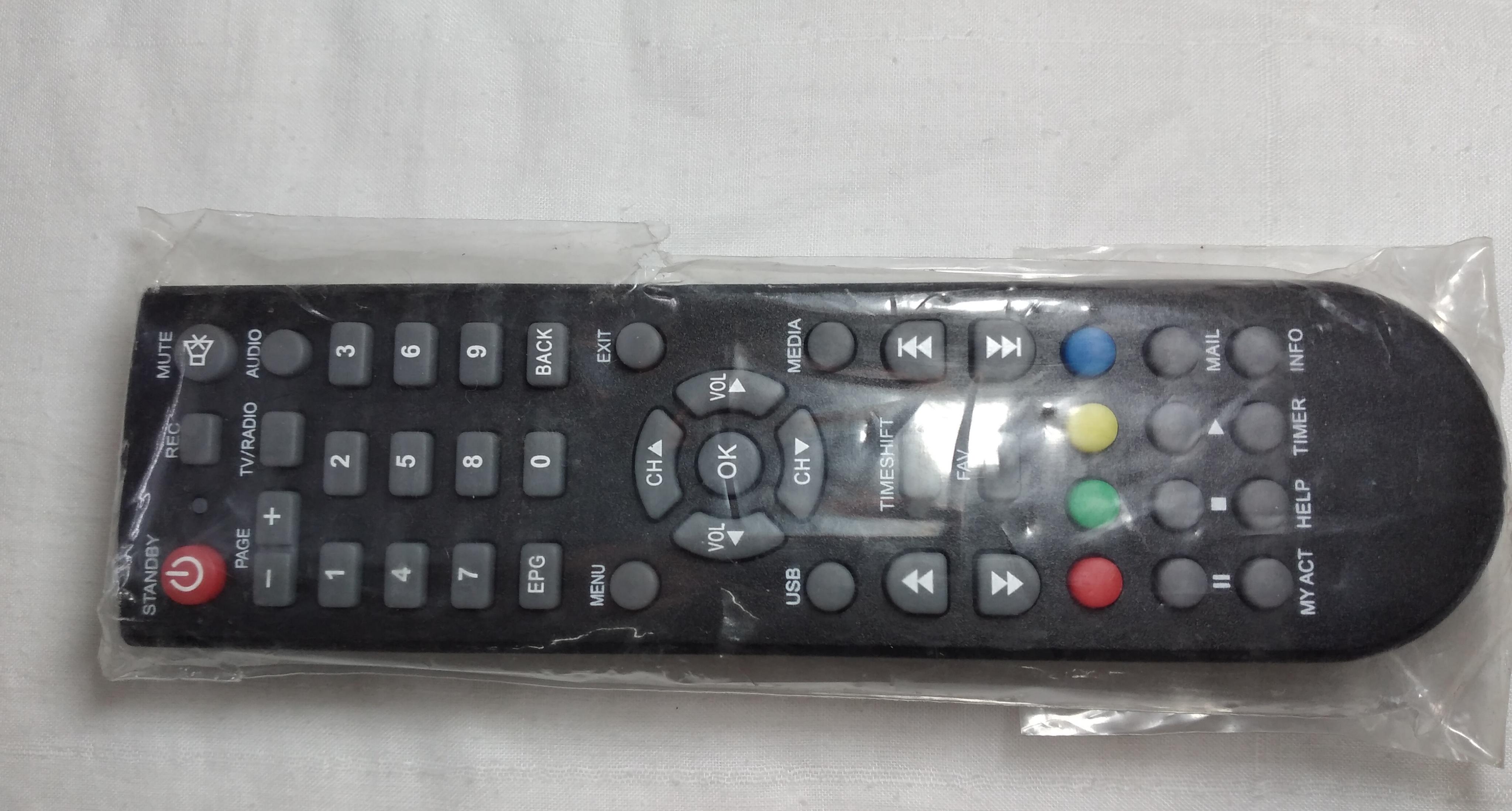
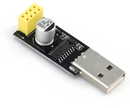

PARTS YOU NEED:
- 9x15cm perfboard - 1pcs purchase it right away from here
- breadboard - 1pcs purchase it right away from here
- male-to-male jumper wire - 3pcs purchase it right away from here
- silver coppered wire - 70cm purchase it right away from here
- Thick elctrical wire - 4pcs purchase it right away from here
- Holder for light bulb ( according to your country) - 1pcs purchase it right away from here
- 47k resistor - 1pcs purchase it right away from here
- relay 5v - 1pcs purchase it right away from here
- 1uf capacitor 16v - 1pcs purchase it right away from here
- arduino nano - 1pcs purchase it right away from here
- BC557 pnp transistor - 1pcs purchase it right away from here
- 230 v to 5v SMPS - 1pcs purchase it right away from here
- ESP-01s - 1pcs purchase it right away from here
- IR sensor(vs1838b) - 1pcs purchase it right away from here
- AMS1117-3.3 - 1pcs purchase it right away from here
- diode 1N4007 - 1pcs purchase it right away from here
- Any kind of Ir remote ( should have at least 2 buttons) - 1pcs purchase it right away from here
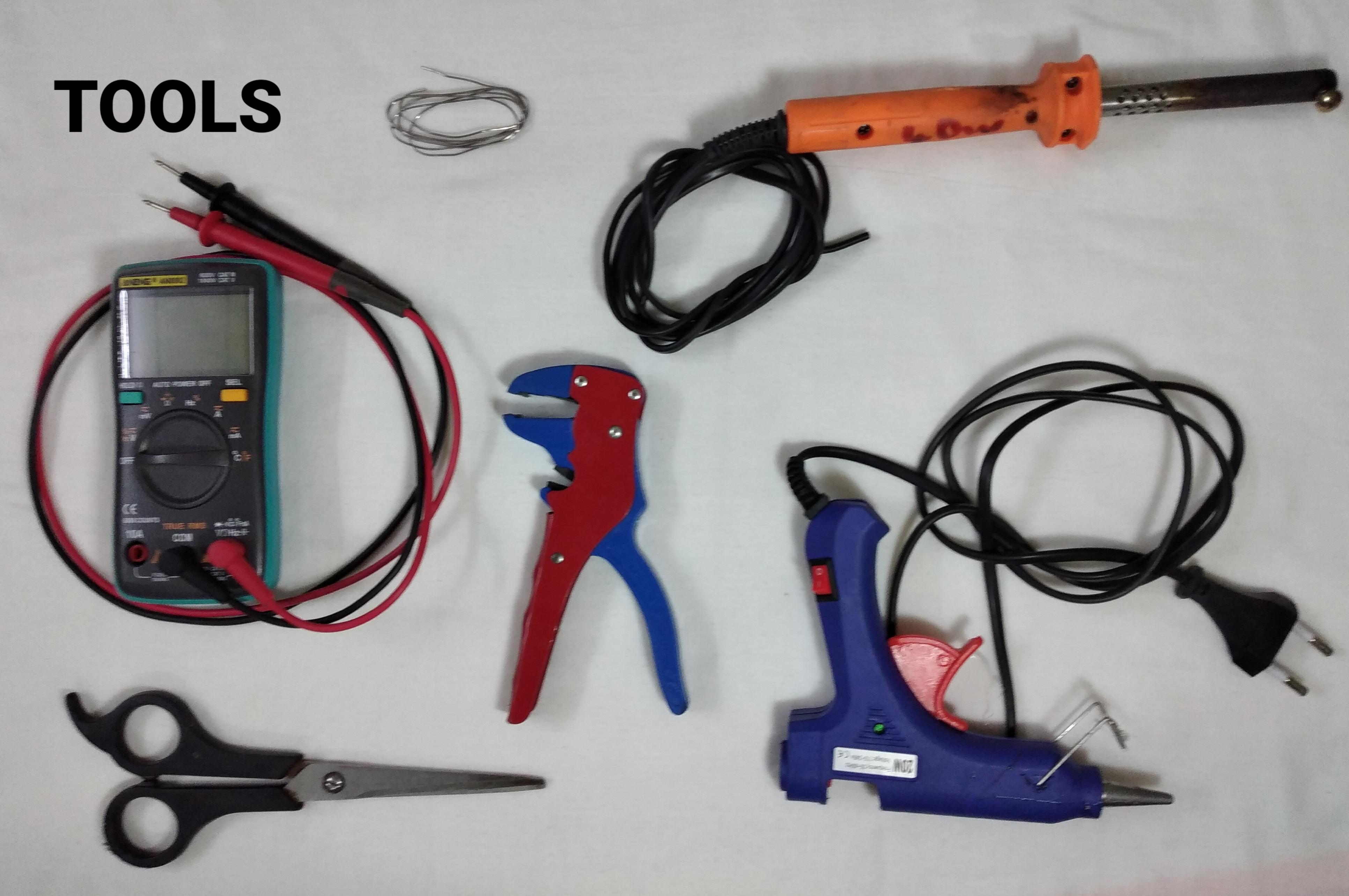
TOOLS YOU NEED:
- Multimeter purchase it right away from here
- Laptop purchase it right away from here
- ESP-01s programmer purchase it right away from here
- Wire stripper purchase it right away from here
- Hot glue gun purchase it right away from here
- Scissors purchase it right away from here
- Solder wire purchase it right away from here
- Soldering iron purchase it right away from here
- USB type-B cable purchase it right away from here
NECESSITIES:
- You should have WiFi connection in your house
Software Configuration
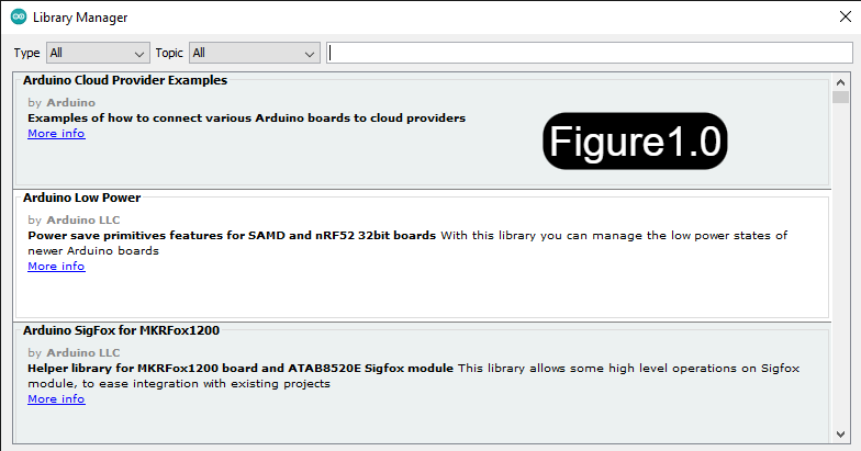
First you should have download and install Arduino.
Download link :- "https://www.arduino.cc/en/software".
After installing Arduino ,go to tools and click library manager. It will open a new dialogue box which looks like Figure1.0.
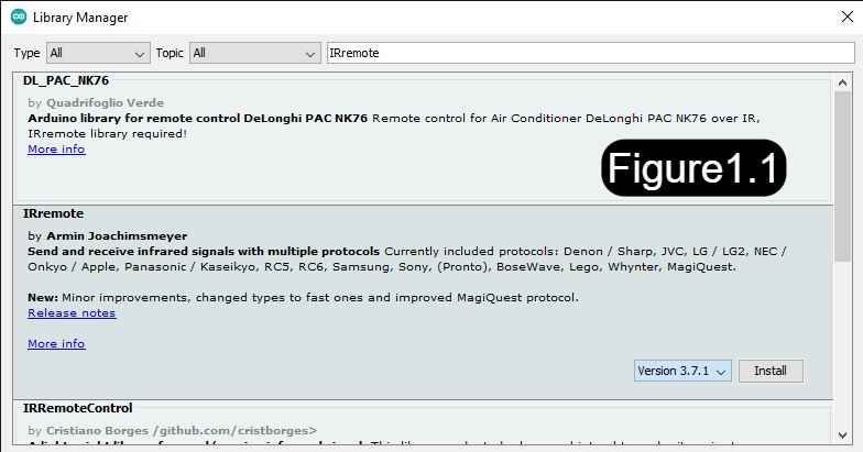
In the search bar type "IRremote" and you'll see this(Figure1.1).
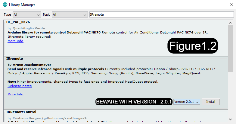
You will see the library "IRremote" and set the version to 2.0.1 (because newer versions are little bit hard to interact with) and click install(Figure1.2).
Then close the dialogue box.
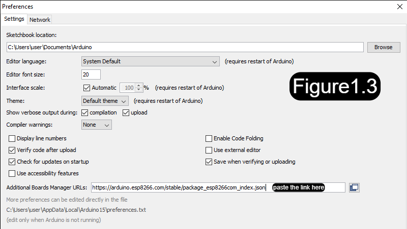
After that go to file and click preferences. Here you can see an empty box named "Additional Boards Manager URLs". paste the link "https://arduino.esp8266.com/stable/package_esp8266com_index.json" in that box and click ok.(Figure1.3)
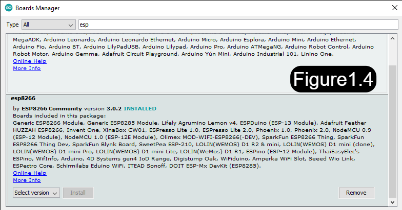
Then go to Tools and click Boards Manager and in the search bar type ESP (Figure1.4). You can see the board esp8266. Install it by clicking install button.
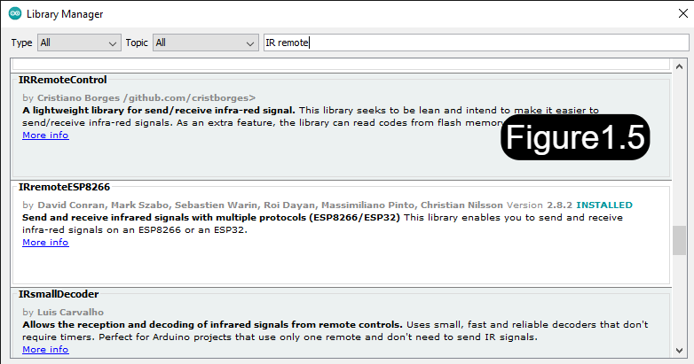
We've already installed a library called "IRremote". Now we have to download another library called "IRremoteESP8266". Go to library manager and search this "IRremoteESP8266" and install here you don't have to worry about the version.(Figure1.5)
WHOO! WE HAVE SUCCESSFULLY FINISHED THE SOFTWARE CONFIGURATION
Gathering the IR Codes

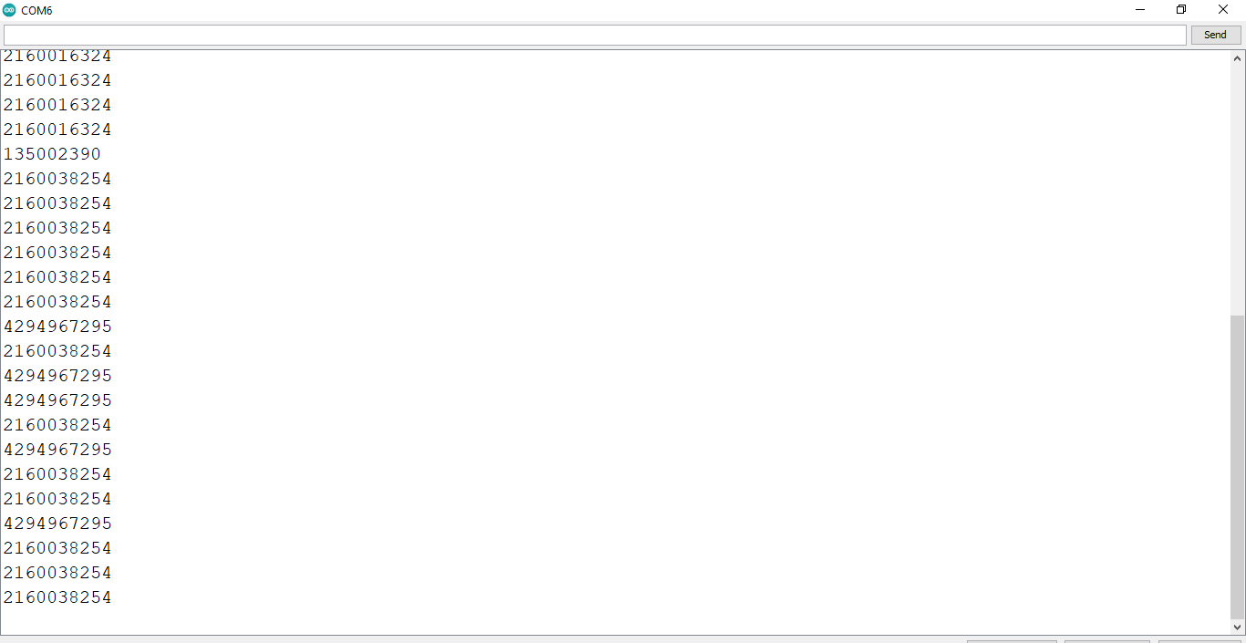

Get the bread board , Arduino NANO , IR receiver, jumper wire and connect the first pin of IR receiver to pin 11. The second one goes to gnd. Third one goes to 5v and upload the code ir_code_checker.ino. (which is provided below). Open up the serial monitor set the baud rate to 9600 and press the button on the remote get your codes. You have to get two codes from two different butons. One to turn the light on/off and another one to check the status of the WiFi.
See the images for further details
Downloads
Programming the Esp-01s
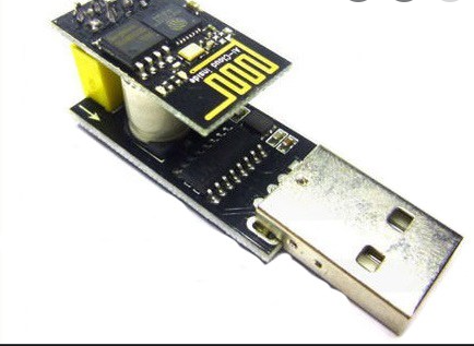
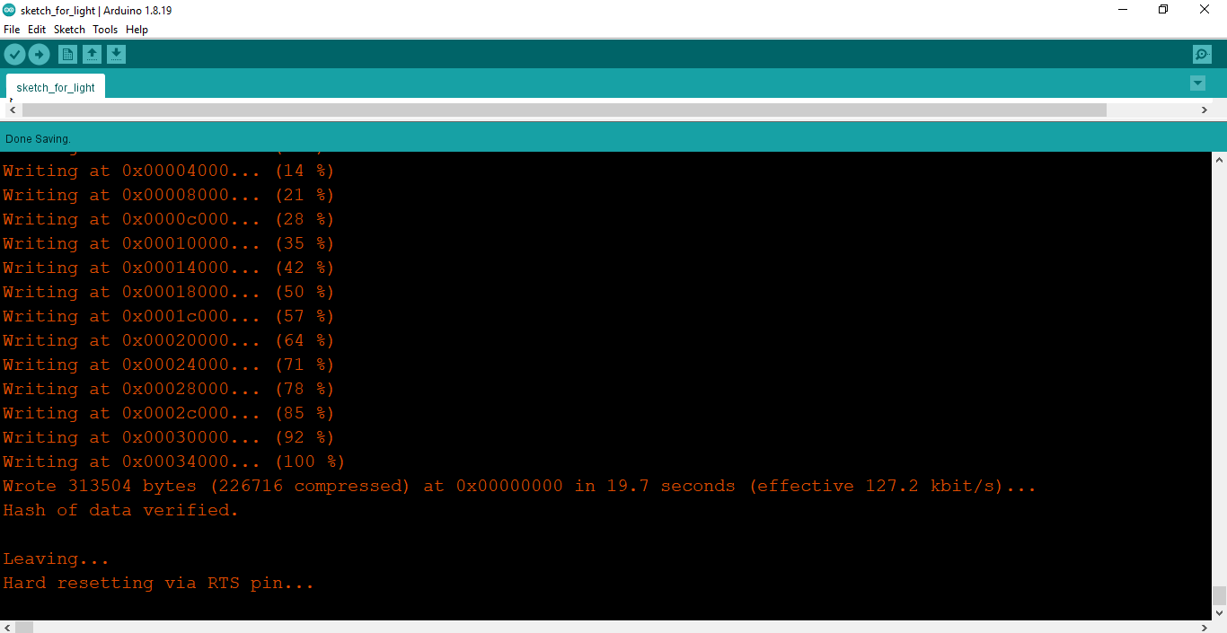
Connect your Esp-01s to your ESP programmer and select the board to Generic ESP8266 module and upload the code given below
CONSIDER THIS BEFORE UPLOADING
- Fill your WiFi name in your_SSID string
- Fill your WiFi password in your_PASSWORD string
- Fill the on/off ir code right before the comment //Type your on/off code
- Fill the WiFi status checking IR code right befor the comment //Type your WiFi status checking code
Explanation of the code are provided next to each line in the code
Downloads
Build the Circuit
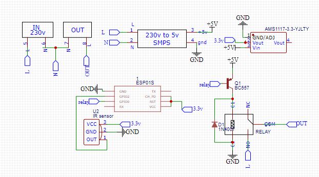 - A Simple and Powerful Electronic Circuit Design Tool - Google Chrome 07_07_2022 21_50_23.png)
The schematic of the circuit is presented above
NOTE
I didn't add the 47k resistor between transistor base and gpio 0 because it has a resistor inbuilt in esp-01s because I designed the esp-01s myself but the commercial ones don't have that so if you are using a commercial one, you should put that resistor
Soldering
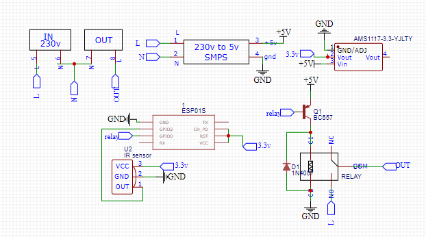 - A Simple and Powerful Electronic Circuit Design Tool - Google Chrome 07_07_2022 21_50_23.png)
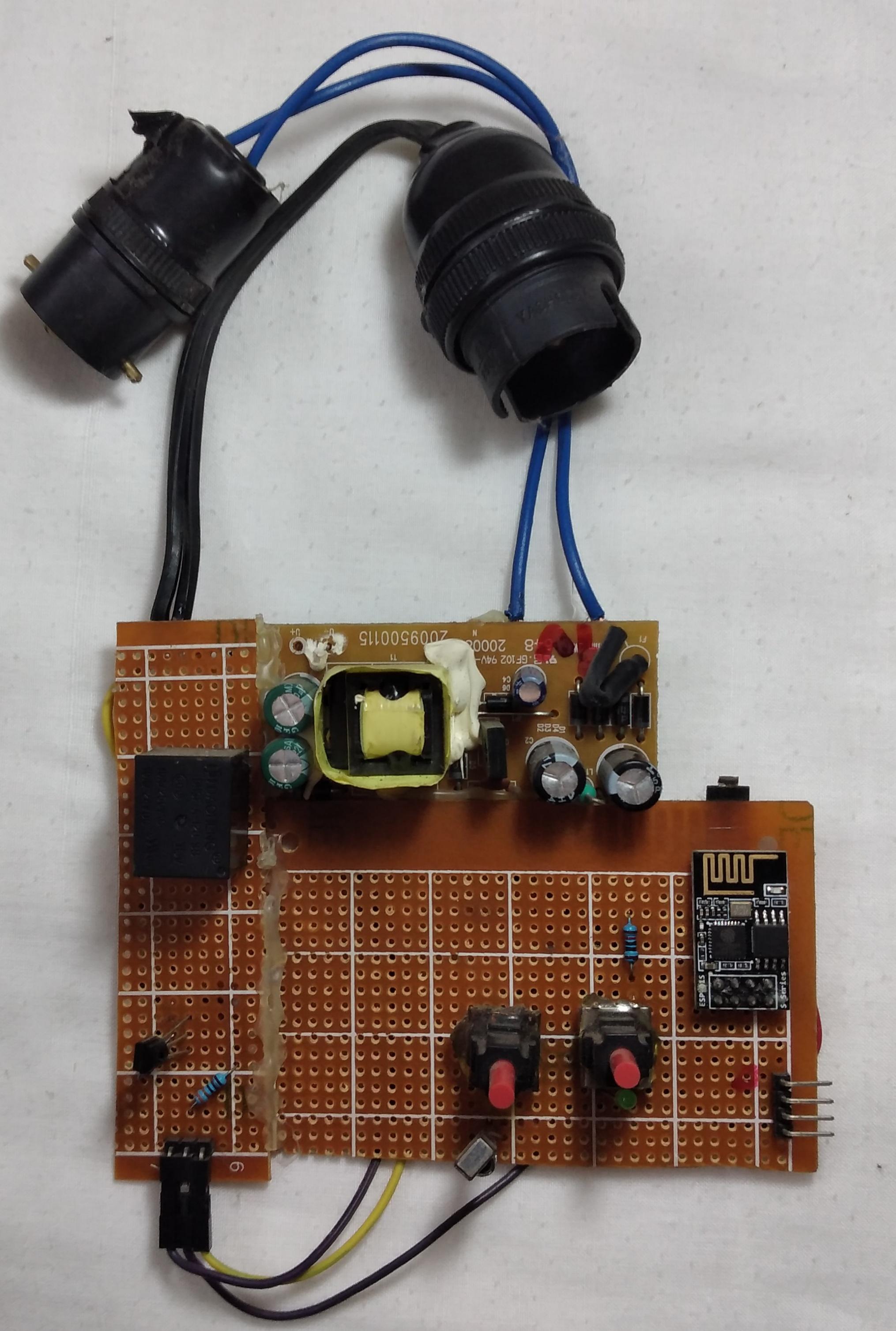
Solder all the components according to the schematic
Protection and Mounting
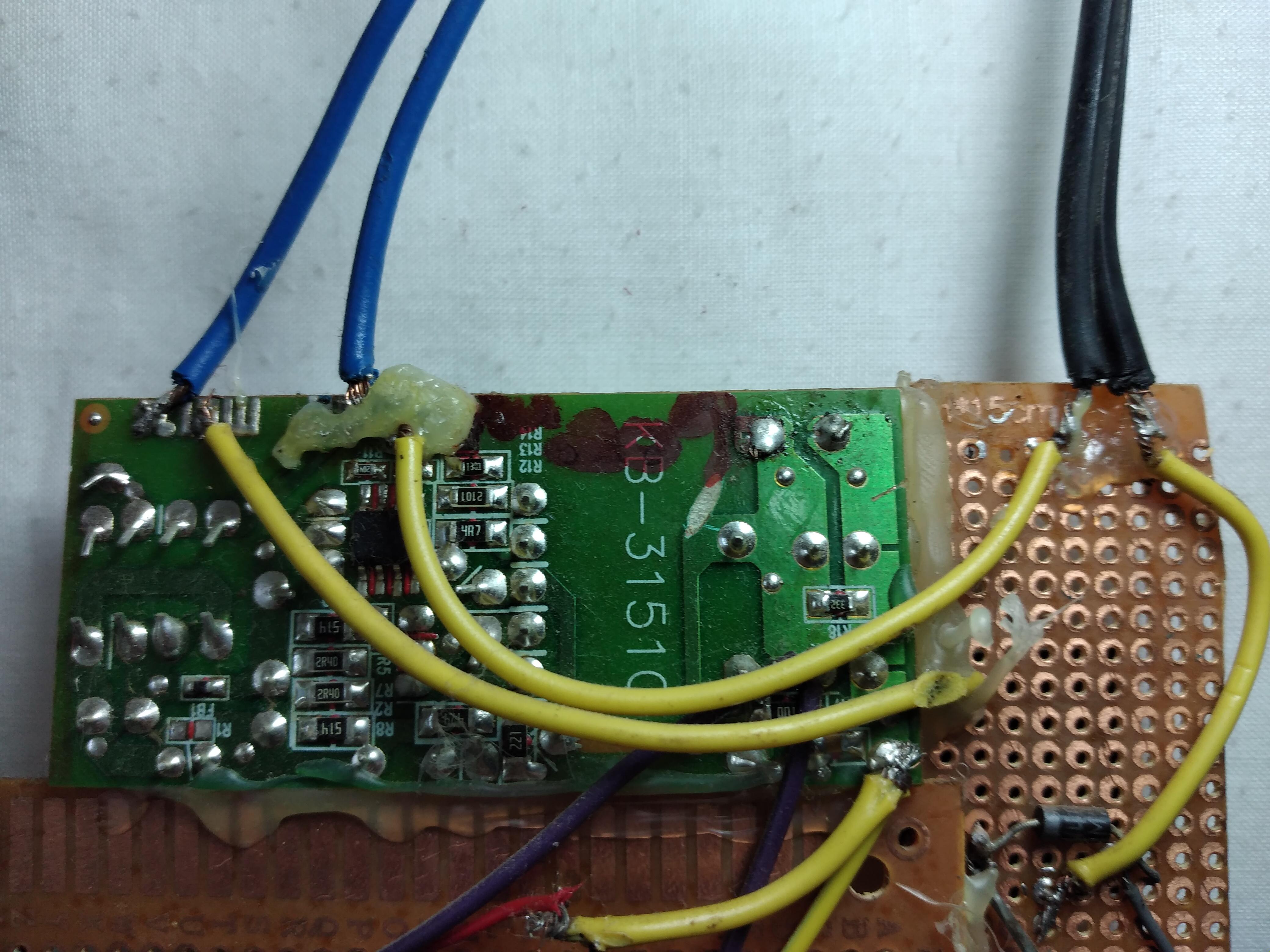
Protect the high voltage parts with hot glue and mount it on the wall with the help of hot glue.
WHOLA WE'VE SUCCESSFULLY MADE THE CIRCUIT
Why Am I Using a PNP Transistor
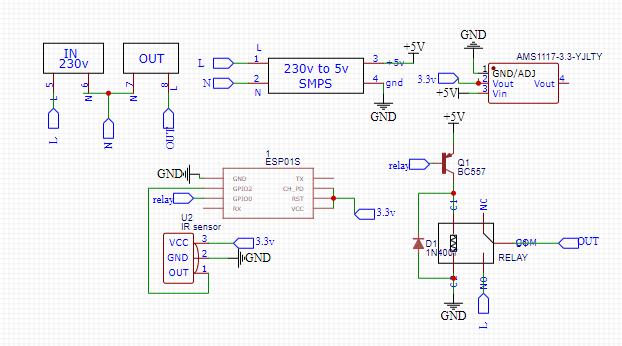 - A Simple and Powerful Electronic Circuit Design Tool - Google Chrome 07_07_2022 21_50_23.png)
Because whenever gpio0 pulled down to ground it will go to the programming mode. An NPN transistor allows current to flow from base to emitter and emitter should be connected to ground while using an NPN transistor so the gpio0 will get pulled down to 0v so it will go to programming mode. In order to omit this I used a PNP transistor.
What Is the Use of the Diode Here
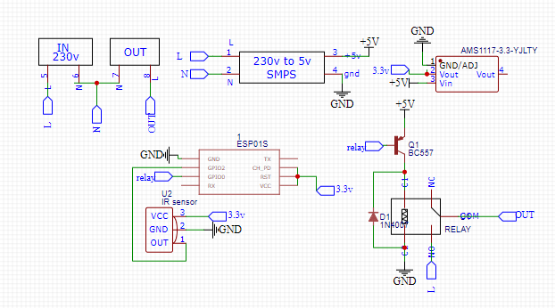 - A Simple and Powerful Electronic Circuit Design Tool - Google Chrome 07_07_2022 21_50_23.png)
The diode D1 is here to protect the PNP transistor. Coils have a common behavior which is producing a big voltage spike when we disconnect a dc power source (which is connected beforehand) this would happen in opposite polarity. So the diode is connected across the coil terminals in order suppress that big voltage spike because of this our transistor would be happy.
How the Circuit Works
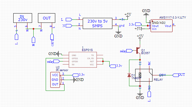 - A Simple and Powerful Electronic Circuit Design Tool - Google Chrome 07_07_2022 21_50_23.png)
Firstly, when we input 230v in the input the SMPS will step it down to 5v. Then the ams1117-3.3 regulator will step that down to 3.3v because the ESP needs 3.3v to work. The 5v supply is needed to power the relay. Then the esp-01s will execute our code and it will do nothing until we press any of those 2 buttons that we've programmed earlier. If we press the on/off button, it will turn the light on. If we press the WiFi status checking button, it will switch the state of the light depending on the connectivity to the WiFi.
Test Run
