Remote Controlled Car (With IR Receiver)
by Rushil_R in Circuits > Arduino
736 Views, 0 Favorites, 0 Comments
Remote Controlled Car (With IR Receiver)

This is a remote control car that can be programmed to use any remote with an infrared single. It uses an infrared receiver (IR) to catch the signal and decode it into commands that you can program. Moreover, It is simple and requires minimal wiring skills. It's fast, effective and long-range (1-5 meters, 3-15 feet). Additionally, it's good for all ages and is compatible with many other IR projects such as a garage door opener. It can be programmed to move in your 4 directions forward, back, left, right, and stop. It's a beginner-friendly project for anyone to take up.
Supplies

Electronics
- 1xIR receiver
- 2xLEDs
- 1xH-Bridge l293D
- 1xArduino
- 1xBreadboard
- 1xRemote (TV remote can work if uses infrared signal)
Tools
- 1xWire cutters
- 1xScrewdriver
Car Components
- 1x360 wheel
- 1xCar chassis of some kind (wood, 3d printed or plastic)
- 2xMicro 360 Degree Continuous Rotation Servo
- 2xWheel for FS90R
Power/Connections
Research

Tasks that helped with the creation of this car included making the following
- 2-bit full adder
- Lots of wiring
- Making a potentiometer-controlled motor with wheel and pushbuttons
- Coding IRs and remotes
- Basic understanding of codes and functions
- Working on a breadboard
- Using wire cutters
- Using an Arduino
- Coding RGBs
Having a basic understanding of C++ and working on a breadboard is all you really need to know for the car. If you have used the components before that will help you as well but I explain everything thoroughly so even if you don't know how to code or use a breadboard or any of the parts I will explain in detail later on.
Car Assembly


- The wheel assembly is quite easy, you should notice the wires are already connected to the servo. All you need to do is put on the wheel and screw it in.
- From here get your car chassis and screw/tape/glue your wheels to the back of the car (this car will be rear-wheel drive).
- Then, just like how you see in the image, secure the 360 wheel 3/4ths of the way up the car in the middle.
- Once that is done it is time to grab your breadboard and Arduino. Secure your Arduino to the top of your car chassis and in front of the Arduino place your small breadboard.
- Make sure to leave room for 2 9V batteries on your chassis either underneath, on top, or to the sides as they need to be securely taped on in a later stage.
Wiring Electronics
.png)


Wiring Instructions
If you are unfamiliar with how breadboards work there are 2 things to remember:
- Horizontal holes are linked together and not across the divider
- Vertical bus strips continue down the side of the breadboard only and don't cross the middle divider
*There are images I have linked if you click on more images to visually see what I am talking about*
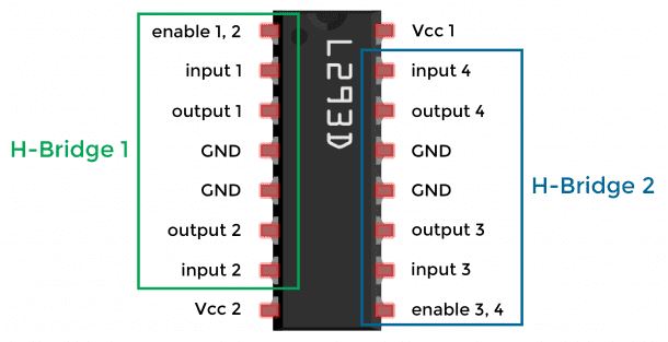
H-Bridge L293D
Firstly, the chip with 16 pins (this will act as the brains for the wheels) will have to be placed in the middle of the breadboard across the divider running parallel to the divider. When placing the chip look for the text and dot/indent to be able to tell where the chip's first connection is (if you want to follow my design exactly place it so that the text is orientated for you to read and the indent is on the closer side to the Arduino).
Second, once you have properly placed your H-Bridge it's time to start wiring, this is where you will need your wire cutters (use the ones that came in spools, not the male-male jumper wires). Get your red wires and make connections to the four most outer pins; this will later provide power to the chip and enable pins 1,2,3 and 4 of the H-Bridge. Next, the two middle pins on both sides need to be wired to ground. Finally, you need to connect the power and ground wire from your servo motors to the pins next to the ground pins of the chip. During that connection, the 2 wires need to be on the same side of the chip so they are not crossing (with the specific motors I linked you may need to remove the cap and RC single wire which is the orange one because all you need are the power and ground wires which are Red and Brown for that servo - link to a video on how to do this)
Finally, you should notice there are 4 pins left, with those pins use m-m jumper wires to connect your remaining H-Bridge pins to the Arduino (I recommend doing that in one colour).
- Connect input 1 to pin 6
- Connect input 2 to pin 7
- Connect input 3 to pin 5
- Connect input 4 to pin 4
*Link to a diagram of the H-Bridge*
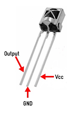
Infrared Receiver (IR)
This is an easier component to wire but is one of the most important parts of the build. The IR has 3 pins, power, ground and output. With the receiver facing you place it on the breadboard. The ground is the middle pin, power is the right pin and output is the left pin (image link). Connect power and ground the same way you did with the chip, take your output pin to the Arduino using a male-male jumper wire and connect it to pin 11.
LEDs
Your LEDs are meant to represent headlights so place them near the front of the car. The longer leg of the LED is power and the shorter leg is ground. Connect the ground to the breadboard and take the power pin to the Arduino using your jumper wires.
- Connect your left LED to pin 12
- Connect your right LED to 13
Battery Connections
Now using your batteries put the two different caps onto the two 9V batteries. One battery will supply power to the Arduino and for the other take out any one of the power sources (red wires) going to the H-bridge and connect the power side of the battery to that pin. Then ground the other wire.
Tips/Troubleshooting
- Tip: Color coding your wires makes troubleshooting very easy; conventionally red wires are used to represent power, black wires are used to represent ground and other connections between components are up to your discretion.
- Tip: When looking at your connections on a breadboard make sure to line up your connections with the components.
Far too often, the main problem with components not working is 1 of 5 things:
- Your power and ground are not connected properly or are swapped
- Your wires are off by one pin on the breadboard
- The pin you have connected to your Arduino is not the same one you declared in your code
- Your wires are not deep enough in the breadboard and aren't sending the signal properly
- Your breadboard may be bent and the aluminum under is not being reached by all the pins of your chip
Coding

To upload the code just copy and paste it into the Arduino editor and connect your computer to your Arduino. To program your remote controller with your IR just open up the serial monitor then click the button you want to be assigned to that command e.g. if your want 1 to be forward click 1 on your remote while pointing it at the IR then look for the Hexacode that pops up and copy that into "if (results.value == 0x000000)" keep the 0x but replace the other long string of numbers and letters with your Hexacode. Once that is done you should have a fully working remote-controlled car, congratulations!
Side note, if your wheels aren't spinning in the direction you want try flipping your servo motor connection.
#include <IRremote.hpp>

#include <IRremote.h>

int RECV_PIN = 11;
IRrecv irrecv(RECV_PIN);
decode_results results;

int motor_pin1 = 4;    // Left motor
int motor_pin2 = 5;
int motor_pin3 = 6;    // Right motor
int motor_pin4 = 7;
int led1 = 12; // Left Led
int led2 = 13; // Right Led

void setup ()
{
  irrecv.enableIRIn();
  pinMode(motor_pin1,OUTPUT);    // Left motor
  pinMode(motor_pin2,OUTPUT);
  pinMode(motor_pin3,OUTPUT);    // Right motor
  pinMode(motor_pin4,OUTPUT);
  pinMode(led1,OUTPUT);
  pinMode(led2,OUTPUT);
  Serial.begin(9600);
}

void loop() {

  //if some date is sent, reads it and saves in state
  if (irrecv.decode(&results)) {
    Serial.println(results.value,HEX);
    irrecv.resume();   // Receive the next value
    }

  if (results.value == 0xC1AA4DB2) {   // up this is where you put in your IR remote button #
    digitalWrite(motor_pin1,LOW);      // Left motor backward
    digitalWrite(motor_pin2,HIGH);
    digitalWrite(motor_pin3,LOW);      // Right motor backward
    digitalWrite(motor_pin4,HIGH);
    digitalWrite(led1,HIGH);
    digitalWrite(led2,HIGH);
      Serial.println("Go Backward!");
    }

  //if some date is sent, reads it and saves in state
  if (irrecv.decode(&results)) {
    irrecv.resume();   // Receive the next value
    }

    if (results.value == 0xC1AA0DF2) {  // down  this is where you put in your IR remote button #
      digitalWrite(motor_pin1,HIGH);      // Left motor forward
      digitalWrite(motor_pin2,LOW);
      digitalWrite(motor_pin3,HIGH);      // Right motor forward
      digitalWrite(motor_pin4,LOW);
      digitalWrite(led1,LOW);
      digitalWrite(led2,LOW);
        Serial.println("Go Forward!");
    }


  //if some date is sent, reads it and saves in state
  if (irrecv.decode(&results))
  {
    irrecv.resume();   // Receive the next value
  }

    if (results.value == 0xC1AA8D72) { // |<< left  this is where you put in your IR remote button #
      digitalWrite(motor_pin1,HIGH);      // Left motor backward
      digitalWrite(motor_pin2,LOW);
      digitalWrite(motor_pin3,LOW);       // Right motor forward
      digitalWrite(motor_pin4,HIGH);
      digitalWrite(led1,LOW);
      digitalWrite(led2,HIGH);
        Serial.println("Turn Left!");
    }

  //if some date is sent, reads it and saves in state
  if (irrecv.decode(&results)) {
    irrecv.resume();   // Receive the next value
    }

    if (results.value == 0xC1AACD32) { // >>| right this is where you put in your IR remote button #
      digitalWrite(motor_pin1,LOW);       // Left motor forward
      digitalWrite(motor_pin2,HIGH);
      digitalWrite(motor_pin3,HIGH);      // Right motor backward
      digitalWrite(motor_pin4,LOW);
      digitalWrite(led1,HIGH);
      digitalWrite(led2,LOW);
        Serial.println("turn Right!");
    }

  //if some date is sent, reads it and saves in state
  if (irrecv.decode(&results)) {
    irrecv.resume();   // Receive the next value
    }

    if (results.value == 0xC1AAA15E) { // PLAY/PAUSE  this is where you put in your IR remote button #
      digitalWrite(motor_pin1,LOW);       // Stops left motor
      digitalWrite(motor_pin2,LOW);
      digitalWrite(motor_pin3,LOW);       // Stops right motor
      digitalWrite(motor_pin4,LOW);
      digitalWrite(led1,HIGH);
      digitalWrite(led2,HIGH);
        Serial.println("Stop!");
    }
}