Mobile Telephone Controlled Motor (Lane Tech PCL)
by AndrewRMidkiff in Circuits > Microcontrollers
198 Views, 0 Favorites, 0 Comments
Mobile Telephone Controlled Motor (Lane Tech PCL)
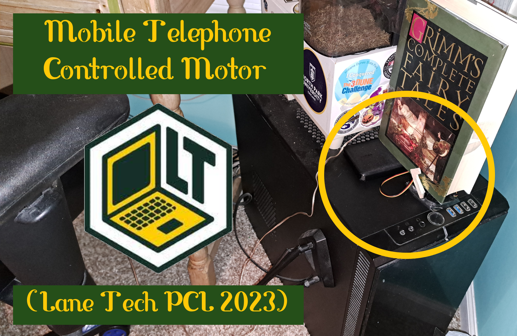
Have you ever wanted to press down a button or turn a switch remotely from your phone? With this project you can!
All it takes is some electrical engineering and some programming skills to assemble a Particle Argon micro-controller, wires, a small servo motor, a wooden arm, and a button into a working project.
I created this project for the Home Automation Project in my Physical Computing Laboratory class in my junior year at Albert G. Lane Technicial High School. The Home Automation project required students to create a simple microcontroller circuit that would automate some part of his or her house. I used my project to access my computer easier; it takes a long time to boot up, so if I could turn on my computer before I got to my room, I could use it earlier.
Obviously, everyone will not have the same exact model of computer with the same button as I do, but the controlled servo could have a use for someone else with a small amount of tweaking.
Here's a slideshow that I made of my project that narrates the process I went through to complete the project and the many challenges I had to over come.
Supplies
Prerequisites
- Access to a mobile smart telephone running IOS (AND ONLY IOS!)
- Personal computer
- Wi-Fi connection
- Constant power source, either from an outlet or an external battery pack
Skills
- Basic knowledge of soldering and cutting and stripping of wires
- Basic knowledge of wiring and electrical engineering
- Programming knowledge of C++ (although Java is very similar and can be substituted)
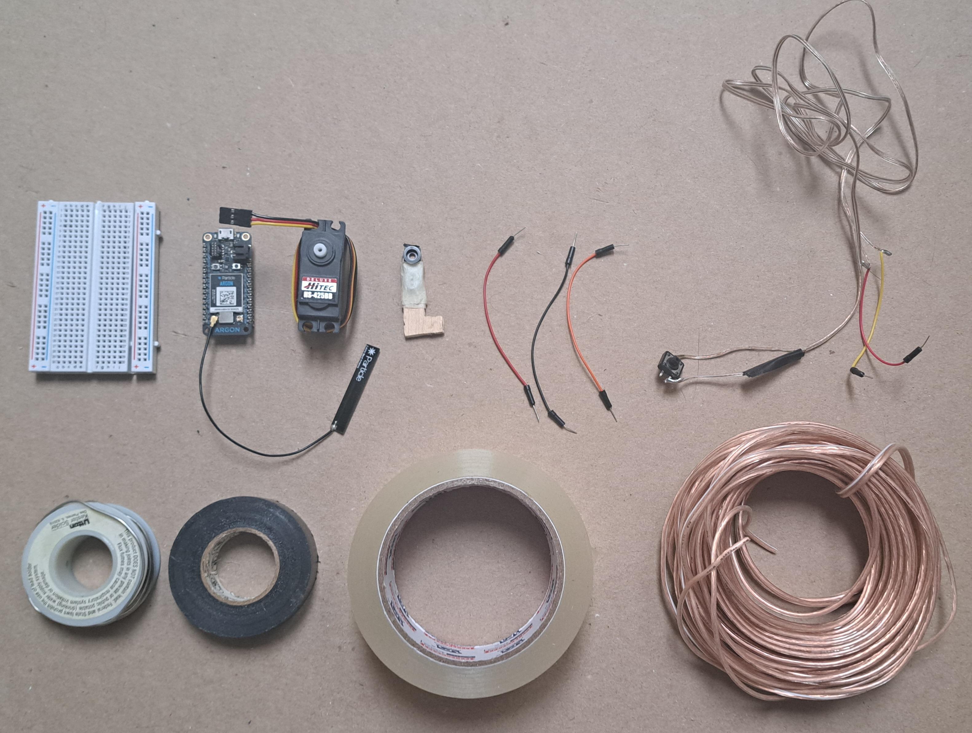
Supplies
First image, left to right
- Bread board
- Particle Argon (and Micro USB power cable; with wall outlet adapter, if needed)
- small servo motor with 3 female wires (compatible with male jumper wires)
- servo motor arm (comes with the motor usually) and a small piece of thin wood
- Five short male/male jumper wires
- Small button
- Solder
- Packing tape
- Electrical Tape
- Appropriate length of dual stranded insulated wire
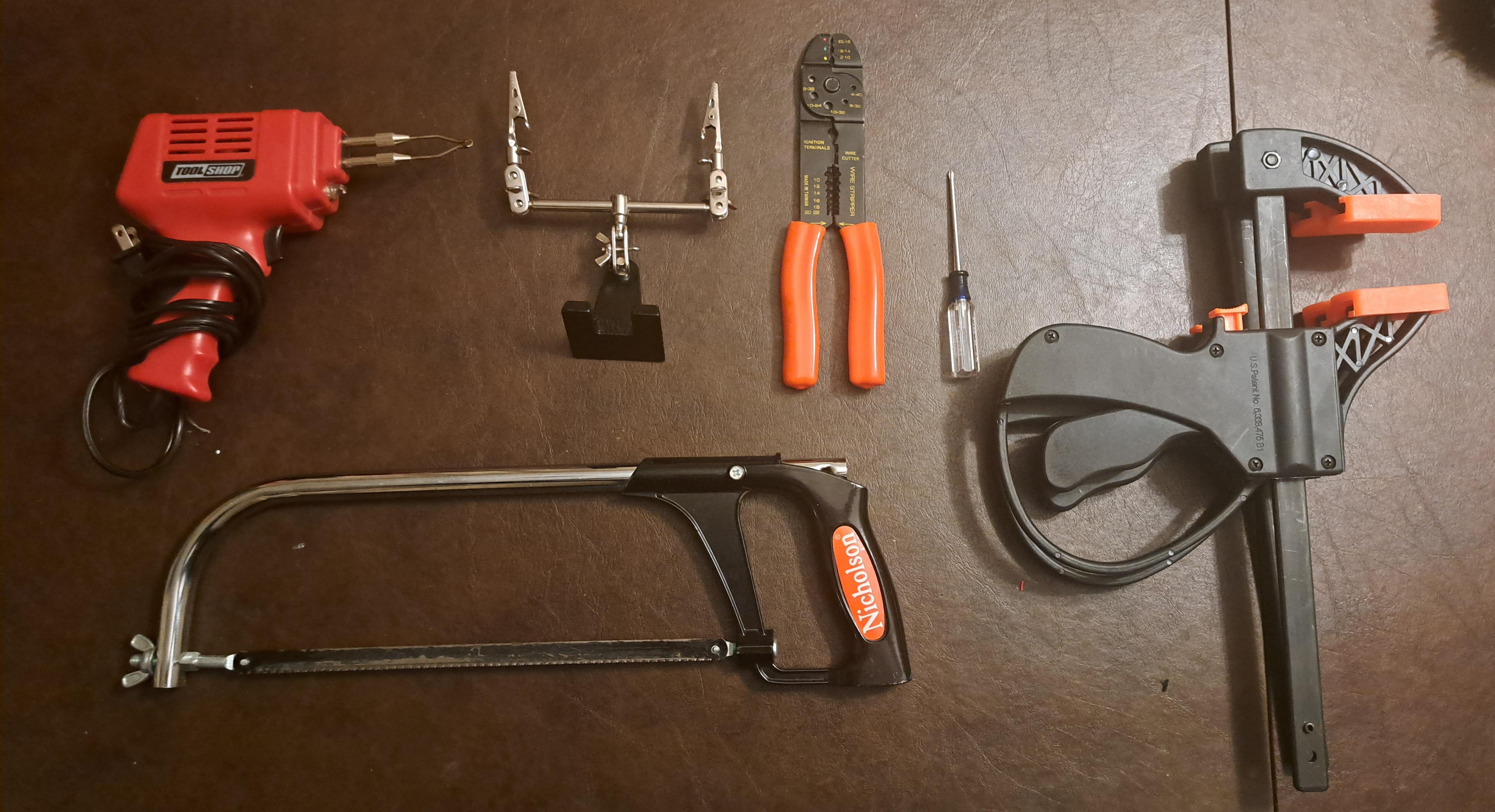
Tools
Second image, left to right
- Soldering gun
- Soldering hands
- Wire stripper and wire cutter
- Screw driver
- Clamps
- Hand saw
- Hot glue gun (not pictured)
- Hot glue (not pictured)
- Thin blade (knife or boxcutter, not pictured)
Accounts
- Particle IOT account
- Particle IOT telephone application (Warning: Not Available on Google Play!)
- IFTTT account
- IFTTT telephone application (IOS version)
Software
In order to execute this project, you will need to first set up your Particle Argon device and pair it with your Particle IOT account. In order to pair your device with your account, you will need to have the Particle IOT application installed on a smart telephone that is running IOS. The application should have sufficient instructions on how to do this, but a step-by-step guide can be found here.
The first step will be to create the soft ware back end. This involves two components: the C++ code that will control the Argon and the hard ware that will be connected to it, and the IFTTT applet and web hook that will be used to send signals from your mobile telephone to the Argon.
C++ Code
My code file, for reference. I've also attached it at the bottom of the page.
1. Log into the Particle Web IDE web site, it should have a blank file already loaded. If it doesn't, click on the "Create New App" button.
Give your file a title of your choice, and then save it by clicking the manilla folder icon in the upper far right corner of the web site. This will allow you to return to your file later.
2. Your file should already have a blank setup function and blank loop function. Don't remove these. Above the setup function, create a Servo variable with no value, an int variable for your button set to D7 (digital pin 7 of the Argon), and another int variable set to 0.
Servo myServo;
int btn = D7;
int msHeld = 0;

void setup() {

}

void loop() {

}
4. Now we will move on to the setup function. This function runs once when your program initializes.
Set the pinMode of your button variable to INPUT_PULLUP. This is necessary because it enables an internal resistor that eliminates any electrical interference from the button.
Attach your servo variable to 8 (digital pin 8 of the Argon). Then write the servo variable to 10 degrees, this will make it turn to 10 degrees whenever your program starts.
You then want to expose two functions that we haven't written yet. The second function is specific to my situtation of pressing my computers button down, and you may not need to use it. However, the first function will be necessary. You will need an event name and a function name for both functions. The event name is in quotation marks and what we will call from the mobile phone.
Servo myServo;
int btn = D7;
int msHeld = 0;

void setup() {
    pinMode(btn, INPUT_PULLUP);
    myServo.attach(8);
    myServo.write(10);

    Particle.function("onHook", computerOn);
    Particle.function("offHook", computerOff);
}

void loop() {

}
5. Now we will fill in the loop function. This is where all of the setup we have done will be utilized. The specifics of this code is tailored to my computer and its button. My computer's button is unique in that a small press will turn it on, but holding it down for 6 seconds will turn it off. The code that I will show you how to implement below will emulate that function: Pressing down the button on the argon without holding it down will trigger the function that has the motor lightly press the button, thereby turning the computer on. Holding down the button for more than 400 milliseconds will trigger the function that has the motor hold down the button, thereby turning the computer off.
Firstly we will create a for loop that will run for 10 iterations.
When the for loop runs, if the button is pressed down, we increment the msHeld variable by 100. If the button is not pressed down, we break the for loop (but not the loop() function itself.) At the end of the for loop, we wait 0.1 seconds.
What the above for loop did was to count the number of millseconds within the 1 second that the button was being held down for, because if the loop runs 10 times and each time delays 100 milliseconds, that will add up to 1 seconds. If the user stopped holding down the button, the loop terminates, which means that only the amount of time that they were holding down the button for was recorded by msHeld, not the full 1 second that the loop runs for.
Servo myServo;
int btn = D7;
int msHeld = 0;

void setup() {
    pinMode(btn, INPUT_PULLUP);
    myServo.attach(8);
    myServo.write(10);

    Particle.function("onHook", computerOn);
    Particle.function("offHook", computerOff);
}

void loop() {
    for (int i = 0; i < 10; i++) {
        if (digitalRead(btn) == LOW) {
            msHeld = msHeld + 100;
        } else if (digitalRead(btn) == HIGH) {
        break;
        }
        delay(100);
    }
}
Now we will use the msHeld variable that we just measured. If the milliseconds held was less than 400 but greater than 0, we will call the computerOn function. If the milliseconds held was greater than 400 but less than equal to 1000 (1 second), we will call the computerOff function.
At the end of the loop() function we will reset the msHeld variable to 0. If the button wasn't pressed at all, nothing is caused and the loop resets, waiting for the button to be pressed down or held down.
Servo myServo;
int btn = D7;
int msHeld = 0;

void setup() {
    pinMode(btn, INPUT_PULLUP);
    myServo.attach(8);
    myServo.write(10);

    Particle.function("onHook", computerOn);
    Particle.function("offHook", computerOff);
}

void loop() {
    for (int i = 0; i < 10; i++) {
        if (digitalRead(btn) == LOW) {
            msHeld = msHeld + 100;
        } else if (digitalRead(btn) == HIGH) {
        break;
        }
        delay(100);
    }
    if (msHeld < 400 && msHeld > 0) {
        computerOn("param");
    }

    else if (msHeld > 400 && msHeld  <= 1000) {
        computerOff("param");
    }

    msHeld = 0;
}
6. Now we will define the two functions that we have referenced already. Both functions do almost the same thing, except computerOff holds the button down for four seconds. These functions will not be included inside of the loop() function.
We define a new function that returns an int called computerOn with a single String argument. This string argument is needed but we will not use it at all. We will create a for loop within the function that turns the servo 170 degrees from the starting 10 degrees. with a delay of 1 millesecond for each degree turned, holds it down for 1.5 seconds, and then turns back. Then we wait for 100 milliseconds and then return 0. The int that we return is not relevant to our program, but we still need to include it.
The way that the loop works is that it iterates for every degree the servo has to turn to make it to 170 degrees from 10. That means that the servo turns more fluidly than just turning to 170 degrees from 10, it turns to 11, 12, 13, 14, and so on instead.
Servo myServo;
int btn = D7;
int msHeld = 0;

void setup() {
    pinMode(btn, INPUT_PULLUP);
    myServo.attach(8);
    myServo.write(10);

    Particle.function("onHook", computerOn);
    Particle.function("offHook", computerOff);
}

void loop() {
    for (int i = 0; i < 10; i++) {
        if (digitalRead(btn) == LOW) {
            msHeld = msHeld + 100;
        } else if (digitalRead(btn) == HIGH) {
        break;
        }
        delay(100);
    }
    if (msHeld < 400 && msHeld > 0) {
        computerOn("param");
    }

    else if (msHeld > 400 && msHeld  <= 1000) {
        computerOff("param");
    }

    msHeld = 0;
}

int computerOn(String param) {


        for(int pos = 10; pos <= 170; pos++)
        {
            myServo.write(pos);
            delay(1);
        }
        delay(1500);
        for(int pos = 170; pos >= 10; pos--)
        {
            myServo.write(pos);
            delay(1);
        }
        delay(100);
        return 0;
}
We will then make the computerOff function, the same exact function as above except this one holds down for 6 seconds instead of 1.5.
Servo myServo;
int btn = D7;
int msHeld = 0;

void setup() {
    pinMode(btn, INPUT_PULLUP);
    myServo.attach(8);
    myServo.write(10);

    Particle.function("onHook", computerOn);
    Particle.function("offHook", computerOff);
}

void loop() {
    for (int i = 0; i < 10; i++) {
        if (digitalRead(btn) == LOW) {
            msHeld = msHeld + 100;
        } else if (digitalRead(btn) == HIGH) {
        break;
        }
        delay(100);
    }
    if (msHeld < 400 && msHeld > 0) {
        computerOn("param");
    }

    else if (msHeld > 400 && msHeld  <= 1000) {
        computerOff("param");
    }

    msHeld = 0;
}

int computerOn(String param) {


        for(int pos = 10; pos <= 170; pos++)
        {
            myServo.write(pos);
            delay(1);
        }
        delay(1500);
        for(int pos = 170; pos >= 10; pos--)
        {
            myServo.write(pos);
            delay(1);
        }
        delay(100);
        return 0;
}

int computerOff(String param) {

    for(int pos = 10; pos <= 170; pos++)    {
        myServo.write(pos);
        delay(1);
    }
    delay(6000);
    for(int pos = 170; pos >= 10; pos--)
    {
        myServo.write(pos);
        delay(1);
    }
    delay(100);
    return 0;
}
Now the code is finished. Click on save and remember your username and password, we will need this later.
IFTTT Connection
We will now use IFTTT, which you should already have an account for and the application downloaded, to connect the mobile telephone to the Argon. In order to do this, we will need to create a "webhook", that is, a publicly accessible URL that calls a function on your Argon. To do this we need to gain three things: your device's ID, an access token for your device, and the event name of the function that you are going to call.
https://api.particle.io/v1/devices/DEVICE_ID/EVENTNAME?access_token=ACCESSTOKEN
Finding the device ID is easy, log into the Particle Console website and go to the devices tab. Your device should be listed, along with its ID. (the X's represent your device's ID)
https://api.particle.io/v1/devices/XXXXXXXXXXXXXXXXXXXXXXX/EVENTNAME?access_token=ACCESSTOKEN
Now we will get the access token. Doing this is slightly harder. An access token doesn't exist by default, so we have to create one. Log into the Particle Documentation website and go the entry for Access Tokens. On this page is a section titled "Creating an Access Token (browser-based)". Go to that section, and create an access token that will never expire. You need your username and password for this. Make sure to save that token in a safe space. Now you can fill in the link like this: (the Y's represent your access token)
https://api.particle.io/v1/devices/XXXXXXXXXXXXXXXXXXXXXXX/EVENTNAME?access_token=YYYYYYYYYYYYYYYYYYYYYYYYYYYYYYYYYYYYYYY
The event name is the simplest to get out of the three, it is the word in quotation marks in the Particle.Function call that we did in setup for both computerOn (onHook) and computerOff (offHook). Now you should have two links that look like this: (Obviously the X's and Y's should be your device ID and access token)
https://api.particle.io/v1/devices/XXXXXXXXXXXXXXXXXXXXXXX/onHook?access_token=YYYYYYYYYYYYYYYYYYYYYYYYYYYYYYYYYYYYYYY
https://api.particle.io/v1/devices/XXXXXXXXXXXXXXXXXXXXXXX/offHook?access_token=YYYYYYYYYYYYYYYYYYYYYYYYYYYYYYYYYYYYYYY
IFTTT Applet
The link we created above will be what we will use to link IFTTT to our Argon. Now we are going to log into the IFTTT website or launch the mobile application, either works for this stage. Once you are at the homepage you can click on the "Create" button in the upper right corner of the page. This will take you to the interface to create an applet. Add to "If This" the "Button Widget." You will need to search for it. Select "button press" as the trigger. Add to "Then That" a "Webhook." You will need to search for this as well. In the URL section, copy the URL that you created earlier. Set the method to "Post" and the content type to "application/json." Leave the other fields blank.
Repeat the above process for the computerOff function and associated link as well.
Now that you have created your IFTTT applets, you can add the widgets to the home screen of your mobile telephone. Go to "My Applets" in the IFTTT application and select them one at a time. In the menu, press "add to home screen." Do this for both applets. You should see two blue buttons now on the home screen of your telephone. They do not work yet, because we haven't created the hardware.
Now we have finished all of the software needed for this project.
Hardware
In order to combine all of the pieces of hardware on the breadboard, we will need to first assemble the individual components.
1. The first step is to create the wire for the button. This wire will be long in order to provide flexibility for its location. Measure out the needed amount of dual stranded insulated wire and cut it with the wire cutter. Take the thin blade and split the wire for around 3 inches at both ends. You should have a length of the two wires bonded to each other, and then three inches of it split at both ends. Take the wire stripper and strip both strands of the wire at both ends so that the stripped portions are around an inch long.
Take two of the five male/male jumper wires and cut off their pins at one end (and one end only). Then strip the wire at the cut end so that the stripped portion is about an inch.
You will now need to solder four connections. Take the two jumper wires and wrap them around one end of the dual stranded wire each. Use the soldering hands to hold these two strands of tied wires in place while you solder the connection using the soldering gun and the solder.
Wait for that to dry.
Once it is dried, take your small button and wrap the other ends of the dual stranded wire around opposite pins on the button. You should have each strand wrapped around a different side. Take the solder and use the soldering gun to solder those two connections. You can disregard the other two pins on the button.
Now you should have a wire that looks similar to the wire in my supplies image.
2. The second step is to create a wooden arm that will be bonded to the servo's arm. The specifications will vary from person to person, but I made a arm around 2 inches long with a 1 cm long outcropping, forming an L. I did this by taking the thin piece of wood, clamping it down, and sawing it with the hand saw until it met my specifications. Take a plastic arm (that comes with your servo motor and can connect to it) that has a limb that is around an inch long. Cut that arm until it resembles a rectangle with the connector at the end. You may not need to do this. I then used the hot glue gun and the hot glue to bind the wooden piece to the plastic, and then the electric tape to strengthen the bond.
Connect this combined arm to your servo motor. It should fit nicely onto the circular extension.
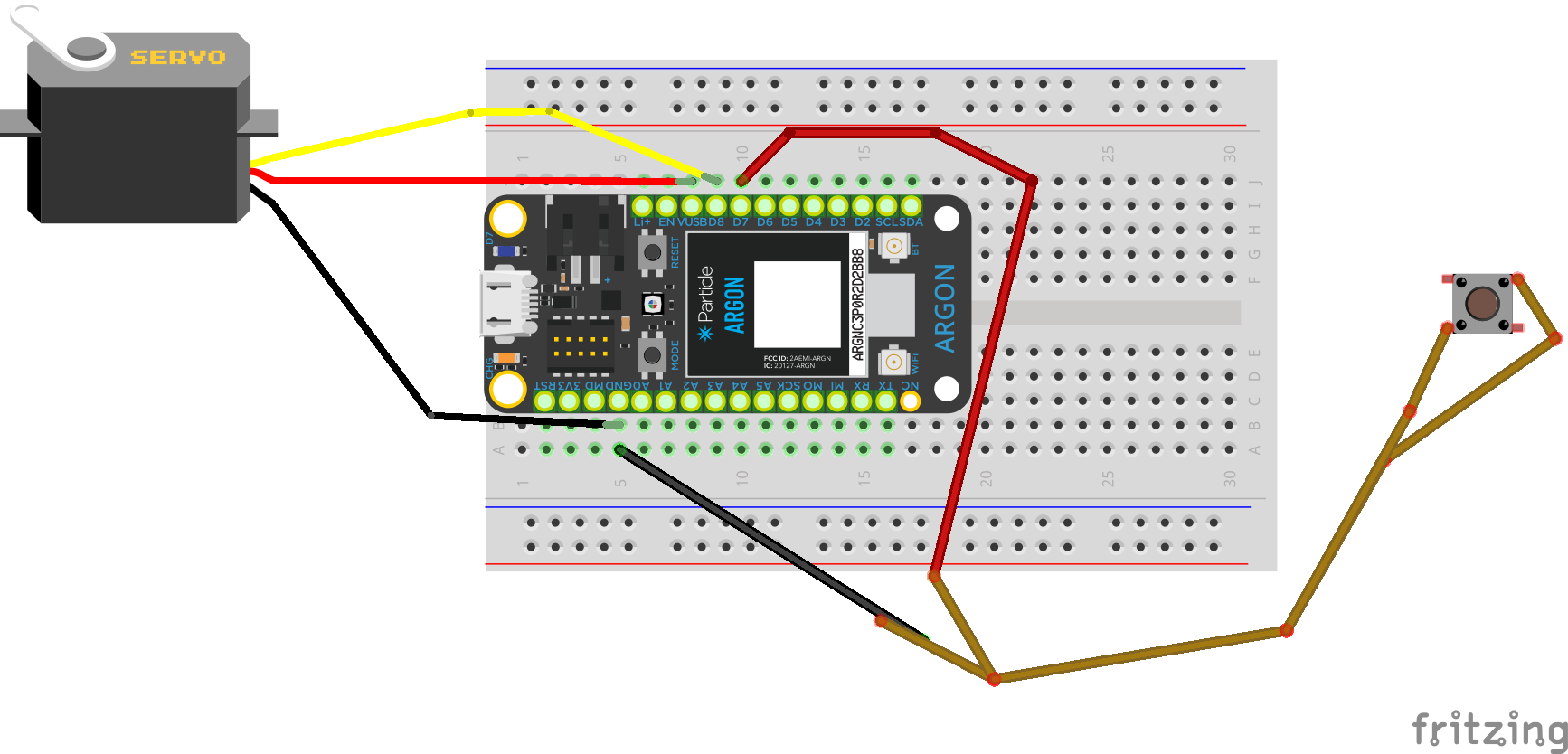
3. Now you will wire everything onto your breadboard.
First step is to connect your Argon to the breadboard. Press it firmly down on one of the short edges of the board until it can't go any further. Make sure there is two holes lined up to the "GND" pin on the left side of the Argon. The wiring should be according to the diagram provided above. Make sure that the jumper wire extending from the yellow female wire on the servo motor is plugged into D8 on the right side of the argon, and one of the jumper wires from the button is plugged into D7 on the right side of the argon. This is in accordance with the programming we did above. When all of your wires are connected as it shows on the diagram, the project is almost finished. Our next step is to test the program!
Testing
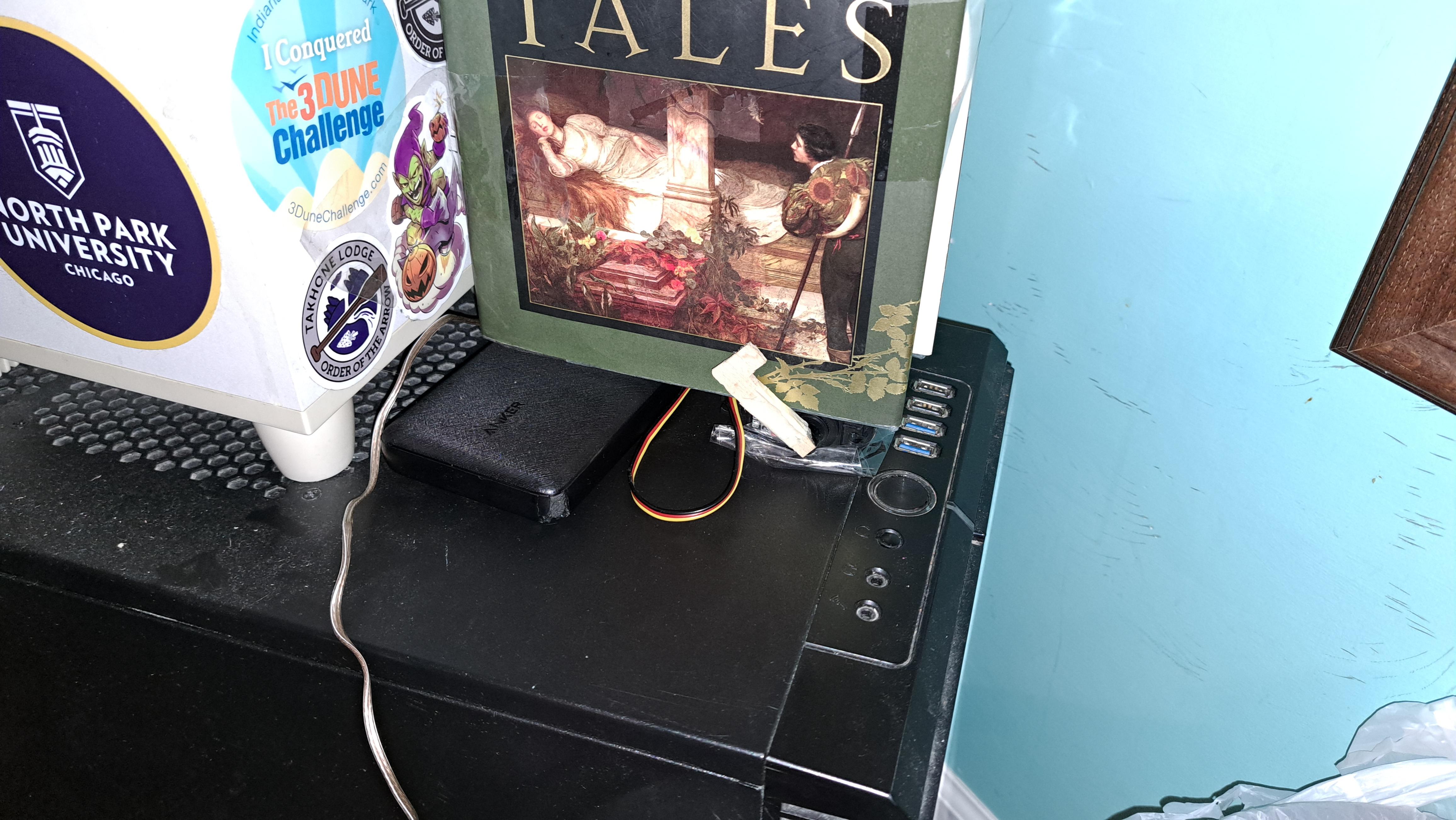
Attached video of the project mounted and working for my computer
Plug in your Argon to a power source and then log into the Web IDE. Go to your file and click the lightning bolt shaped icon on the right side menu to "flash" your code to your Argon. Once your argon is again flashing blue, try to push the button and trigger the IFTTT applet, it should work! If it doesn't go over the instructions again to make sure you did everything right.
Thank you for reading my instructable!