Remote Cat Door Unlocker


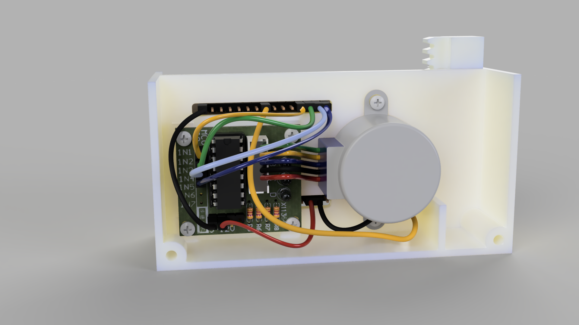
The project uses a web page hosted on the 8266 to provide a WEB UI to lock and unlock a cat door. You can also activate the door with a button on the module itself. The design utilizes a 3D-printed chassis and rack and pinion to lock the door. Check out the videos below for full details
Supplies
1 × Stepper motor and driver https://amzn.to/3TSGy88
1 × ESP8266 NodeMCU CP2102 ESP-12E https://amzn.to/3Wd1Mzc
2 × Momentary Tactile Tact Push Button Switch https://amzn.to/3t0RMvH
All STLs can be found here: https://jasonwinfield.nz/my-stls/
Print STL Files
Print the STL files found here: https://jasonwinfield.nz/my-stls/ No supports should be required, I would suggest 100% infill around mounting holes if your slicer allows this but it is not imperative.
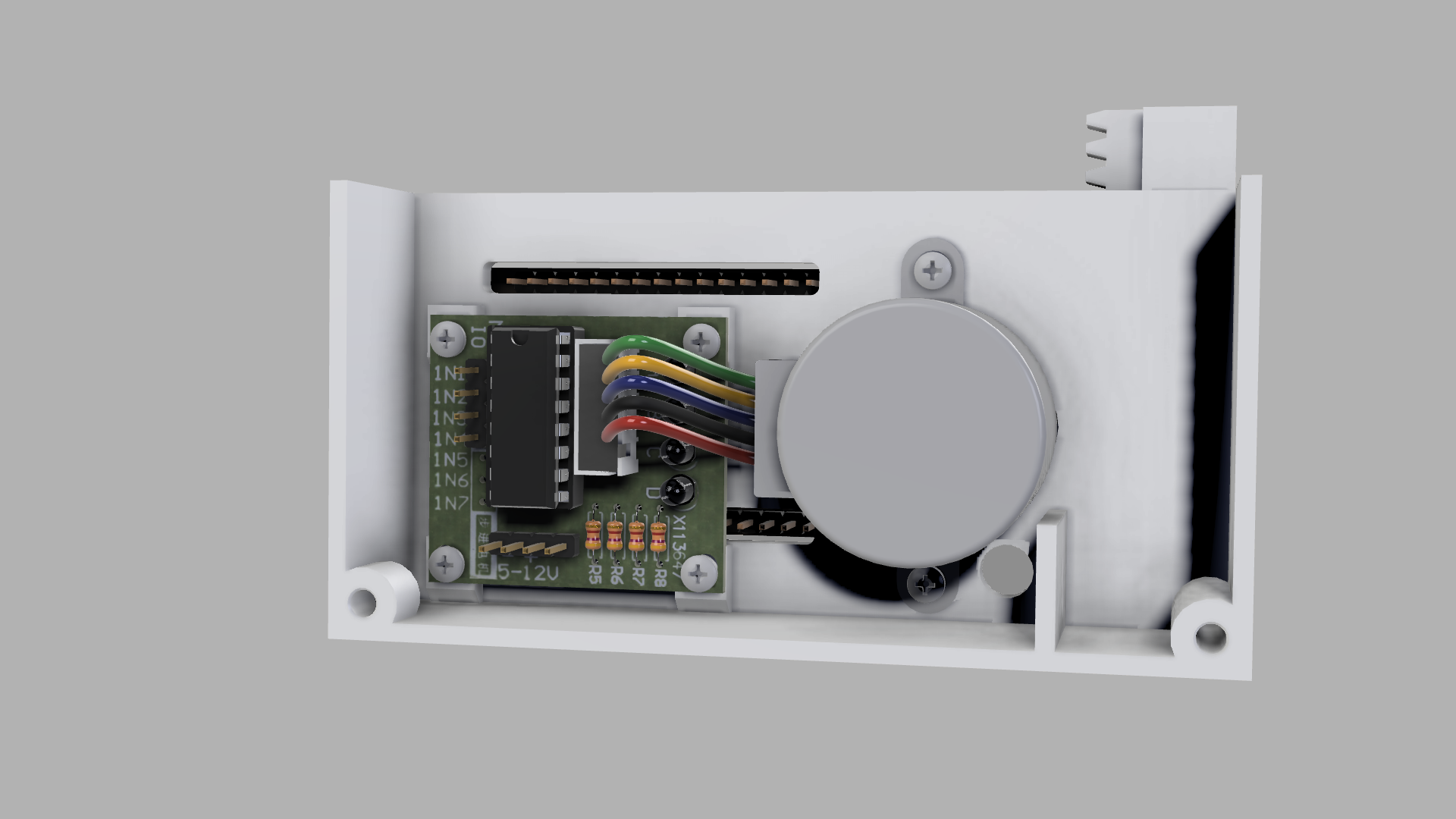
Screw in the Motor and Driver.
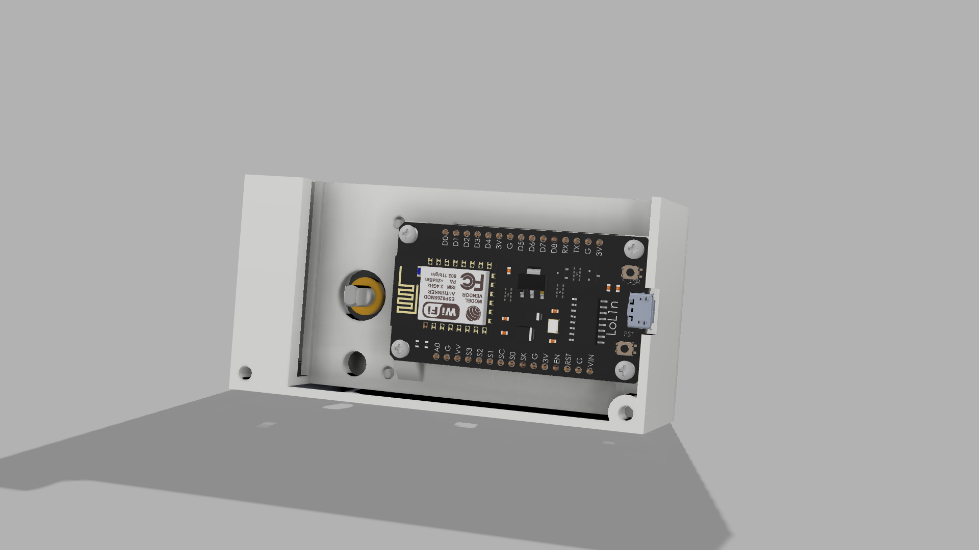
Install the 8266 Controller
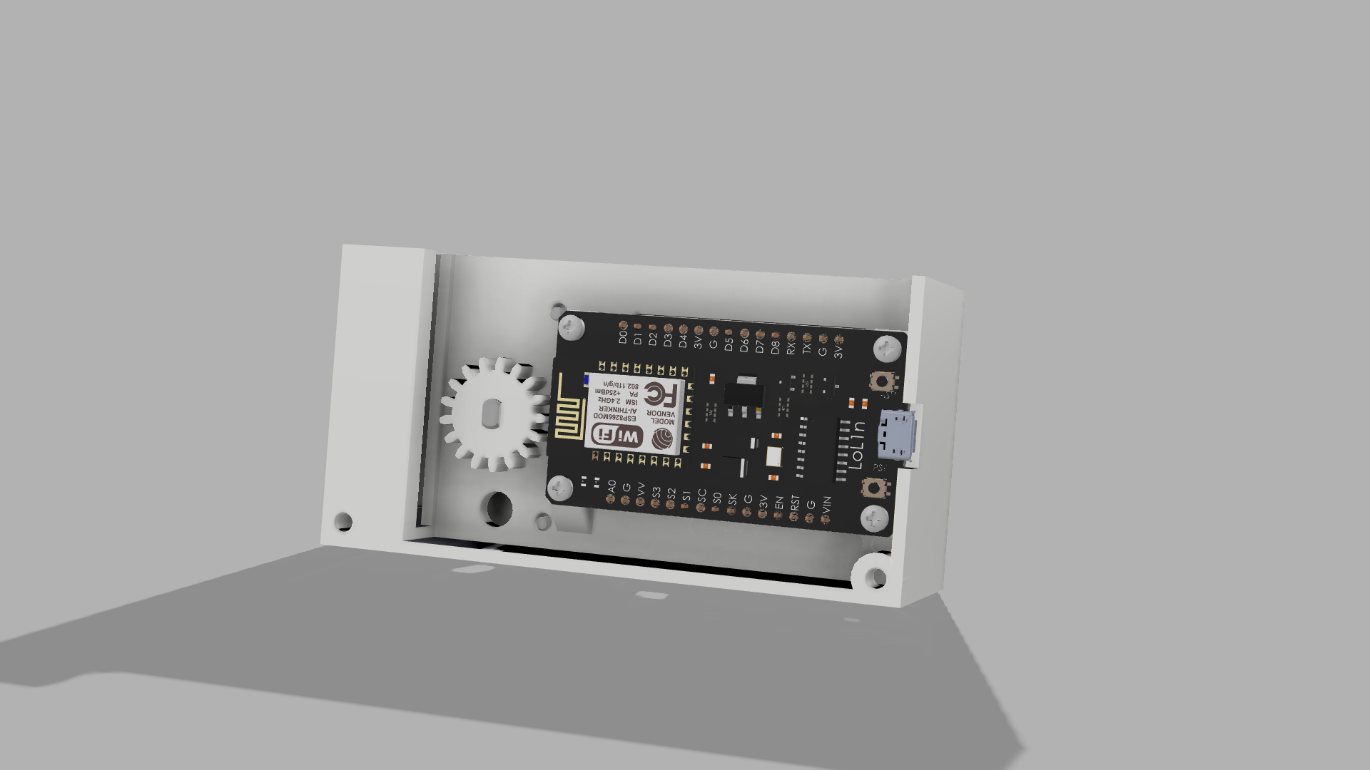
Install Spur Gear
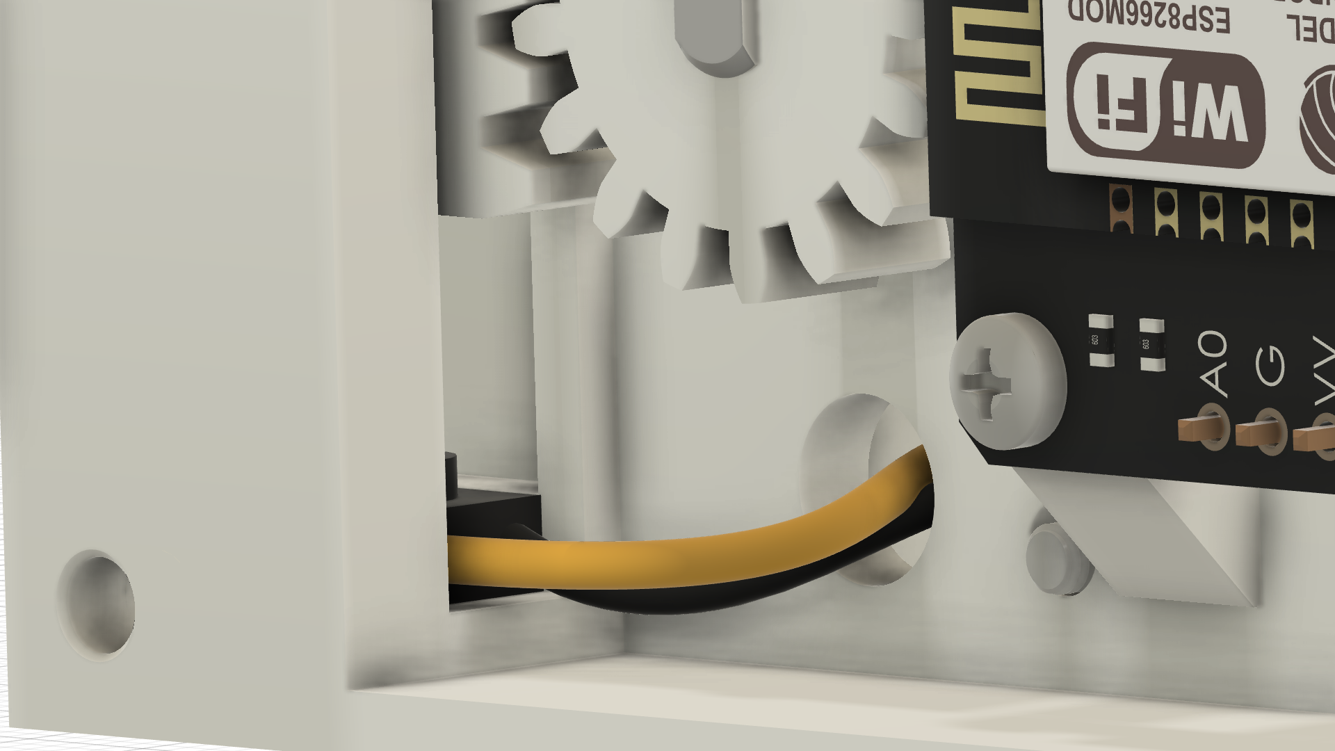
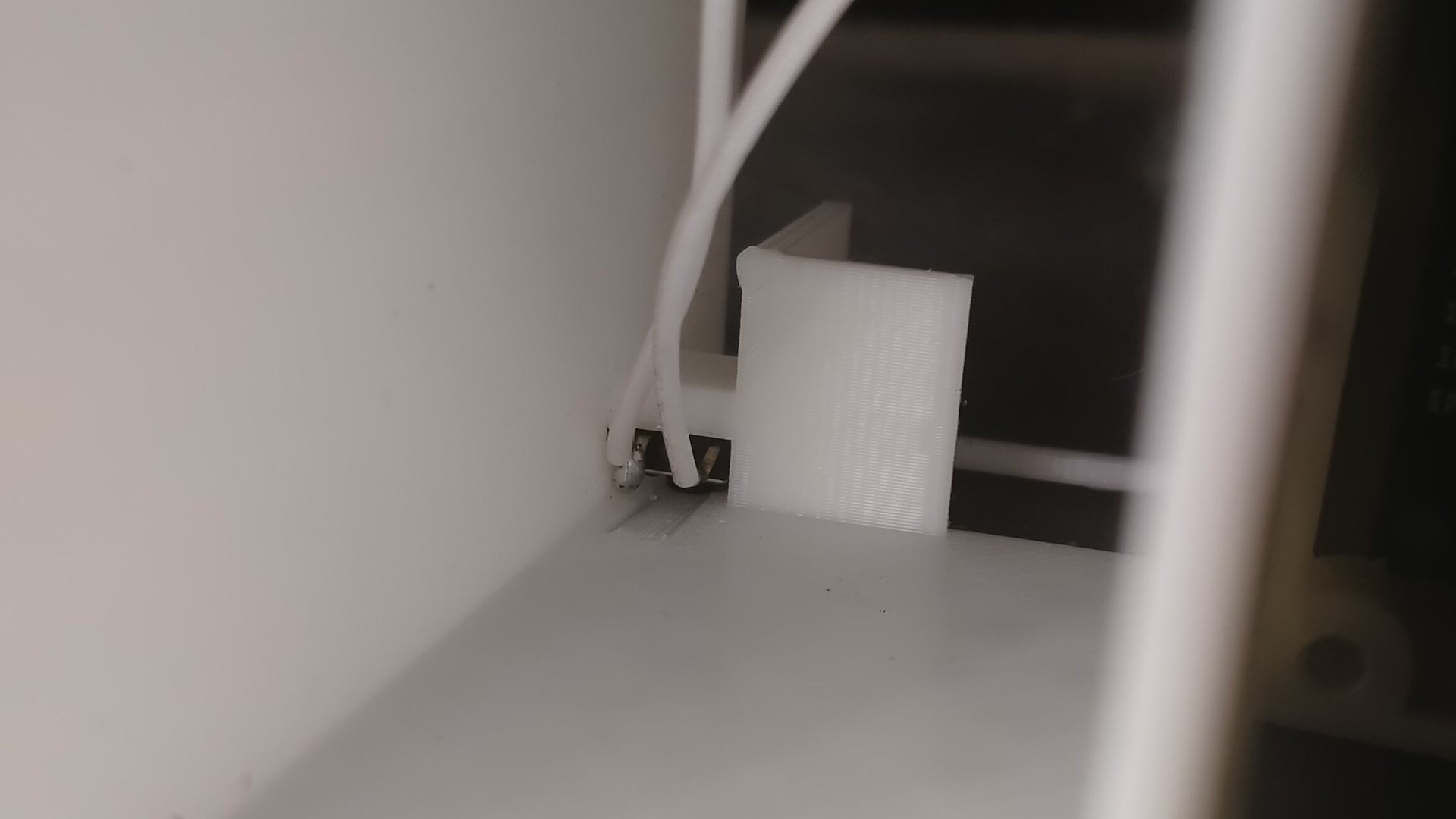
Install the Lower Limit Switch
Install the Remaining Wiring Between the Motor Controller and Motor
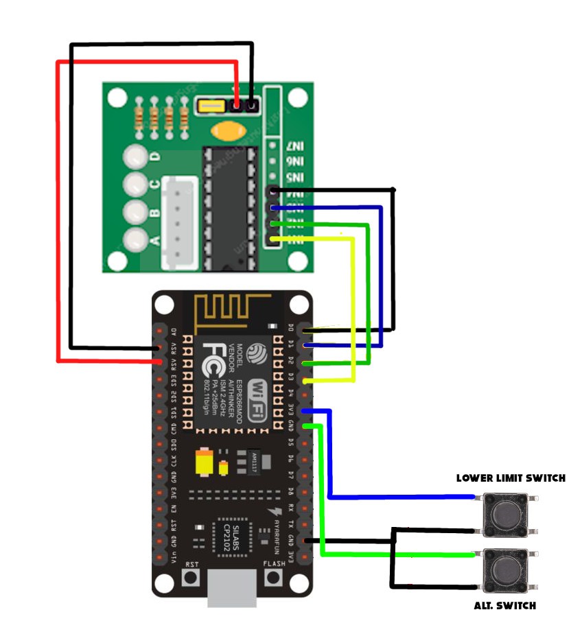
Install the motor controller and lower limit switch wiring as shown in the guide, Pay particular attention to the order of the wires for the motor.
You can also connect the lower limit switch. Note that the pin between the lower limit switch and the input for the limit switch is a 3.3v supply make sure you do not accidentally connect this switch across 3.3v and GND (don't ask how I know).
Install ALT Switch
Install Code
Copy and paste the following code into the Arduino IDE. Update the AP name and password to match your needs.
90% of this code is not mine. For full details please see this great guide: https://randomnerdtutorials.com/esp32-esp8266-web-server-physical-button/
// Import required libraries
#ifdef ESP32
  #include <WiFi.h>
  #include <AsyncTCP.h>
#else
  #include <ESP8266WiFi.h>
  #include <ESPAsyncTCP.h>
#endif
#include <ESPAsyncWebServer.h>

#define STEPPER_PIN_1 0
#define STEPPER_PIN_2 4
#define STEPPER_PIN_3 5
#define STEPPER_PIN_4 16
int step_number = 0;

int lowerLimitState =1;

// Replace with your network credentials
const char* ssid = "YOURAP";
const char* password = "YOURAP_PASSWORD!";
const char* PARAM_INPUT_1 = "state";
const int lowerLimit = 14;
const int output = 2;
const int buttonPin = 12;

// Variables will change:
int ledState = LOW;          // the current state of the output pin
int buttonState;             // the current reading from the input pin
int lastButtonState = LOW;   // the previous reading from the input pin
int driveUpTime = 1000;      // how long the motor should drive up for
int upperTime=0;

// Create AsyncWebServer object on port 80
AsyncWebServer server(80);

const char index_html[] PROGMEM = R"rawliteral(
<!DOCTYPE HTML><html>
<head>
  <title>Cat door lock</title>
  <meta name="viewport" content="width=device-width, initial-scale=1">
  <style>
    html {font-family: Arial; display: inline-block; text-align: center;}
    h2 {font-size: 3.0rem;}
    p {font-size: 3.0rem;}
    body {max-width: 600px; margin:0px auto; padding-bottom: 25px;}
    .switch {position: relative; display: inline-block; width: 120px; height: 68px}
    .switch input {display: none}
    .slider {position: absolute; top: 0; left: 0; right: 0; bottom: 0; background-color: #ccc; border-radius: 34px}
    .slider:before {position: absolute; content: ""; height: 52px; width: 52px; left: 8px; bottom: 8px; background-color: #fff; -webkit-transition: .4s; transition: .4s; border-radius: 68px}
    input:checked+.slider {background-color: #2196F3}
    input:checked+.slider:before {-webkit-transform: translateX(52px); -ms-transform: translateX(52px); transform: translateX(52px)}
  </style>
</head>
<body>
  <h2>Tap to unlock</h2>
  %BUTTONPLACEHOLDER%
<script>function toggleCheckbox(element) {
  var xhr = new XMLHttpRequest();
  if(element.checked){ xhr.open("GET", "/update?state=1", true); }
  else { xhr.open("GET", "/update?state=0", true); }
  xhr.send();
}

setInterval(function ( ) {
  var xhttp = new XMLHttpRequest();
  xhttp.onreadystatechange = function() {
    if (this.readyState == 4 && this.status == 200) {
      var inputChecked;
      var outputStateM;
      if( this.responseText == 1){
        inputChecked = true;
        outputStateM = "On";
      }
      else {
        inputChecked = false;
        outputStateM = "Off";
      }
      document.getElementById("output").checked = inputChecked;
      document.getElementById("outputState").innerHTML = outputStateM;
    }
  };
  xhttp.open("GET", "/state", true);
  xhttp.send();
}, 1000 ) ;
</script>
</body>
</html>
)rawliteral";

// Replaces placeholder with button section in your web page
String processor(const String& var){
  //Serial.println(var);
  if(var == "BUTTONPLACEHOLDER"){
    String buttons ="";
    String outputStateValue = outputState();
    //buttons+="<h4>Output - GPIO 2 - State <span id=\"outputState\"></span></h4><label class=\"switch\"><input type=\"checkbox\" onchange=\"toggleCheckbox(this)\" id=\"output\" " + outputStateValue + "><span class=\"slider\"></span></label>";
    buttons+="<h4><span id=\"outputState\"></span></h4><label class=\"switch\"><input type=\"checkbox\" onchange=\"toggleCheckbox(this)\" id=\"output\"><span class=\"slider\"></span></label>";

    return buttons;
  }
  return String();
}

String outputState(){
  if(digitalRead(output)){
    return "checked";
  }
  else {
    return "";
  }
  return "";
}

void setup(){
  // Serial port for debugging purposes
  Serial.begin(115200);
  pinMode(output, OUTPUT);
  digitalWrite(output, LOW);
  pinMode(buttonPin, INPUT_PULLUP);
  pinMode(lowerLimit, INPUT_PULLUP);
  pinMode(STEPPER_PIN_1, OUTPUT);
  pinMode(STEPPER_PIN_2, OUTPUT);
  pinMode(STEPPER_PIN_3, OUTPUT);
  pinMode(STEPPER_PIN_4, OUTPUT);

  // Connect to Wi-Fi
  WiFi.begin(ssid, password);
  while (WiFi.status() != WL_CONNECTED) {
    delay(1000);
    Serial.println("Connecting to WiFi..");
  }

  // Print ESP Local IP Address
  Serial.println(WiFi.localIP());

  // Route for root / web page
  server.on("/", HTTP_GET, [](AsyncWebServerRequest *request){
    request->send_P(200, "text/html", index_html, processor);
  });

  // Send a GET request to <ESP_IP>/update?state=<inputMessage>
  server.on("/update", HTTP_GET, [] (AsyncWebServerRequest *request) {
    String inputMessage;
    String inputParam;
    // GET input1 value on <ESP_IP>/update?state=<inputMessage>
    if (request->hasParam(PARAM_INPUT_1)) {
      inputMessage = request->getParam(PARAM_INPUT_1)->value();
      inputParam = PARAM_INPUT_1;
      digitalWrite(output, inputMessage.toInt());
      ledState = !ledState;
    }
    else {
      inputMessage = "No message sent";
      inputParam = "none";
    }
    Serial.println(inputMessage);
    request->send(200, "text/plain", "OK");
  });

  // Send a GET request to <ESP_IP>/state
  server.on("/state", HTTP_GET, [] (AsyncWebServerRequest *request) {
    request->send(200, "text/plain", String(digitalRead(output)).c_str());
  });
  // Start server
  server.begin();
initilaize();
}

void loop() {

int buttonState = digitalRead(buttonPin);
      if (buttonState == LOW) {
        ledState = !ledState;
    }
  digitalWrite(output, ledState);
  if (ledState)
  {
    lockDoor();
   upperTime=0;
  }
}

void lockDoor()
{
 lowerLimitState=digitalRead(lowerLimit);
 upperTime=0;
  Serial.println("driveMotor");
 while (lowerLimitState!=0)
  {
    lowerLimitState=digitalRead(lowerLimit);
    OneStep(false);
    delay(2);
  }

 delay(10000);

  while (upperTime!=driveUpTime)
  {
    upperTime++;
    OneStep(true);
    delay(2);
  }

  digitalWrite(STEPPER_PIN_1, LOW);
  digitalWrite(STEPPER_PIN_2, LOW);
  digitalWrite(STEPPER_PIN_3, LOW);
  digitalWrite(STEPPER_PIN_4, LOW);
  ledState = !ledState;
}

void initilaize()
{
  lowerLimitState=digitalRead(lowerLimit);
  while (lowerLimitState!=0)
  {
    lowerLimitState=digitalRead(lowerLimit);
    OneStep(false);
    delay(2);
  }
  while (upperTime!=driveUpTime)
  {
    upperTime++;
    OneStep(true);
    delay(2);
  }


  digitalWrite(STEPPER_PIN_1, LOW);
  digitalWrite(STEPPER_PIN_2, LOW);
  digitalWrite(STEPPER_PIN_3, LOW);
  digitalWrite(STEPPER_PIN_4, LOW);
}


void OneStep(bool dir){
    if(dir){
switch(step_number){
  case 0:
  digitalWrite(STEPPER_PIN_1, HIGH);
  digitalWrite(STEPPER_PIN_2, LOW);
  digitalWrite(STEPPER_PIN_3, LOW);
  digitalWrite(STEPPER_PIN_4, LOW);
  break;
  case 1:
  digitalWrite(STEPPER_PIN_1, LOW);
  digitalWrite(STEPPER_PIN_2, HIGH);
  digitalWrite(STEPPER_PIN_3, LOW);
  digitalWrite(STEPPER_PIN_4, LOW);
  break;
  case 2:
  digitalWrite(STEPPER_PIN_1, LOW);
  digitalWrite(STEPPER_PIN_2, LOW);
  digitalWrite(STEPPER_PIN_3, HIGH);
  digitalWrite(STEPPER_PIN_4, LOW);
  break;
  case 3:
  digitalWrite(STEPPER_PIN_1, LOW);
  digitalWrite(STEPPER_PIN_2, LOW);
  digitalWrite(STEPPER_PIN_3, LOW);
  digitalWrite(STEPPER_PIN_4, HIGH);
  break;
}
  }else{
    switch(step_number){
  case 0:
  digitalWrite(STEPPER_PIN_1, LOW);
  digitalWrite(STEPPER_PIN_2, LOW);
  digitalWrite(STEPPER_PIN_3, LOW);
  digitalWrite(STEPPER_PIN_4, HIGH);
  break;
  case 1:
  digitalWrite(STEPPER_PIN_1, LOW);
  digitalWrite(STEPPER_PIN_2, LOW);
  digitalWrite(STEPPER_PIN_3, HIGH);
  digitalWrite(STEPPER_PIN_4, LOW);
  break;
  case 2:
  digitalWrite(STEPPER_PIN_1, LOW);
  digitalWrite(STEPPER_PIN_2, HIGH);
  digitalWrite(STEPPER_PIN_3, LOW);
  digitalWrite(STEPPER_PIN_4, LOW);
  break;
  case 3:
  digitalWrite(STEPPER_PIN_1, HIGH);
  digitalWrite(STEPPER_PIN_2, LOW);
  digitalWrite(STEPPER_PIN_3, LOW);
  digitalWrite(STEPPER_PIN_4, LOW);


}
  }
step_number++;
  if(step_number > 3){
    step_number = 0;
  }
}
Once the code is loaded you will need to find the IP address. If you do not have access to your router the code will display the IP in the serial console.
Testing
As long as the controller gets a wifi connection it should start to initialize by driving the rack gear down to the lower limit switch and then immediately drive up. If the unit does nothing check your wifi credentials.
If you find it does drive down but not up check the wiring for the limit switch. If the unit continuously drives up the wiring for the motor is probably back to front.
If the unit successfully initializes push the ALT button to check the rack drives down. It should stay down for 10 seconds then drive up again. You can alter the time it stays down by increasing or decreasing the `delay(10000)` in the code.
Browse to the IP address of the unit and attempt to lower the gear.
Conclusion
As long as the above functions correctly you have been successful! I run my unit off a power brick. A 18650 will last about a day mainly due to the WiFi soaking up the power but I have recently found a trick to reduce this drag so may get a couple of days.
You could also easily add an RFID reader so the unit only unlocks for your cat or comes in range.

