Remote CNC Stop and Monitor
by sbkirby in Circuits > Raspberry Pi
4308 Views, 17 Favorites, 0 Comments
Remote CNC Stop and Monitor
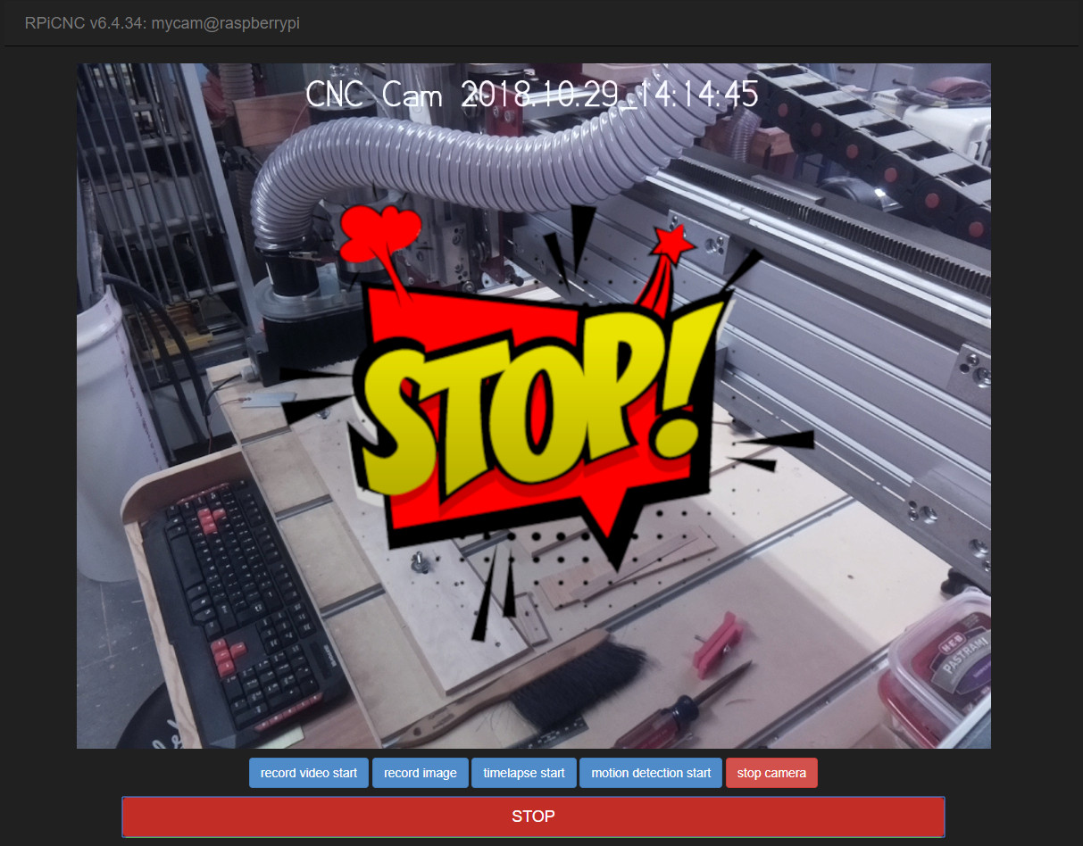

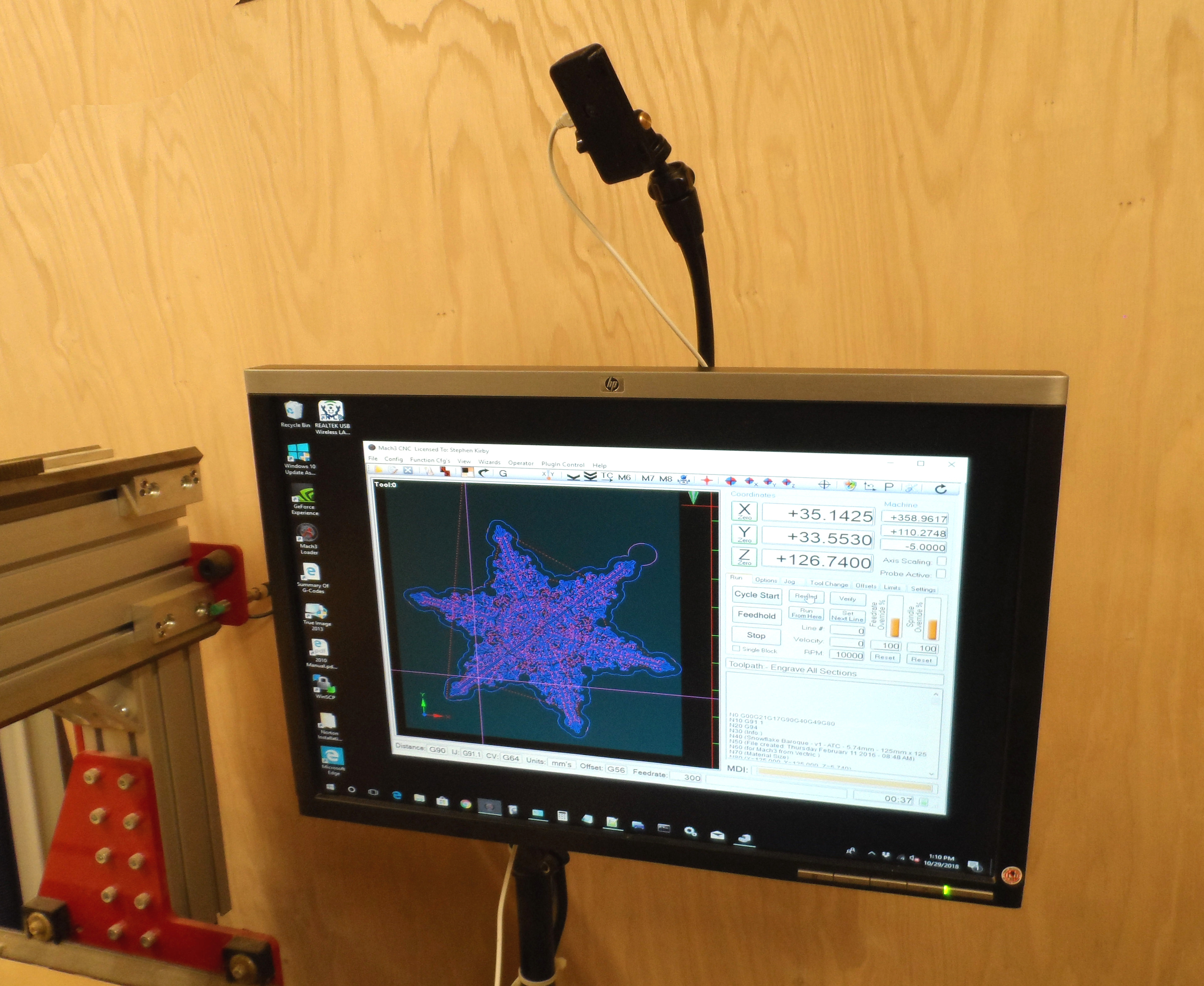
This project provides an inexpensive means of remotely performing a STOP (ALT+S) to Mach3. This is accomplished with a Raspberry Pi (RPi) + Camera connected to a PC via a USB cable. Monitoring and activating the STOP on the CNC is done with a video streaming web application running on the RPi. Using this solution should be done at your own risk. I highly recommend contacting the manufacturer of your CNC, and purchase and install the recommended remote emergency stop specified.
Note: This is not the same as an Emergency Stop (EStop) wired into your CNC control panel, but the execution of a hotkey to perform a STOP of Mach3.
Parts
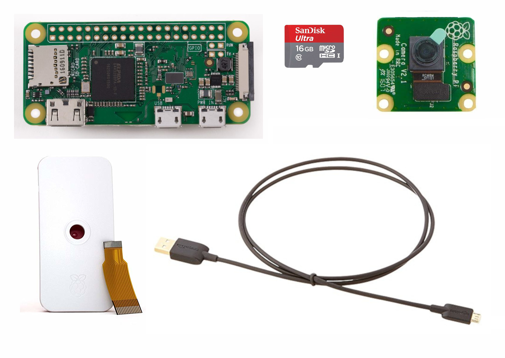
- Raspberry Pi Zero W
- Raspberry Pi Zero 1.3 Camera Cable
- Raspberry Pi Camera (Note: USB Webcams are not supported)
- Case for Raspberry Pi and Camera
- micro SD card 16 GB
- USB cable
Assemble Camera and Installing Raspbian
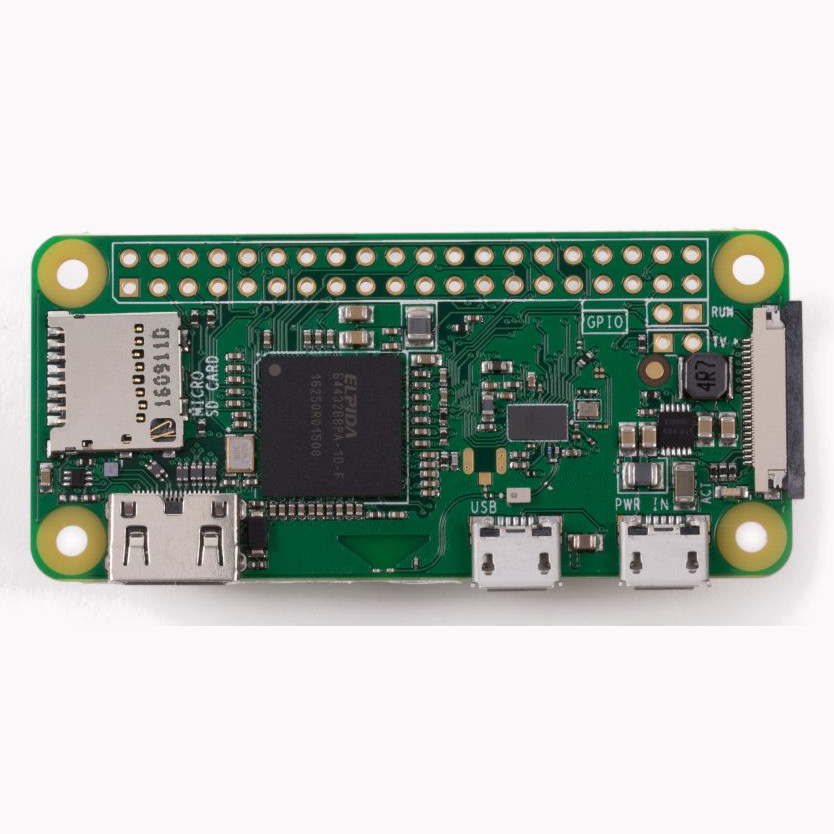
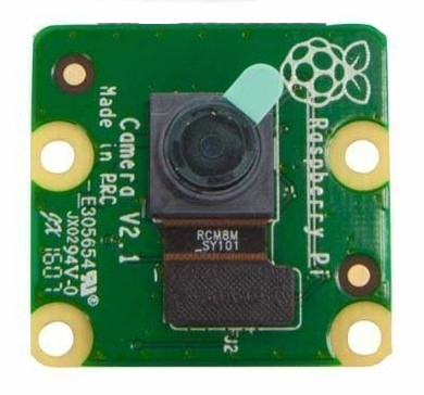
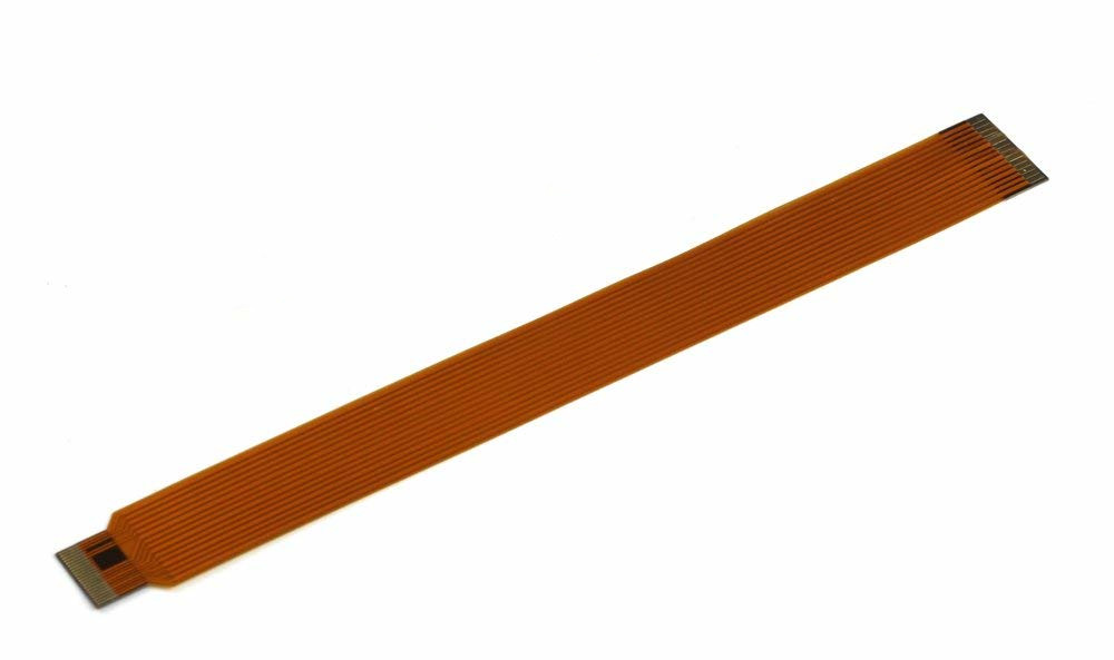
Assemble RPi Camera, cable and RPi together per instructions found at How to connect Raspberry Pi camera module to Raspberry Pi Zero W and the official case. Note: USB Webcams are not supported.
Install the latest version of Raspbian on the Raspberry Pi Zero W. I recommend following the step-by-step instructions can be found at Adafruit's Raspberry Pi Zero Headless Quick Start.
Perform an SSH connection to the RPi, as mentioned in the instructions above, and initiate a general system configuration by running the raspi-config utility.
sudo raspi-config
Enable Camera
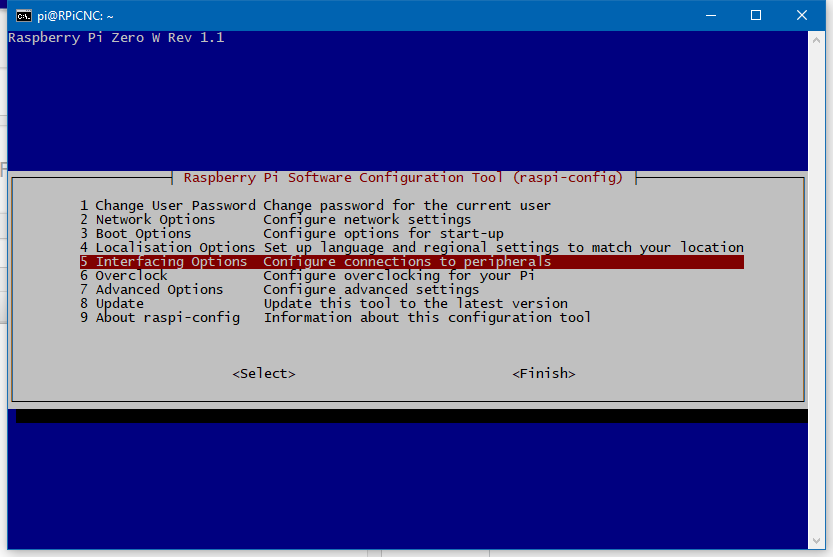
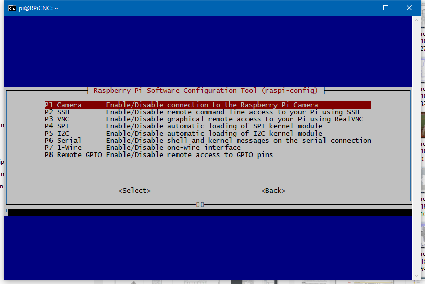
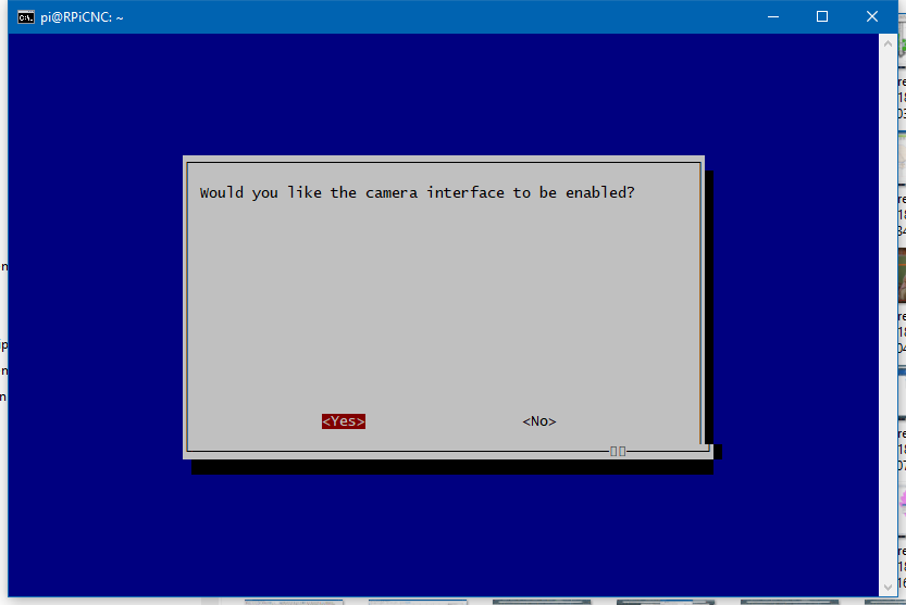
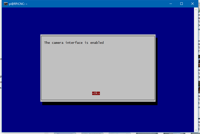
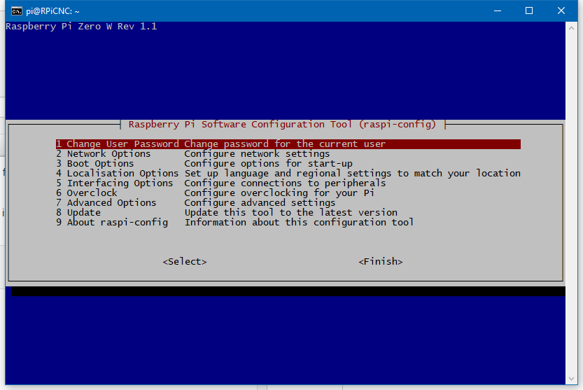
In the raspi-config main window select number 5. Interfacing Options - Configure connections to peripherals. In the next window, select P1. Camera - Enable/Disable connection to the Raspberry Pi Camera. The next window will ask Would you like the camera interface to be enabled? Select and hit Enter. The last screen will indicate that the camera interface has been enabled, and press Enter for . This will return you to the main window of raspi-config.
Expand Filesystem
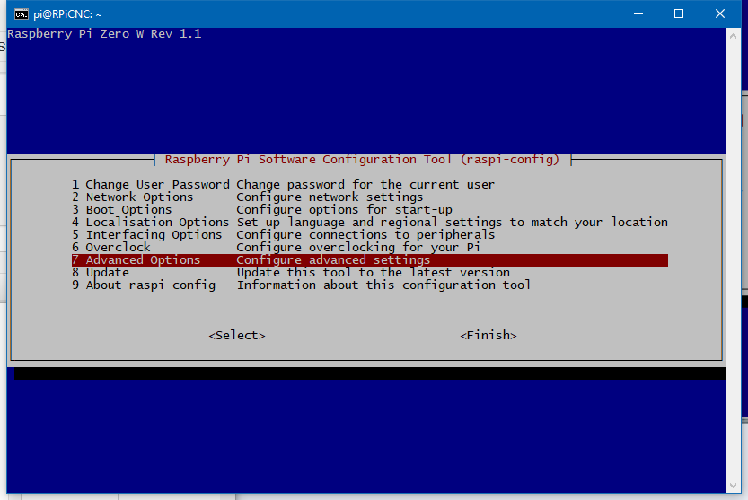
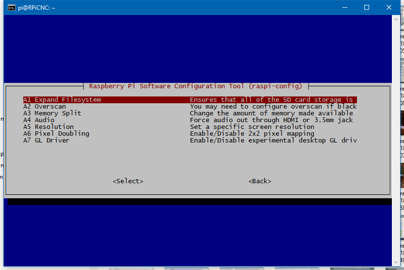
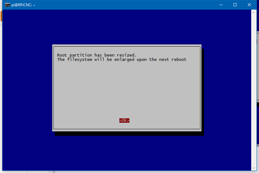
In the raspi-config main window select number 7. Advanced Options - Configure advanced settings. In the next window, select A1. Expand Filesystem - Ensures that all of the SD card storage is used. After selecting this item a window will appear indicating Root partition has been resized. The filesystem will be enlarged upon the next reboot. Hit the Enter key to select . This will return you the raspi-config main window.
Boot Options
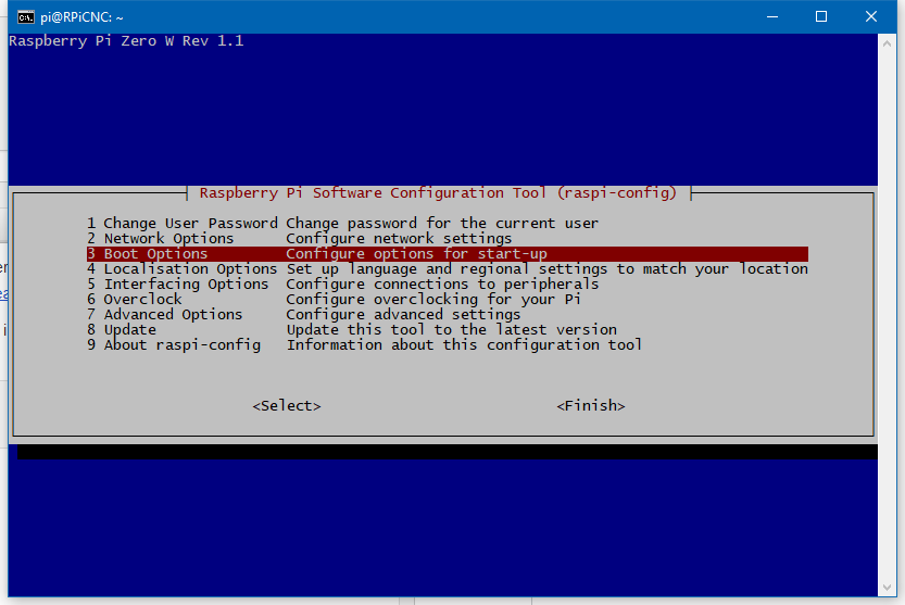
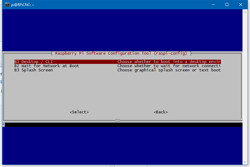
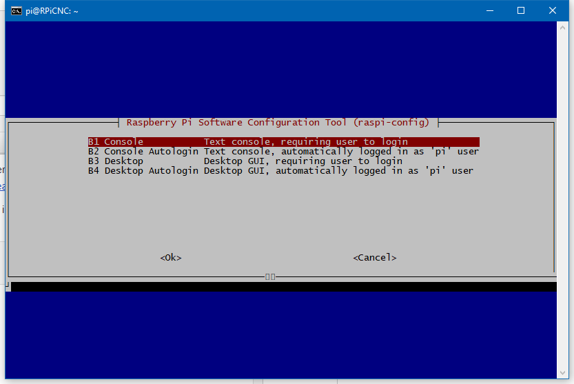
In the raspi-config main window select number 3. Boot Options - Configure options for start-up. In the next screen, select B1. Desktop / CLI - Choose whether to boot into a desktop enviroment. This will take you to the final window, and select B1. Console - Text console, requiring user to login. Selecting this will take you back to the raspi-config main window.
You can exit raspi-config by selecting , which will probably require a reboot. Execute the reboot, and SSH back into the RPi.
Configure the RPi Into USB Keyboard (HID)
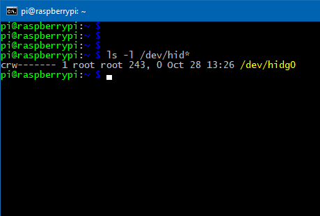
A STOP is generated by sending an ALT+s keystroke via the RPi to the PC running Mach3. As a result, the RPi needs to configured to appear and operate as USB Keyboard to the PC. This allows it to send hotkeys commands such as ALT+s to the PC. Instructions for configuring the RPi are found at Turn Raspberry Pi Zero into USB Keyboard (HID).
After a reboot, enter the following command:
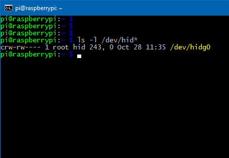
ls -l /dev/hid*
You should see the device /dev/hidg0 appearing in the list as seen above. The group access and the read and write access to this device will be altered in steps to follow.
Install RPi-Cam-Web-Interface
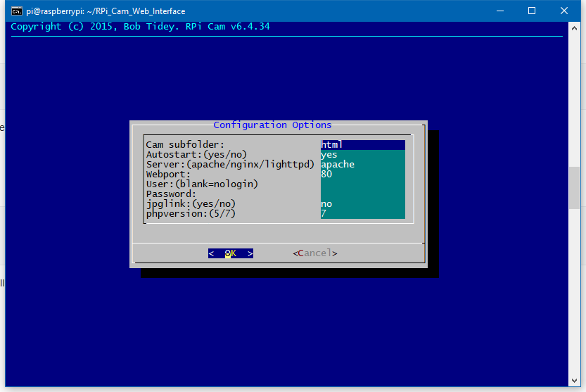
Install streaming video and web server software per instructions at RPi-Cam-Web-Interface.
During the installation you will be asked the following Configuration Options:
- Cam subfolder: html
- Autostart: (yes/no) yes
- Server: (apache/nginx/lighttpd) apache
- Webport: 80
- User: (blank=nologin) admin (example)
- Password: #34By97Zz (example)
- jpglink: (yes/no) no
- phpversion: (5/7) 7
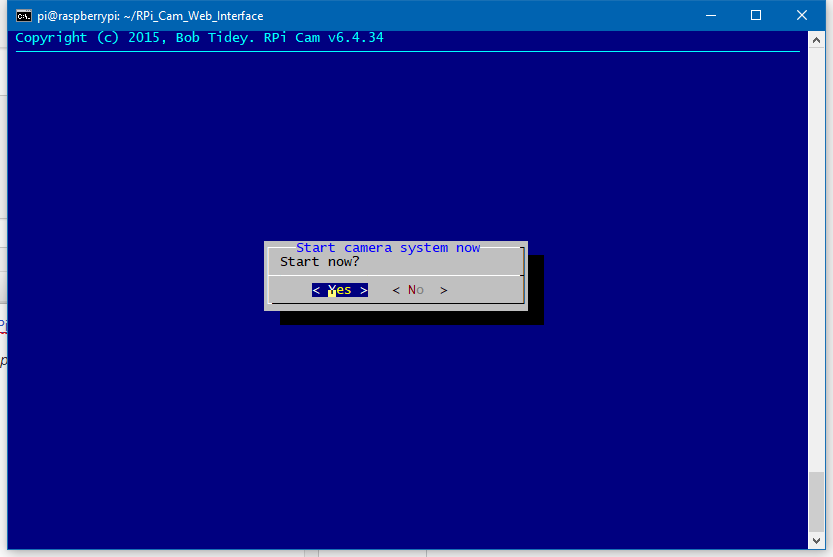
I chose the default inputs to simplify the installation, but added a User and Password to secure the RPi Web Page. Select and continue with the installation. At the end you be asked to Start Camera System Now select and continue. If successful, you will be taken to the command prompt.
Connect to RPi web page http:///html/
Grant Www-data Access to Device /dev/hidg0
Now that all of the applications and hardware have been installed the last tweaks can be done to finalize the installation. The objective in this step is to grant user www-data access to the USB Keyboard device /dev/hidg0.
First, create a group called hid and add www-data to the group:
sudo addgroup hid
sudo adduser www-data hid
Next, open /etc/rc.local with this command (again):
sudo nano /etc/rc.local
Add the following before the line containing exit 0, but below the line you added in the Configure the RPi Into USB Keyboard (HID) Step :
sudo chown root:hid /dev/hidg0
sudo chmod 660 /dev/hidg0
The above command will provide the necessary access to device /dev/hidg0 for user www-data. After the above modifications have been made and a reboot you see the /dev/hidg0 device with following command:
ls -l /dev/hid*
Notice the group for this device is now hid and the group has read and write access.
======================================
Optional: If you wish to use scripts that access GPIO, I2C and/or SPI via the RPi Web page, you will need to enable these interfaces in raspi-config. Secondly, you will need to grant user www-data access to these interfaces.
sudo usermod -a -G gpio,i2c,spi www-data
Configure the Web Interface
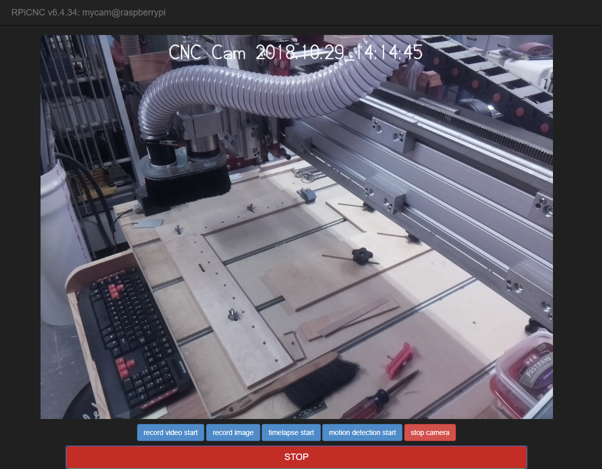
Upload the userbuttons.txt file found below to your RPi home directory '/home/pi/'.
From your home directory, copy userbuttons.txt to folder '/var/www/html/':
cd ~
sudo cp userbuttons.txt /var/www/html/userbutton
Change ownership and permissions for userbuttons:
sudo chown www-data:www-data /var/www/html/userbutton
Create the stop_cnc.sh shell script:
sudo nano /var/www/html/macros/stop_cnc.sh
Copy and paste the following text to this file:
#!/bin/bash
function write_report {
     echo -ne $1 > /dev/hidg0
}
# CTRL=x10 SHIFT=x20 ALT=x40
# ALT + s
write_report "\x40\0\x16\0\0\0\0\0"
# Null
write_report "\0\0\0\0\0\0\0\0"

#echo "STOP CNC" >> /var/www/html/macros/testmacro.txt
After saving /var/www/html/macros/stop_cnc.sh, provide the necessary permissions to the file with these commands:
sudo chown www-data:www-data /var/www/html/macros/stop_cnc.sh
sudo chmod 764 /var/www/html/macros/stop_cnc.sh
======================================
Optional: If you wish to have buttons for CYCLE START and FEED HOLD, you can add the following buttons to /var/www/html/userbuttons:
sudo nano /var/www/html/userbuttons
Find and remove the # from the lines shown below in the userbuttons file:
#FEED HOLD,feed_hold.sh,btn btn-warning btn-lg,style="width:50%"
#CYCLE START,cycle_start.sh,btn btn-success btn-lg,style="width:50%"
Create the cycle_start.sh shell script:
sudo nano /var/www/html/macros/cycle_start.sh
Copy and paste the following text to this file:
#!/bin/bash
function write_report {
	echo -ne $1 > /dev/hidg0
}
# CTRL=x10 SHIFT=x20 ALT=x40
# ALT + r - CYCLE START
write_report "\x40\0\x15\0\0\0\0\0"
# Null
write_report "\0\0\0\0\0\0\0\0"
#echo "CYCLE START" >> /var/www/html/macros/cycle_start.txt
Create the feed_hold.sh shell script:
sudo nano /var/www/html/macros/feed_hold.sh
Copy and paste the following text to this file:
#!/bin/bash
function write_report {
	echo -ne $1 > /dev/hidg0
}
# CTRL=x10 SHIFT=x20 ALT=x40
# SPACE - FEED HOLD
write_report "\0\0\x2c\0\0\0\0\0"
# Null
write_report "\0\0\0\0\0\0\0\0"

#echo "FEED HOLD" >> /var/www/html/macros/feed_hold.txt
Change ownership and permissions of shell scripts:
sudo chown www-data:www-data /var/www/html/macros/cycle_start.sh
sudo chown www-data:www-data /var/www/html/macros/feed_hold.sh
sudo chmod 764 /var/www/html/macros/cycle_start.sh
sudo chmod 764 /var/www/html/macros/feed_hold.sh
Downloads
Customize the Web Appearance
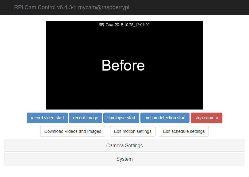
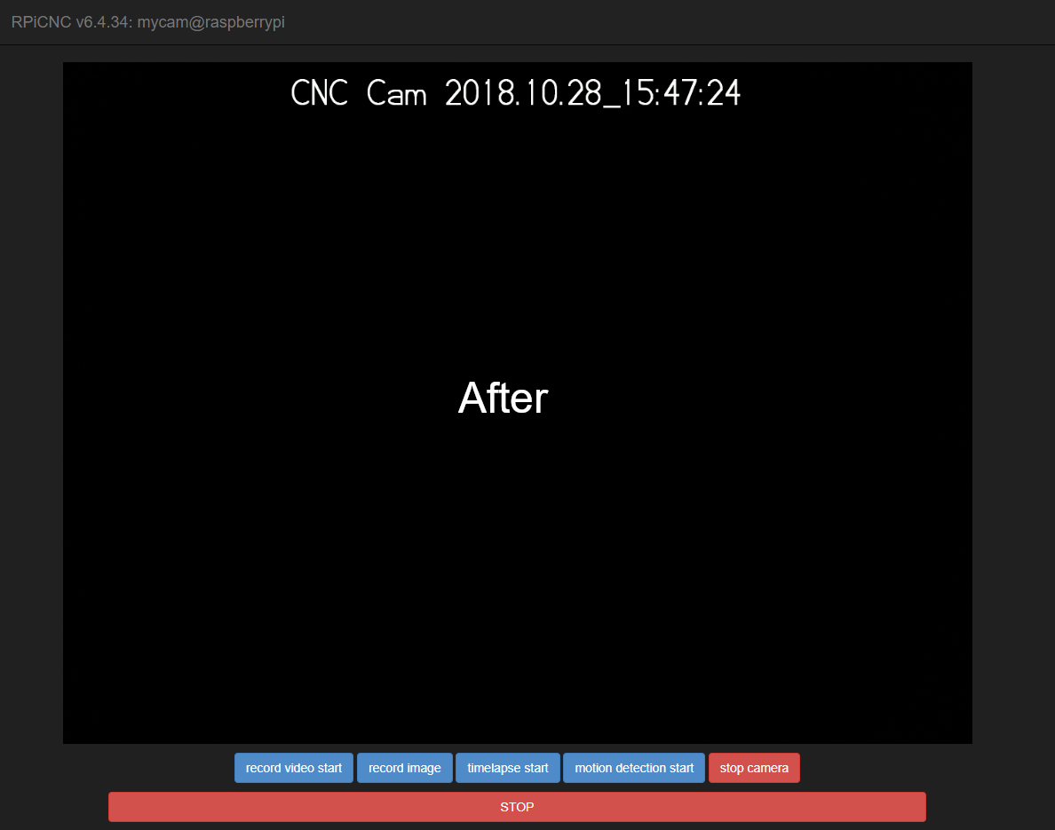
Prior to the previous step, the Web page appeared as the 'Before' image shown above. After the modifications in the STOP button will appear. Some of the recommended changes in the Camera Settings:
- Resolutions: Max View 972p 4:3
-
Annotation (max 127 characters): Text: CNC Cam %Y.%M.%D_%h:%m:%s
- Preview quality (1...100) Default 10: 50
Width (128...1024) Default 512: 1024
Divider (1-16) Default 1: 1
The title bar name and name 'RPi Cam Control v6.4.34: mycam@raspberrypi' may be modified by customizing the /var/www/html/config.php file.
sudo nano /var/www/html/config.php
Modify 'RPi Cam Control' if you wish to change the Title name:
// name of this application
define('APP_NAME', 'RPi Cam Control');
In the 'System' settings section you can change the Style to Night and click OK to turn the background black.
Testing and Using
Connect a USB cable to the USB port of the RPi (not the PWR USB), and connect the other end to the PC running Mach3. This cable will power the RPi as well as control Mach3 on the PC. Therefore, DO NOT connect an external power supply to PWR USB on the RPi. This might cause damage to the PC or RPi.
focus - The window that currently has keyboard focus. Any keystrokes from the keyboard will occur in this window.
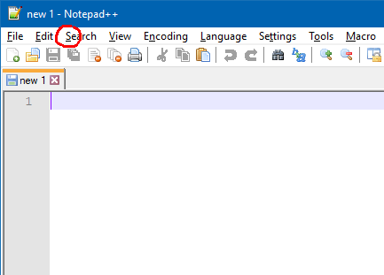
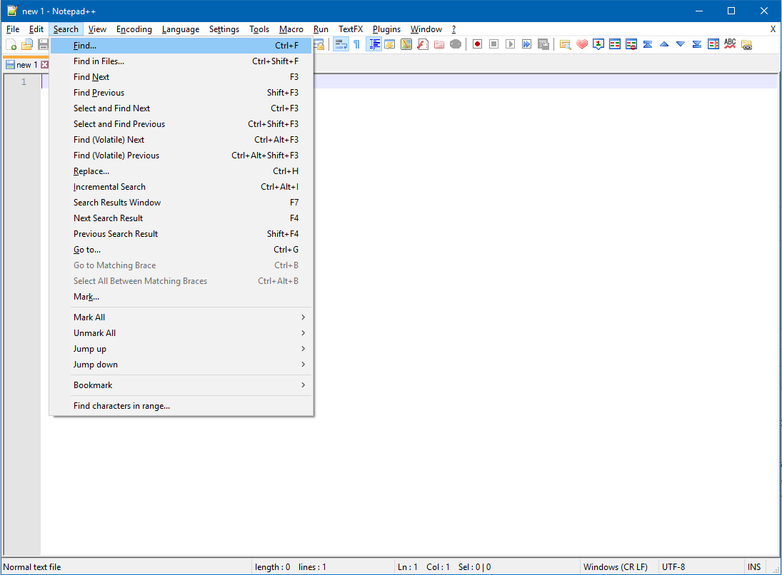
As mentioned previously, the RPi's USB sends an ALT+s hotkey to the USB of the attached PC. In order to test the setup (without Mach3), open an application (preferably a text editor) that has a Menu option that begins with S, as seen above in the Notepad++ application. Notice that the S is underlined in the Menu indicating that an ALT+s keystroke will activate the menu. You can try it with the PCs keyboard to test the results. As in the example above, the Search menu appeared. Your results will be different, depending on the application you open with a Menu containing an option with S. If your test was successful, test your setup with the Web application. Set the focus on the same application as before, and access the Web application of the RPi from a different device. You can even use a smart phone to access the RPi. Click the STOP button on the Web page, and the same Menu should drop down as before.
If your test are successful, you're ready to use this with Mach3. I use Mach3 2010 Screenset, and it works fine.
Make sure that Mach3 is in focus for the PCs keyboard input. Touching the title bar of Mach3 is sufficient enough to insure this is the case. Mach3 should be the only application running on the Desktop of the PC.
Using this method should be done at your own risk.