Ball Bearing Baren for Lino-Cut Relief Printing With Fusion 360 Updated 21.10.2021
4044 Views, 30 Favorites, 0 Comments
Ball Bearing Baren for Lino-Cut Relief Printing With Fusion 360 Updated 21.10.2021
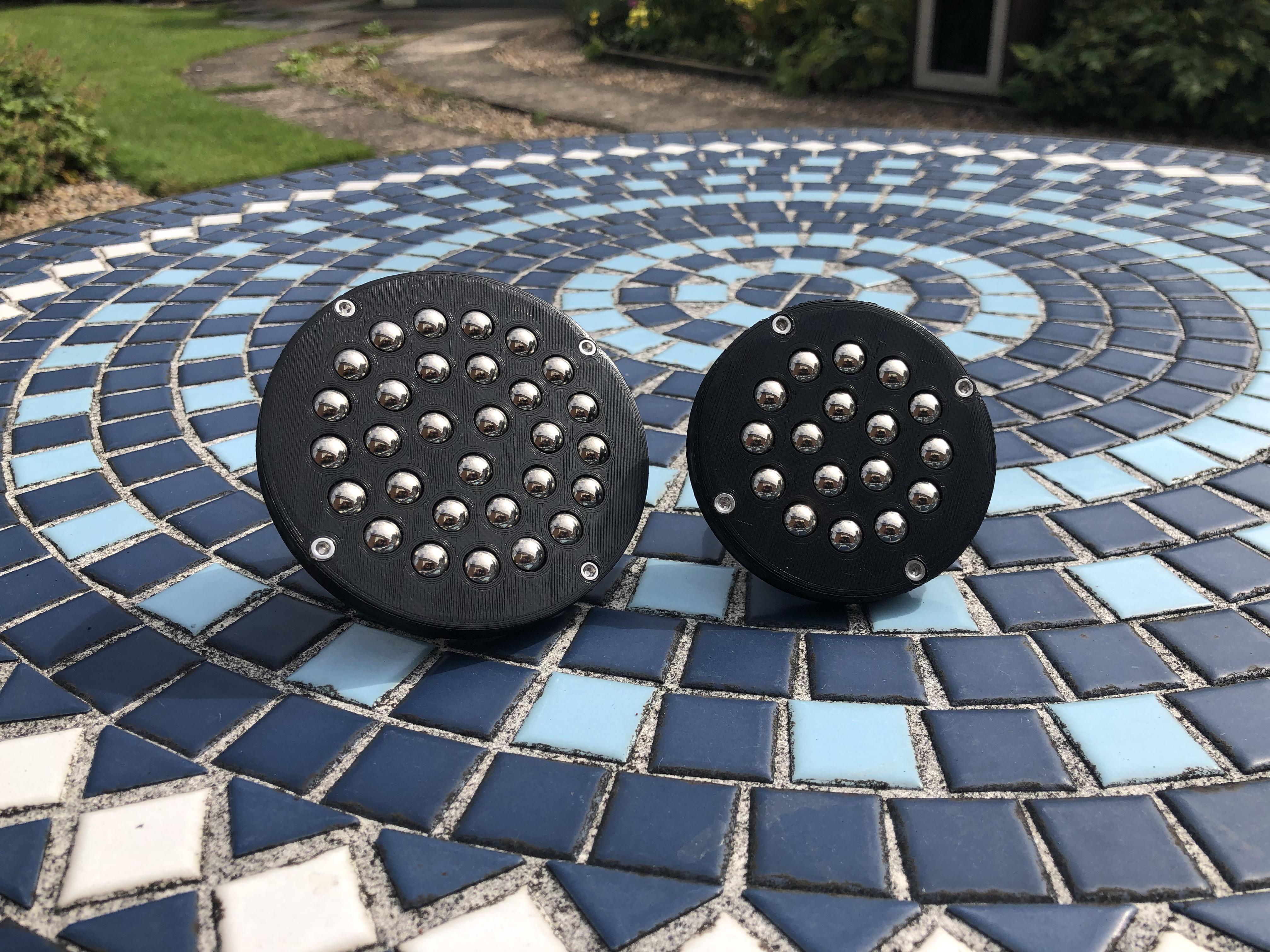
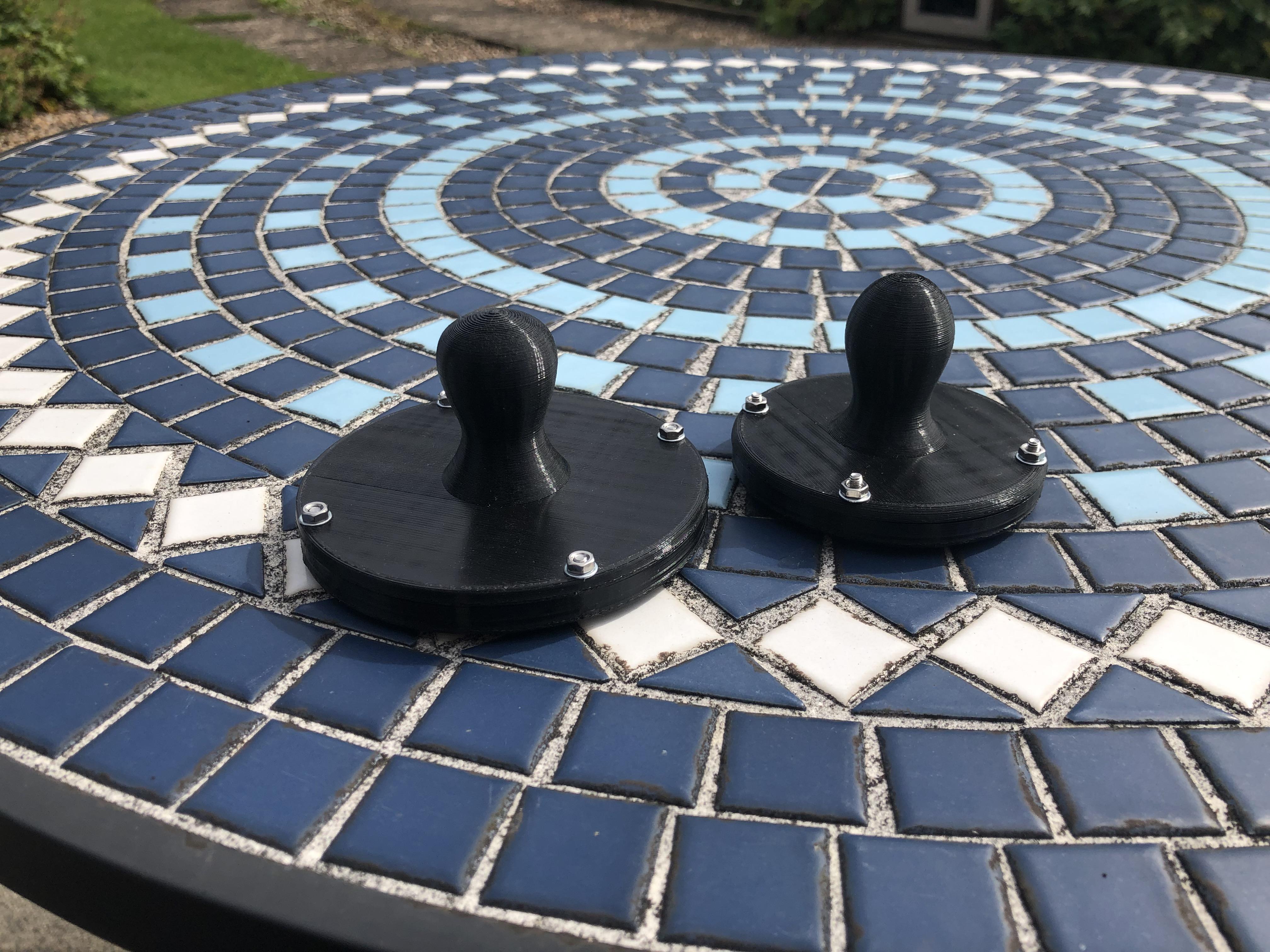
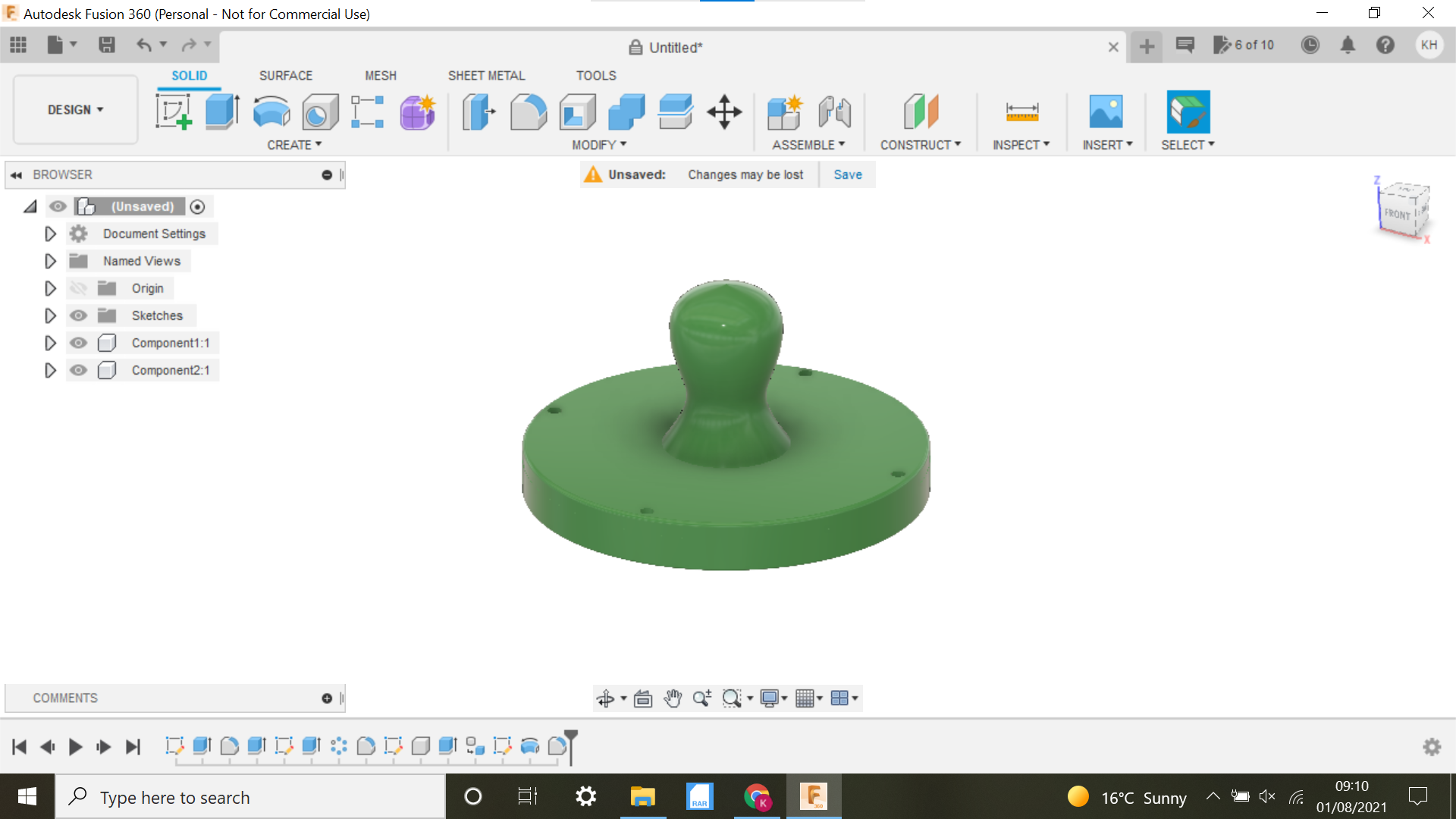
In this Instructable I will show you how I made a Fusion 360 designed 3D Printed Ball Bearing Baren.
My friends daughter asked me if there was any chance of me making a Ball Bearing Baren for Relief Printing, my first responses were what on earth is a Ball Bearing Baren?? and what is relief printing?? so I had a look online and was surprised at how much they were to buy, these things run up to $400, £259 here in the UK.
There was a 3D printed version online but I thought, that's too easy, lets make our own design using Fusion 360 the only stumbling blocks I could see initially was how to contain the balls within the base and the height of the base, so the ball bearings could move freely.
Within Fusion 360 we will be using the Circular pattern function for creating the array of circles, and revolve when we come to design the handle.
Onto the design.
Updated 21.10.2021 New Video Added.
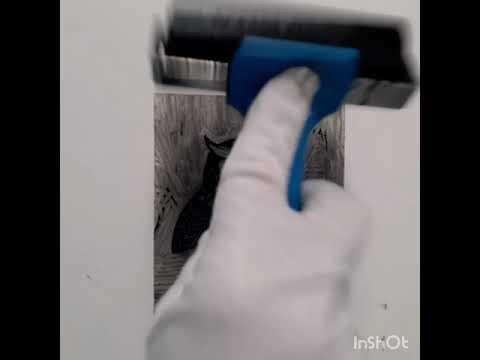
A video of a friend of mine using a Prototype Baren, my friend suggested I might make one with a larger area and smaller ball bearings, this prototype has 6mm Ball Bearings and as you can see in the Video it works very well.
Supplies
Fusion 360
3D Printer
1.75 PLA
9.5mm Ball Bearings(That's the only size I had)
3mm Allen head Bolts, Nuts and Washers
Beeswax
Designing the Ball Bearing Baren Base
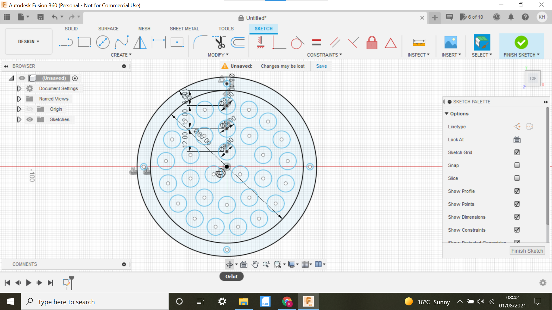
My first thoughts were to go full steam ahead and try to design and 3D print a full size Baren, they look to be around 100-120mm but then my sensible side kicked in(Light bulb Moment) why not start off with a smaller one, we will probably need a couple of prototypes to get it right, this turned out to be true.
The size I selected to start off with was 80mm bearing in mind that the ball bearings were 9.5mm.
Once we had a design that worked any size could be chosen and different size ball bearings could be used.
To the sketch:
Open Fusion 360 and select new component and the create sketch selecting the top plane.
Create a Centre Circle @ 80mm and then offset by 7mm this outer band is where we will place the holes for the Allen bolts.
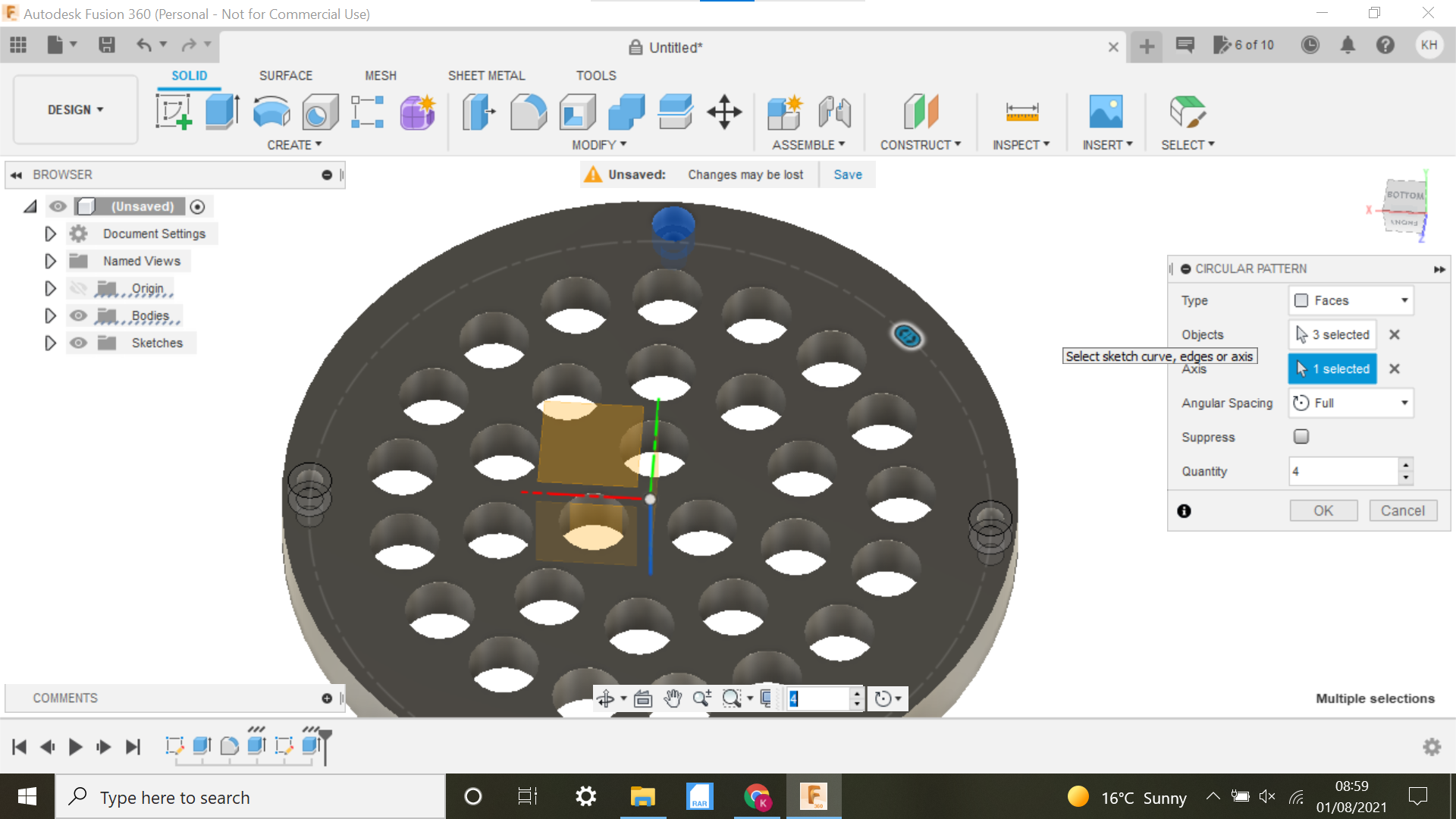
Draw a line from the top of the circle to the top of the inner circle, this will give us a centre point for a 3.4mm centre circle for the allen bolts, we then select the Circular pattern tab in the drop down box, Highlight the 3.4mm circle and then click on the axis tab and select the centre of the main circle, I opted for 4 fixing points.
For the first ball bearing circle, I took a dimension of 8mm from the top of the inner circle and then created a centre circle of 9mm, using the circular pattern tab again I created an array of 17 circles using the centre of the main circle for the centre point, measure 12mm between centres for the next circle and created 10 circles, leaving us with 3 in the middle of the sketch, no hard and fast rules here, if it looks as if there is enough space between the circles it will be just fine.
With the circles for both the fasteners and the ball bearings now created, we can move onto extruding the sketch:
The First Extrusion, Fillet
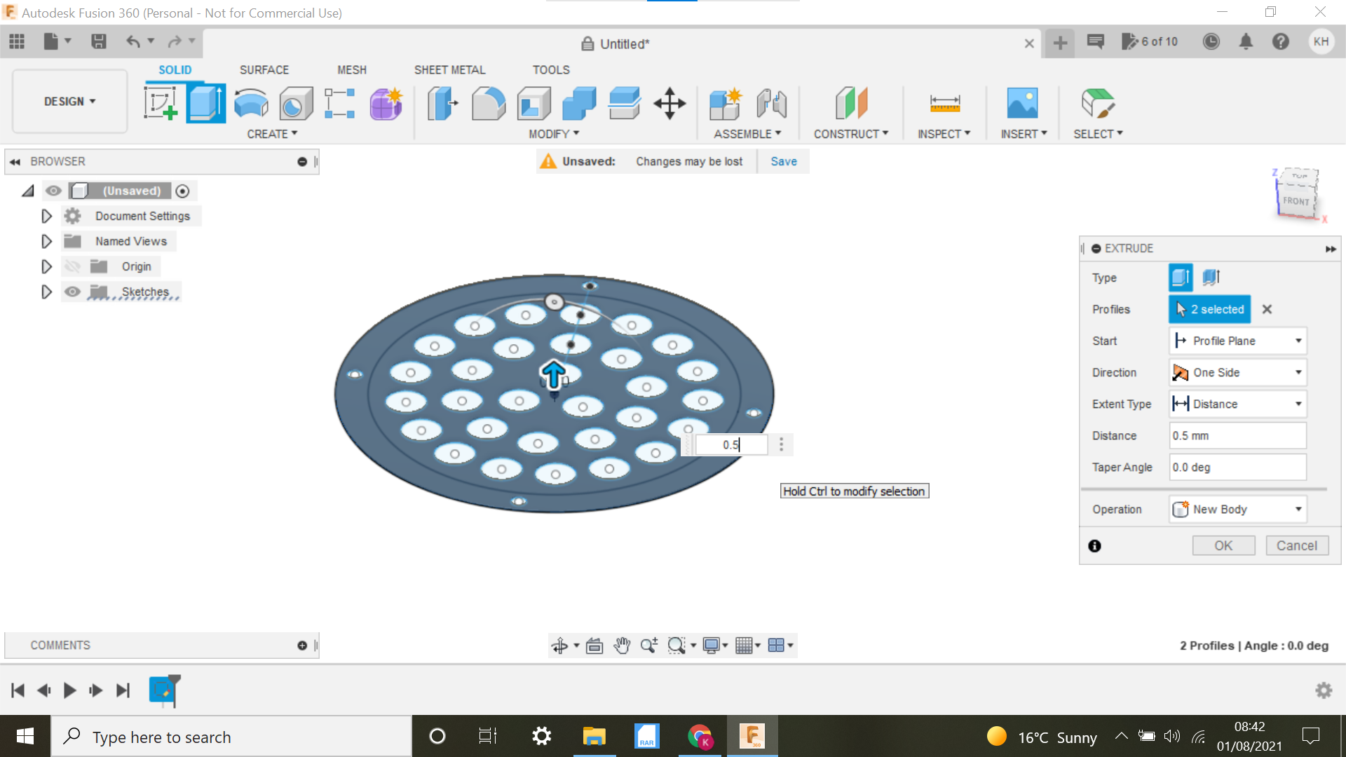
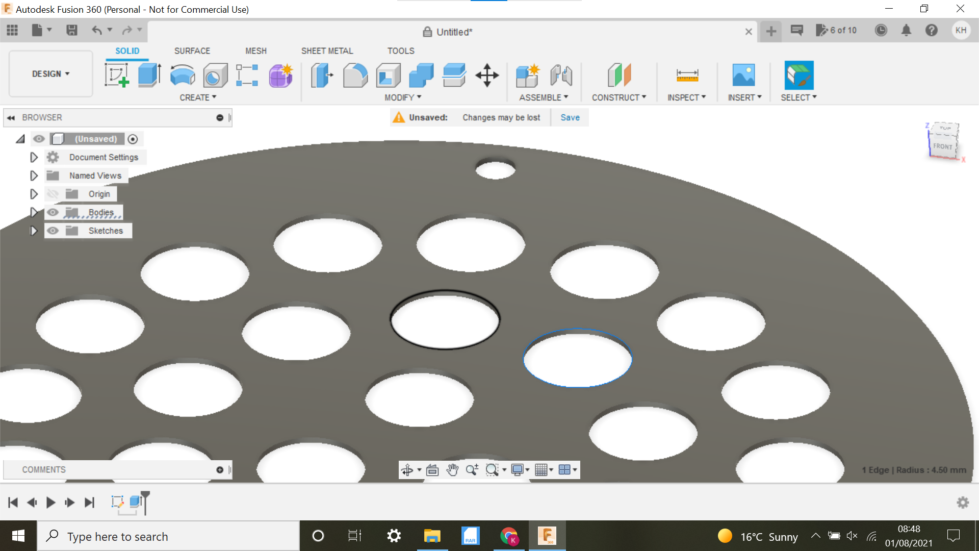
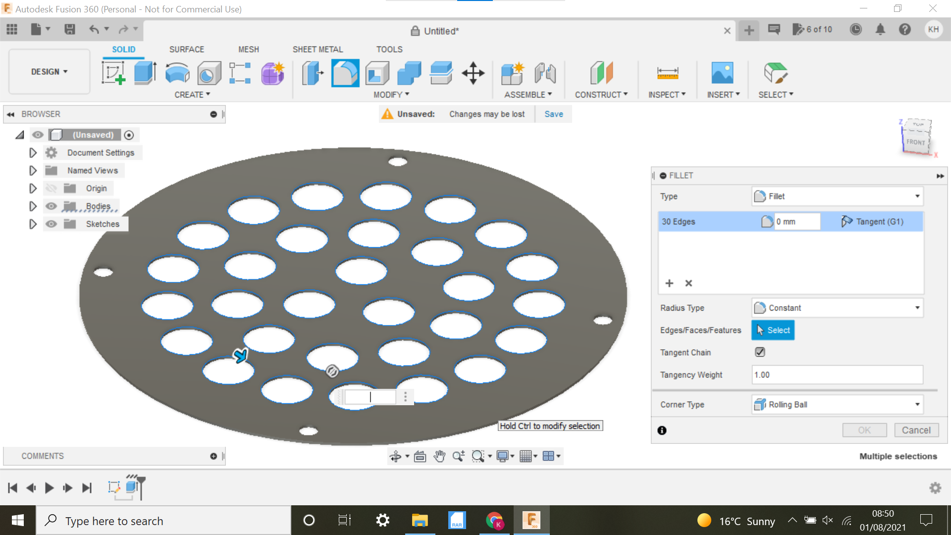
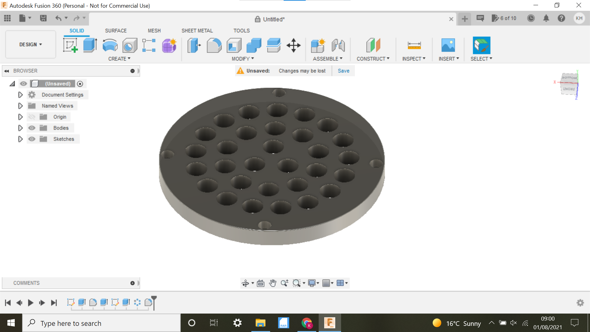
Remember we made the circles for the ball bearings 9mm when the ball bearings are 9.5mm? this is because we need to create a fillet to contain the balls, each circle has to be highlighted and a fillet of 0.75 is made, (ensure you click on the top of the circle not the bottom), I found out when doing it this way, when extruding to the full depth, it worked out really well giving the ball bearings enough room to move freely within the holes.
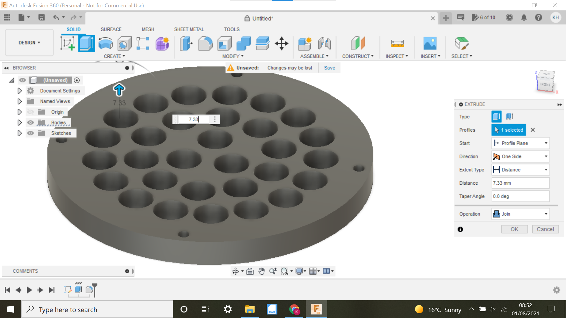
We now select the top surface and extrude to a further 7.33mm this added to the initial 0.5mm gives just enough clearance for the ball bearings to move freely when the Top of the Baren is fitted and bolted together, not forgetting that the ball bearing is protruding through the hole, again this was trial and error initially.
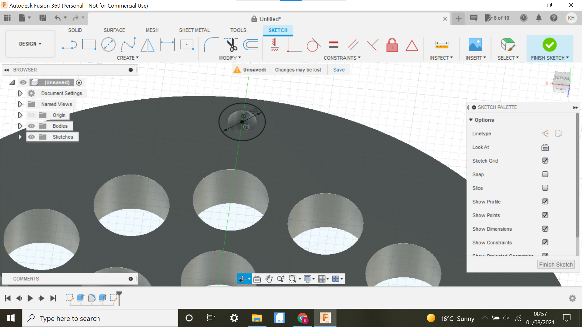
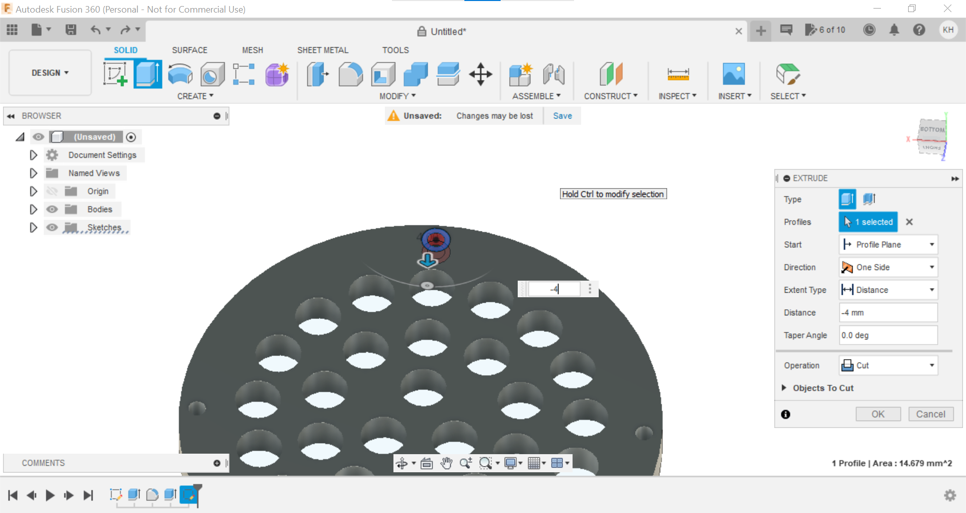
We now flip the base over, and select the bottom face to create our sketch, create a centre circle of 5.5mm on one of the outer 3.4mm holes, then extrude to -4mm this will be plenty to sink the Allen bolt into the base, then using Circular pattern select the faces of the newly extruded hole, and select the blue line of the origin I think this would be the Z but don't quote me on that, this now gives us the 4 holes to sink the Allen head bolts into.
I added a 0.5mm fillet to the bottom edge just to finish off.
Onto the Top of the Baren or the handle:
The Handle Part of the Baren.
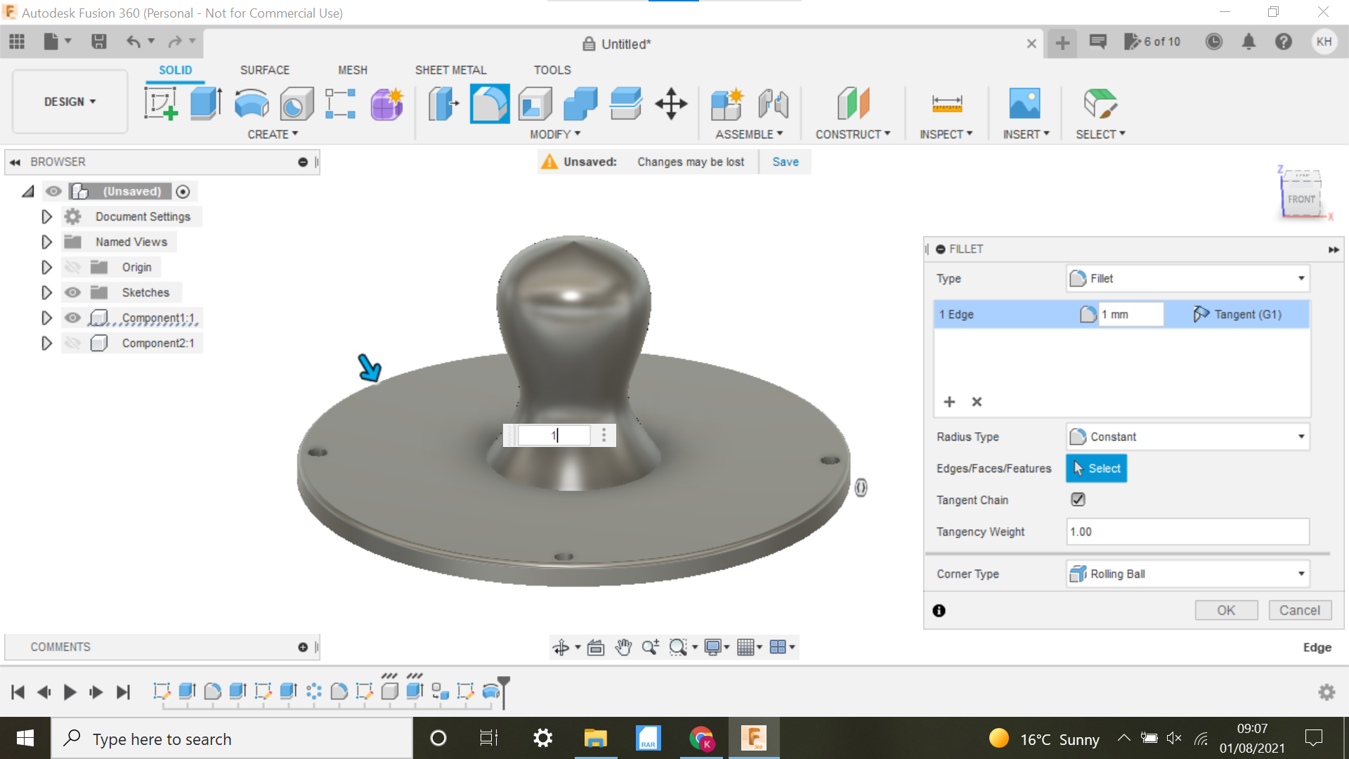
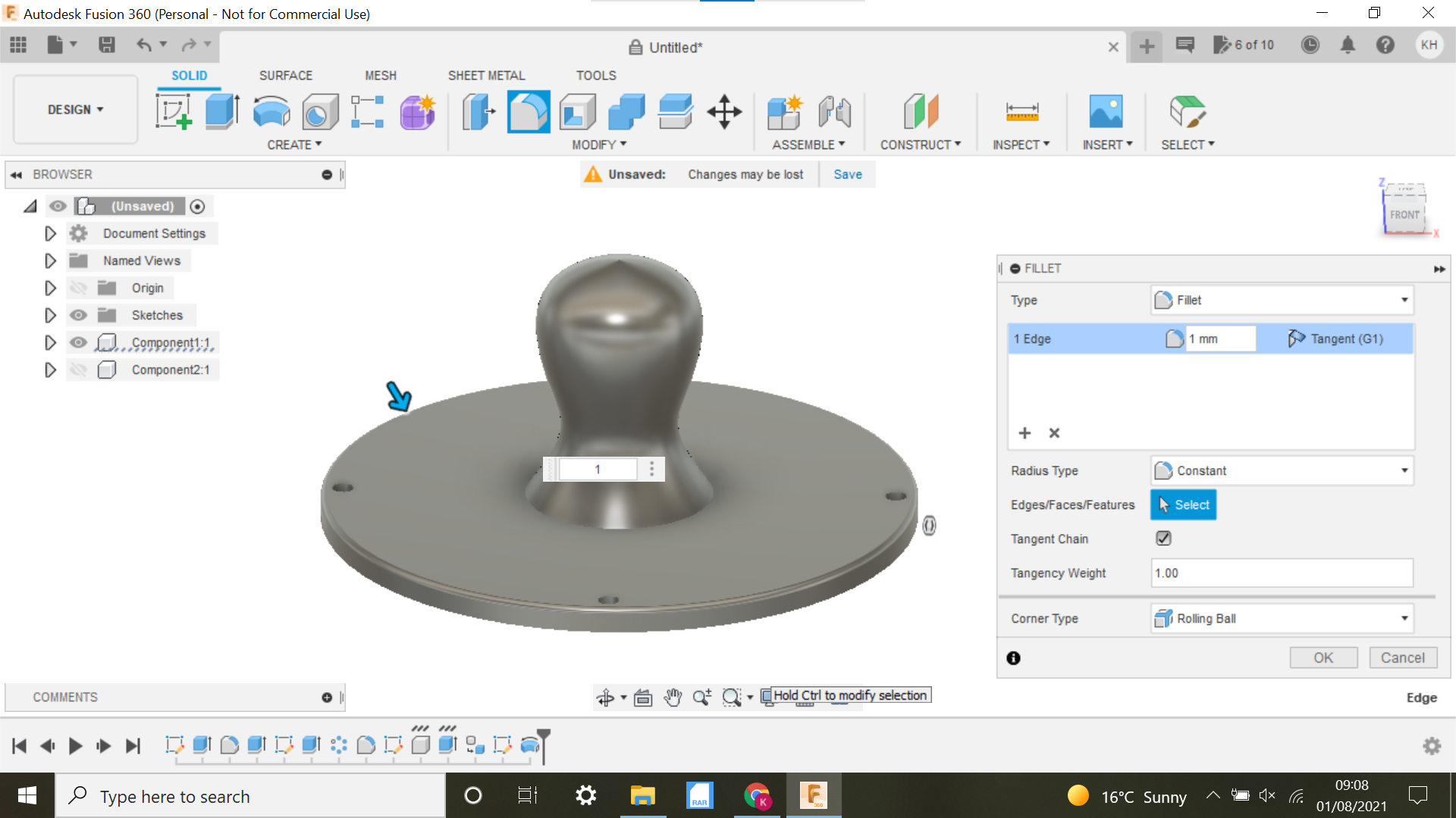
Don't forget to flip the design back, we need to work from the Top face now.
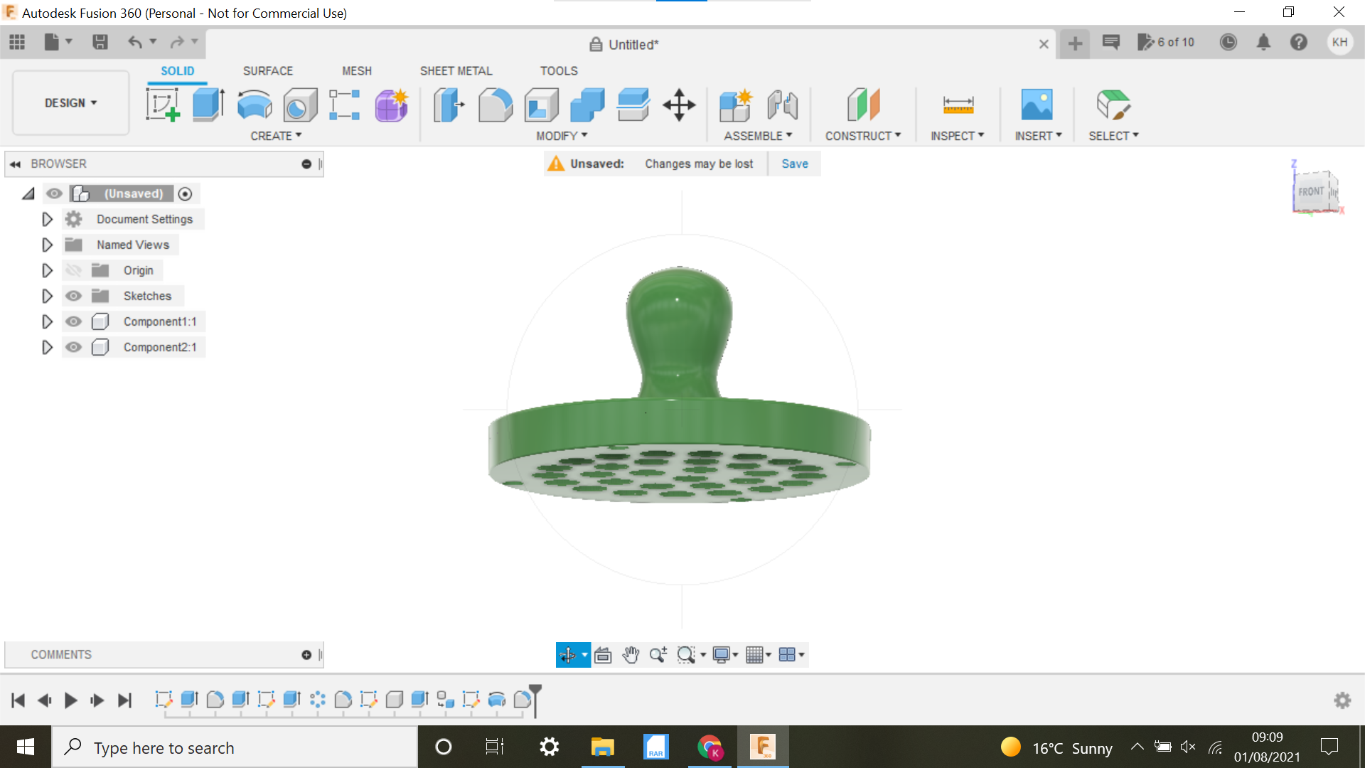
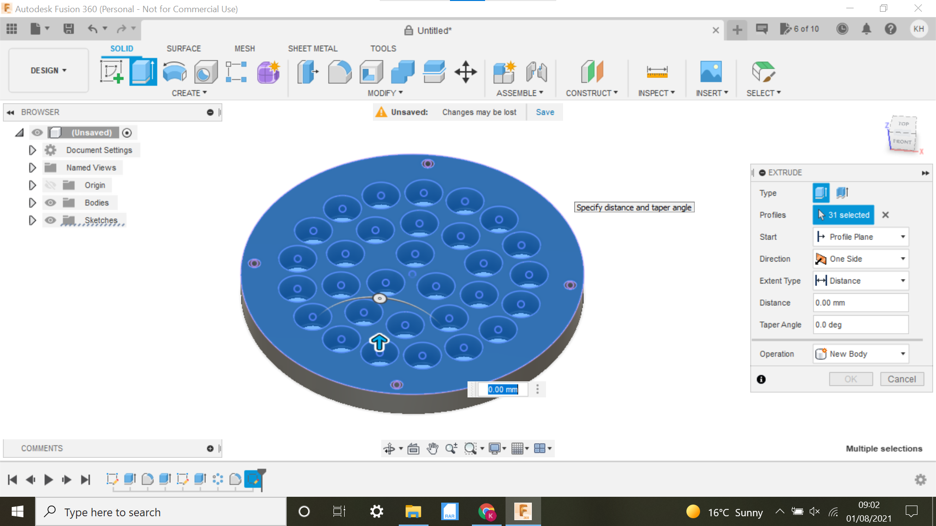
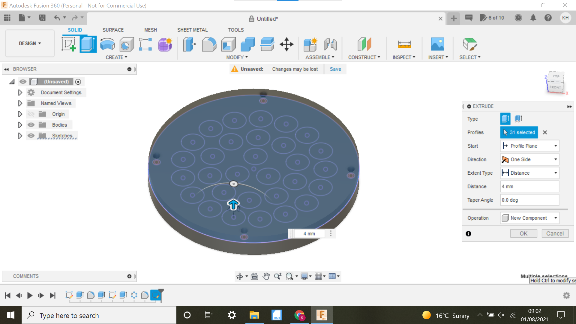
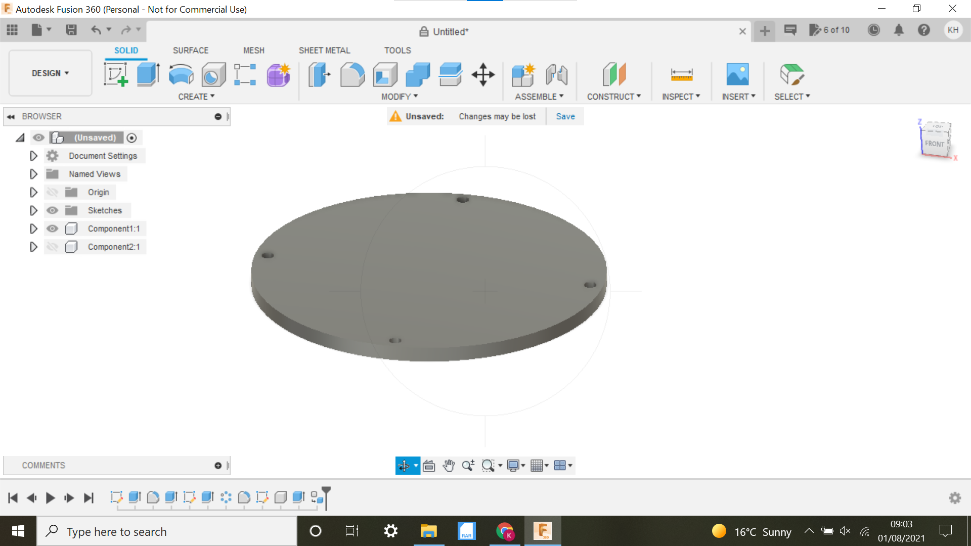
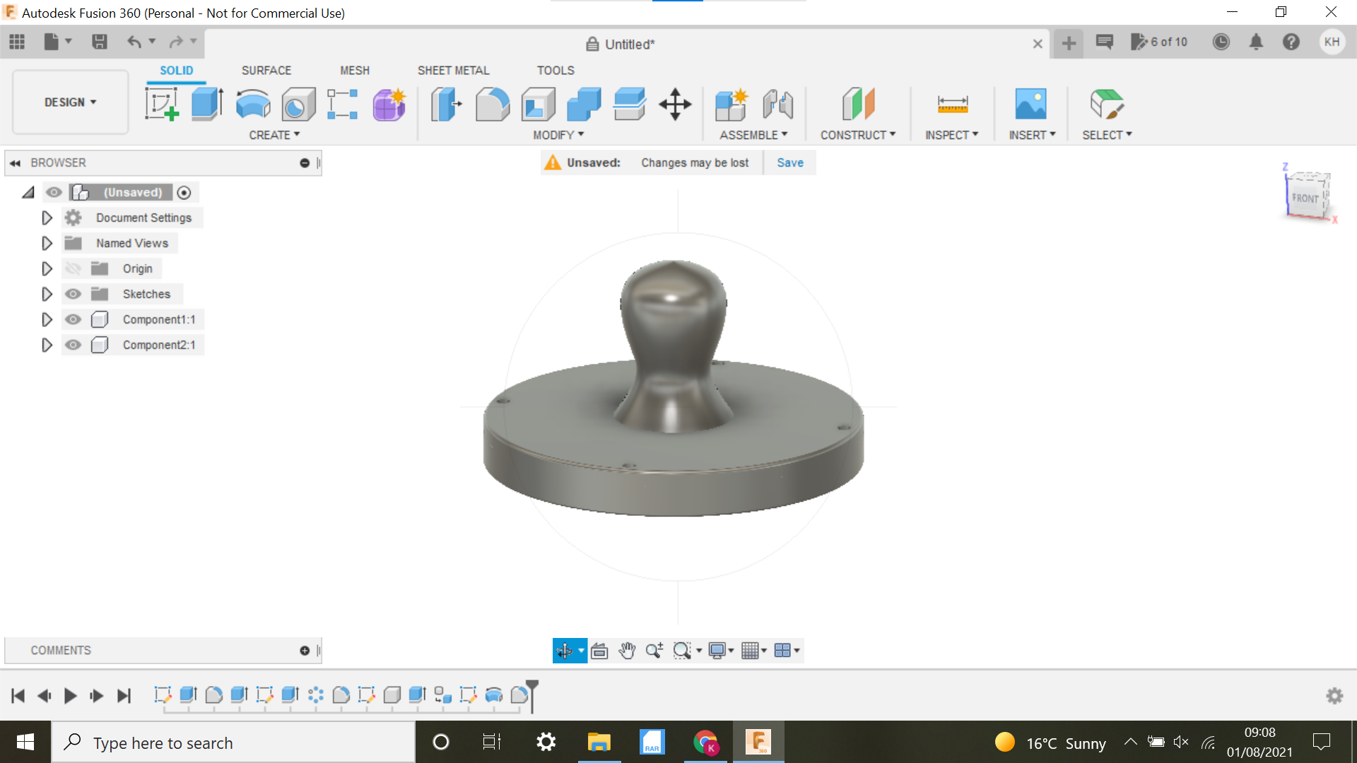
Create a new sketch and select the top face of the base of the Baren, we now need to project this so we can extrude it as a new component, press P on the keyboard for Project and select the top of the base, click ok, all the holes apart from the holes for the fasteners will have to be highlighted as well, then using extrude, extrude to 4mm make sure you select new component in the drop down box as in the screen shot.
Cool create a component from the first body, we now have 2 components to work with.
We can now turn off the first component, the base, as we are finished with that until we come to print it.
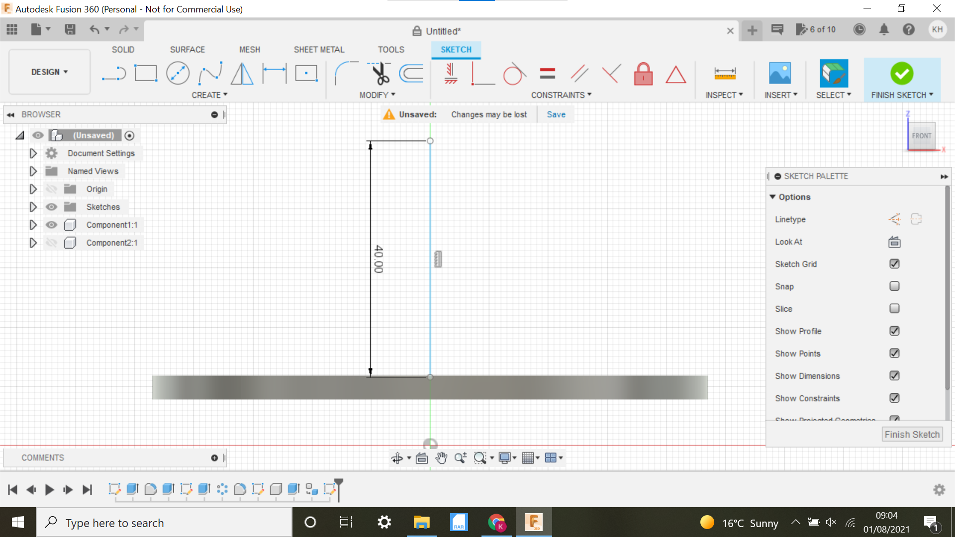
We now need to create a handle for the Baren, this could be any design you want really, I will use the centre plane and create a sketch and then use the Revolve function to form the handle.
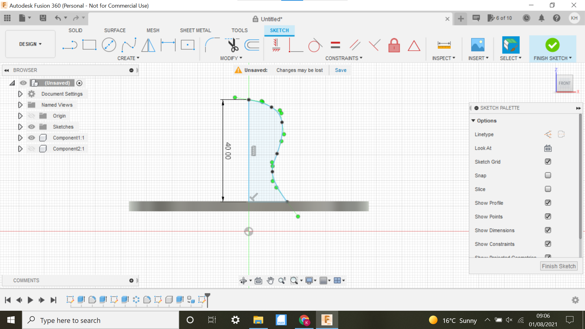
Create sketch selecting the centre plane, then sketch a line from the centre vertically to say 40mm, sink the line into the Top plate 1mm or so, then selecting the spline tool, create half of what looks like what could be a comfortable grip handle, tweak the pointers to manipulate if necessary then join the 2 points at the bottom with a connecting line, the sketch will turn light blue.
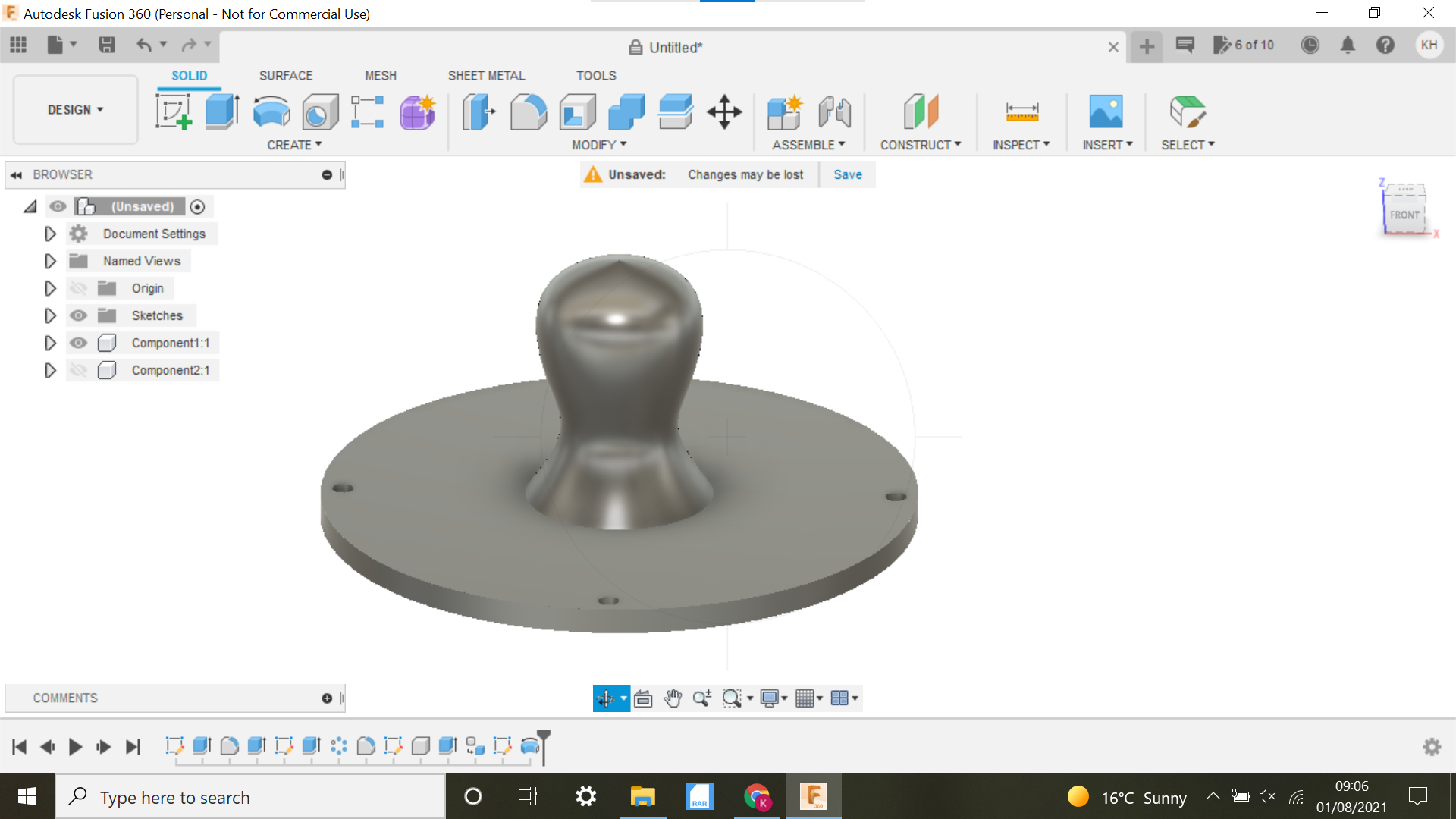
In the solid section, select Revolve, it will automatically highlight the sketch, and select the vertical line as the Axis, Voila we have a handle, ensure to select Join in the drop down box, I will use the combine function just to be sure that it is one component, selecting both the handle and top plate and Join, click ok.
3D Printing the Baren
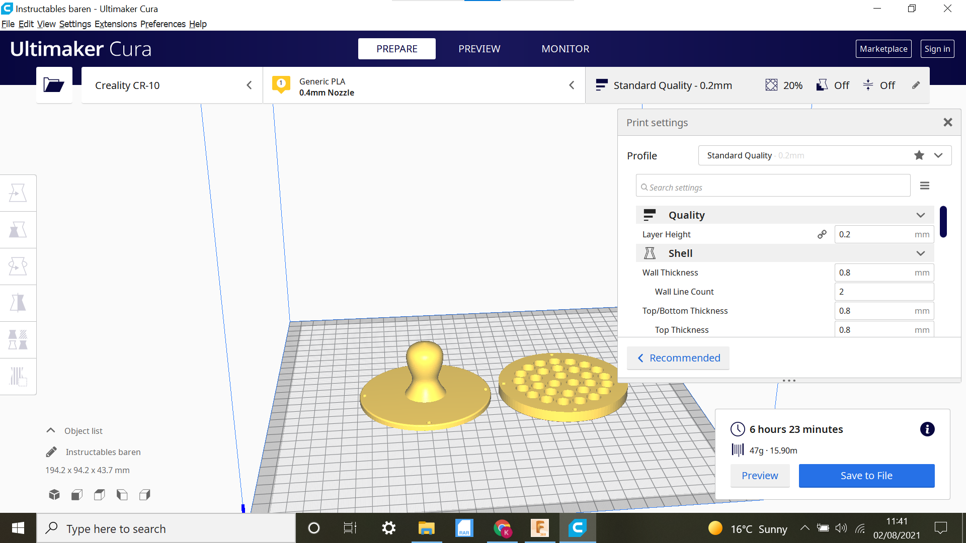
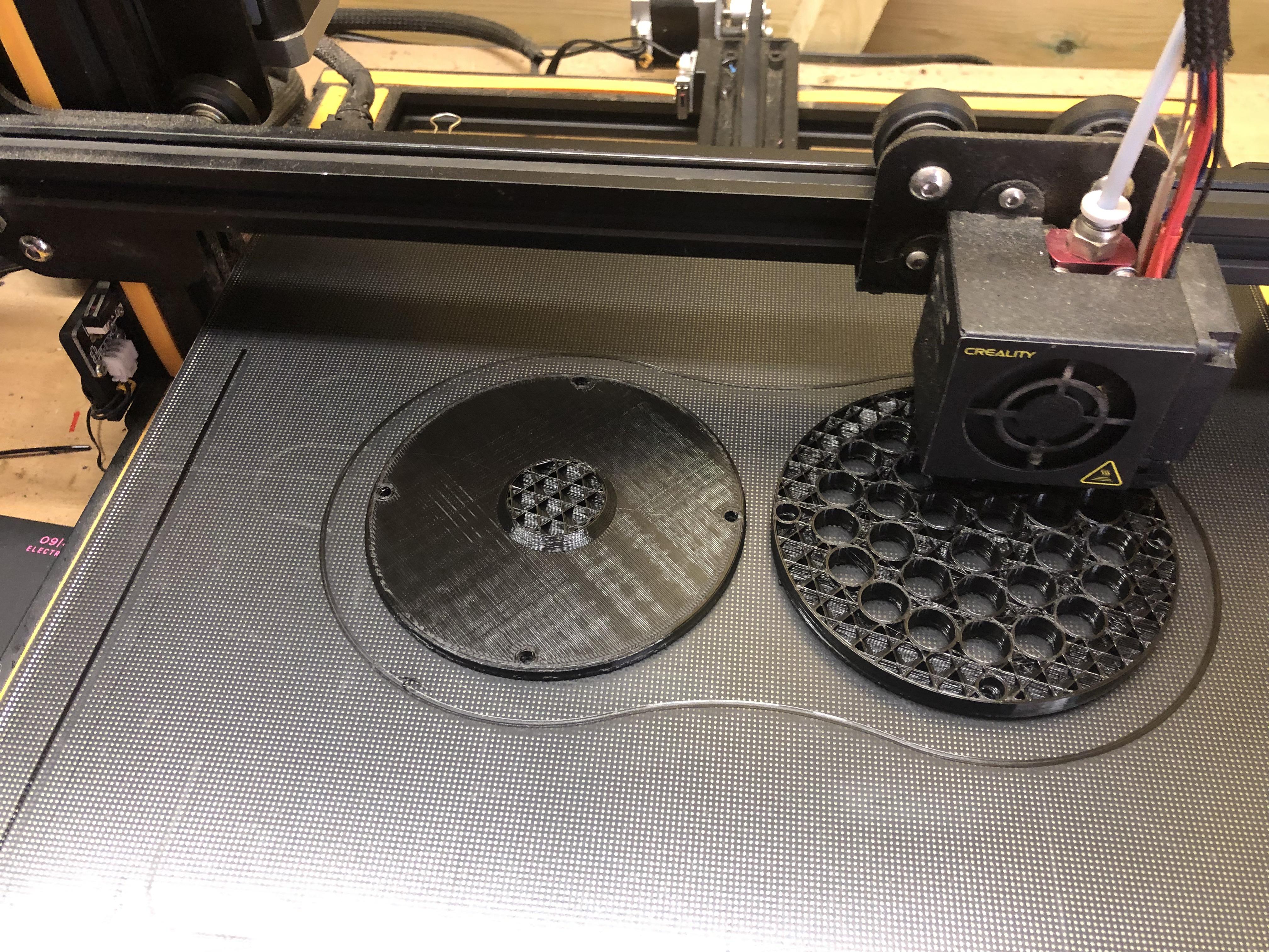
No fancy print settings or anything, I just selected medium refinement in Fusion 360 and orientation on the print bed was as they are in Fusion 360.
I tried printing the base the other way round as the 3mm holes were a bit tight when printed face down, but it messed with the ball bearing holes, no supports, my heat settings with PLA are 210 nozzle and 65 for the bed this works for me using the Creality glass plate, and leave to go cold.
Completing the Baren
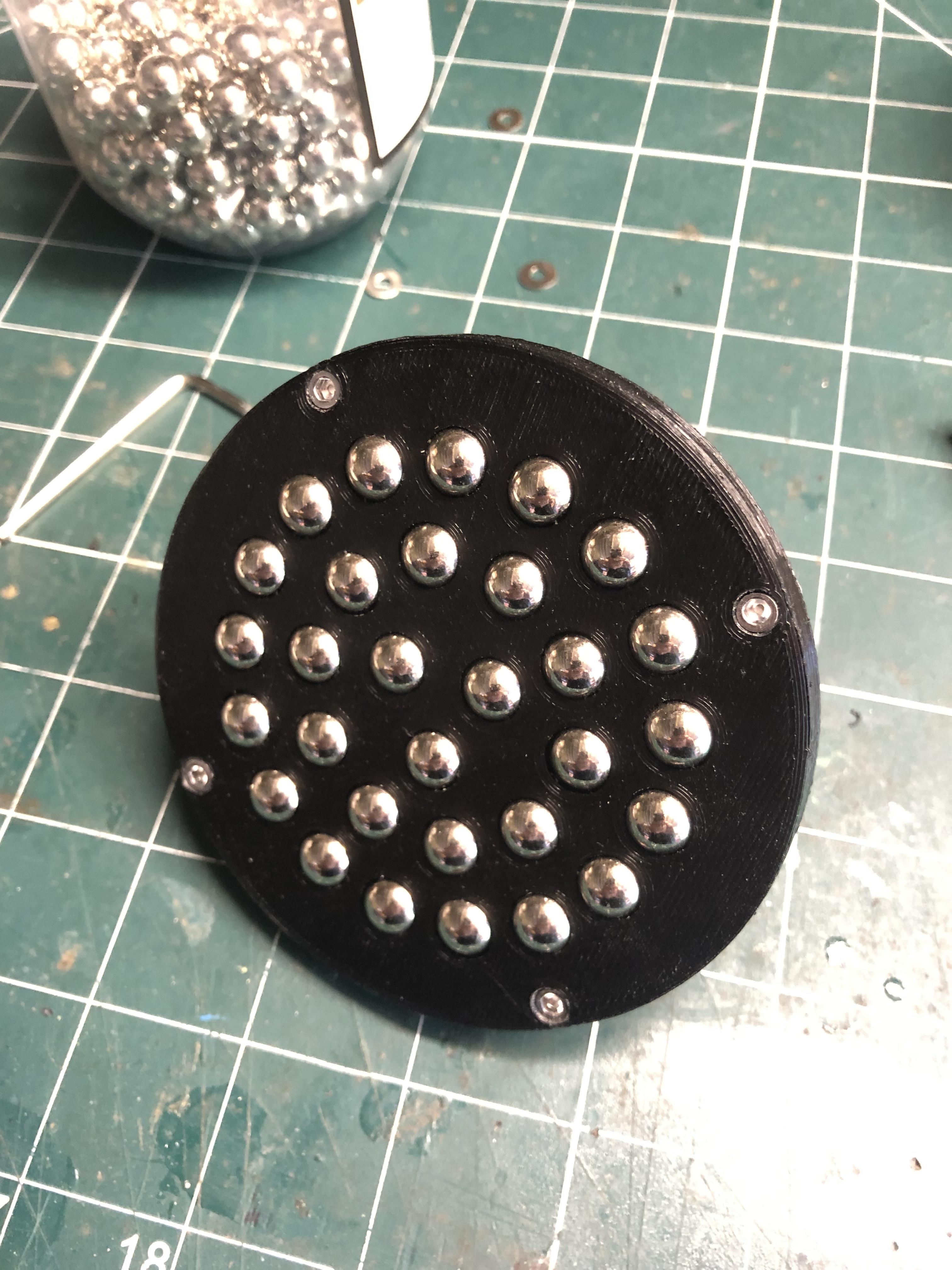
First job is to insert the 3mm Allen head bolts and draw them into the recess's, I have to admit these were a bit tight and too close to the edge of the base, I had to file down the heads on the bolts so they would pull though, I should of made the holes @ 6mm to give plenty of clearance.
With the bolts in place I could move onto assembling the Baren.
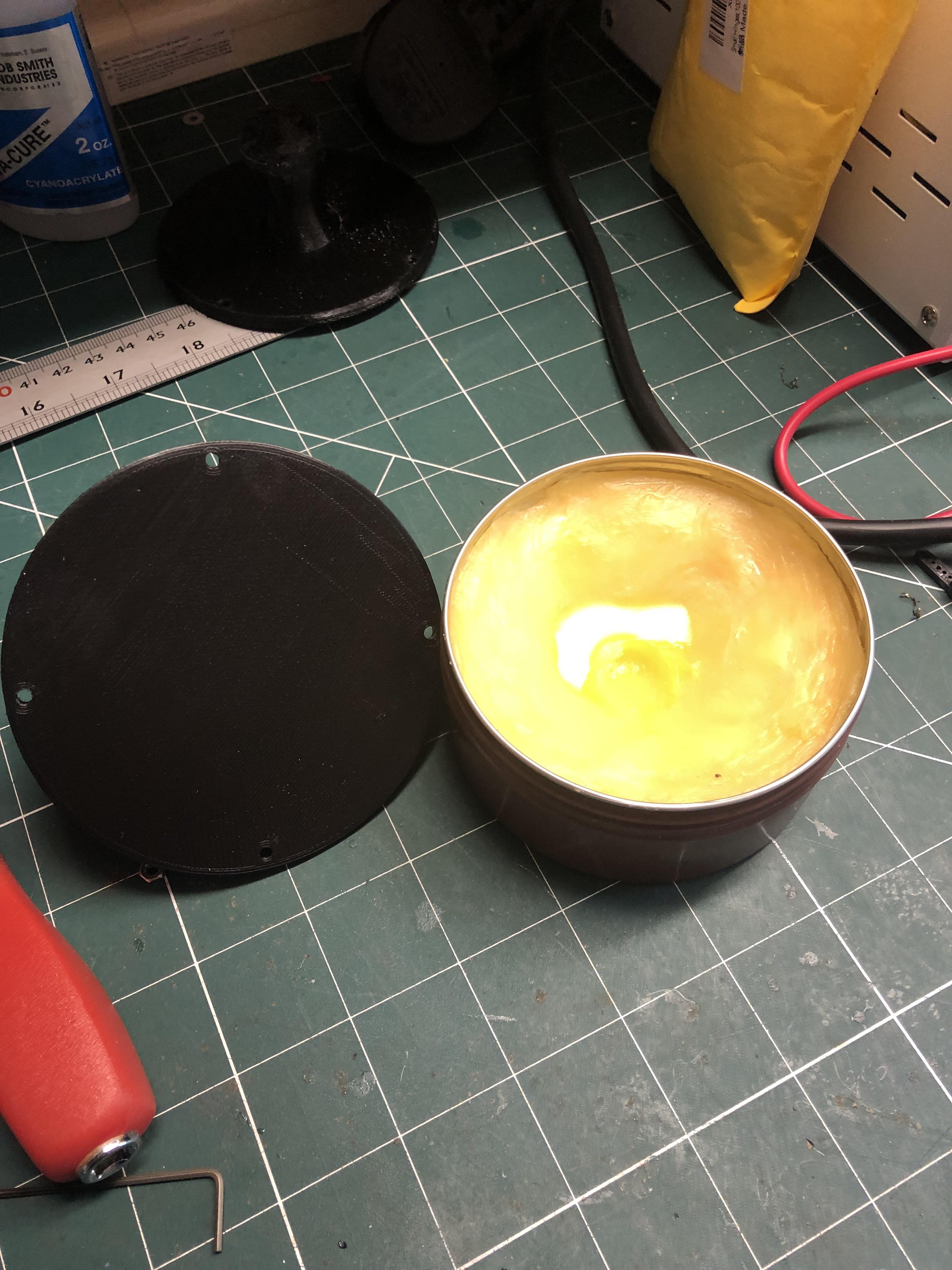
Before inserting the ball bearings, I put a very light coating of beeswax on the underside of the Top plate, I rubbed most of it away with a cloth, it's just to assist with the friction of the ball bearings during the print rubbing process.
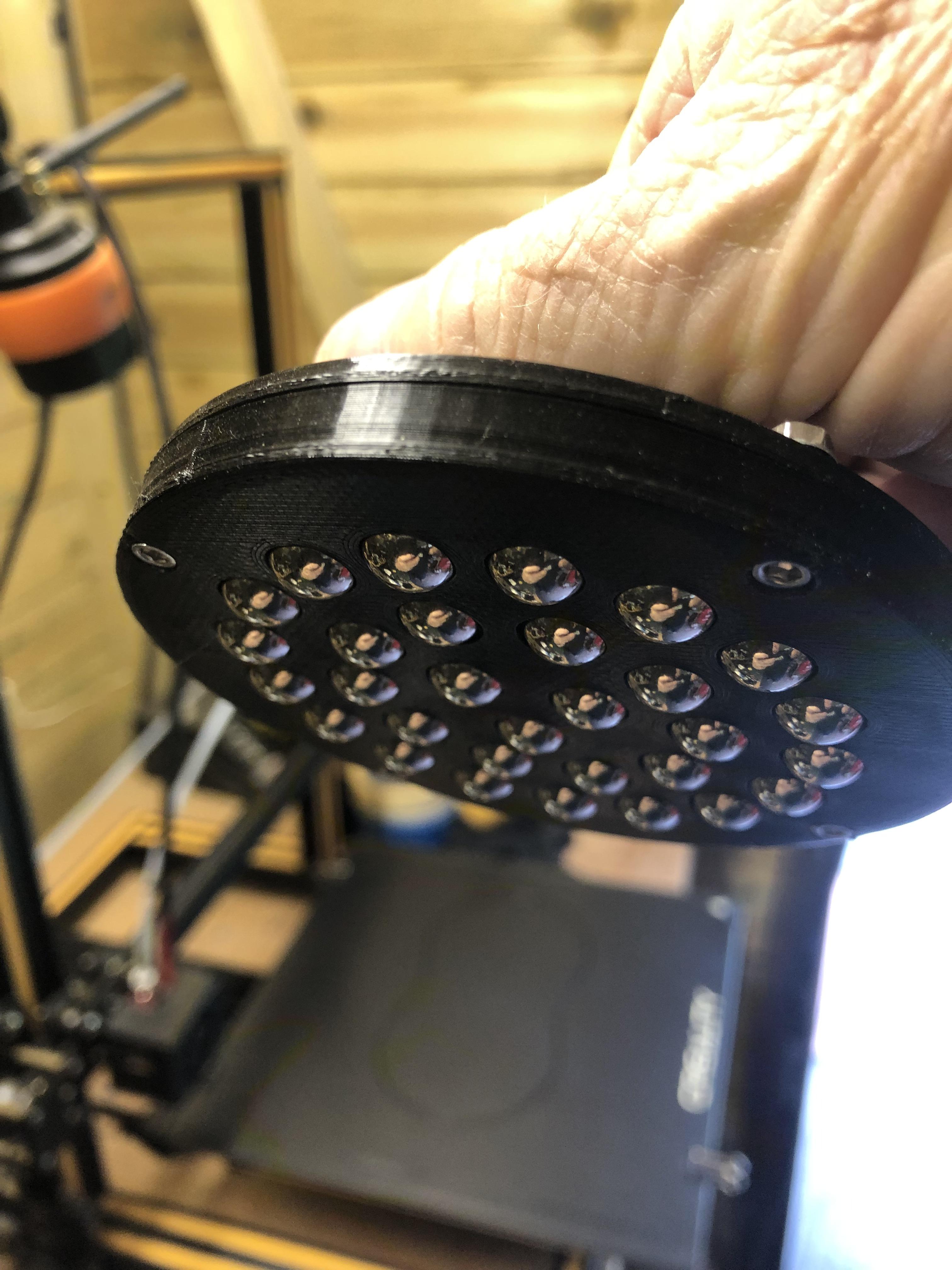
Insert the ball bearings into the holes and secure the top plate with M3 Allen head bolts, try to get bolts which don't protrude through the nut, I fitted washers as well or if they do then file them flush to stop fingers catching the thread etc.
And that's all there is to it, not really, In all honesty it took several attempts with just 3D printing a singular hole, I tried chamfer as well as fillet and decided fillet was the better option.
I only had 9.5mm Ball bearings but the principle would be the same with smaller ball bearings, its getting the fillet size right so when the part is extruded it gives clearance in the holes for the bearings, trial and error really.
PS: We found another use for the Baren, It makes for an excellent back massager too:)
As always I hope you enjoyed this Instructable and I hope it saves someone some money in the process.
Thanks for looking.